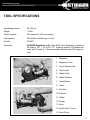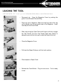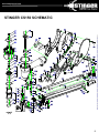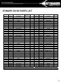
1
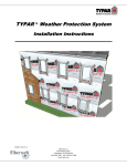
•  Operation
Revised 6/2013
www.stingerworld.com
CS150 CAP STAPLER
OWNER’S MANUAL
!
•  Maintenance
•  Safety
•  Warranty
PLEASE READ!
This manual contains important information about product safety.
www.stingerworld.com
WELCOME TO STINGER
Congratulations on purchasing the STINGER CS150 Cap Stapler. You have selected a brand and
a tool that you can count on to deliver best practice installation, and perform job after job.
Please take the time to read and understand the information contained in this Owner’s Manual
before operating or maintaining the STINGER CS150 Cap Stapler.
The CS150 is intended for securing housewrap, foamboard and roofing felt only.
Improper use of the CS150 could result in serious injury or even death. Most accidents occur
because of the failure to observe basic safety rules and precautions, which are outlined in the
“Important Information” section of this manual.
This Owner’s Manual should be available to anyone who plans to operate the CS150.
1
www.stingerworld.com
TABLE OF CONTENTS
•
Welcome
1
•
Important Information
2
•
Tool Specifications
5
•
Loading the Tool
6
•
Operating the Tool
7
•
STINGER CS150 Schematic
9
•
STINGER CS150 Parts List
10
•
Maintenance and Storage
13
•
Warranty
14
•
Troubleshooting
15
www.stingerworld.com
IMPORTANT INFORMATION
!
PERSONAL SAFETY ITEMS
•
Do not use tool prior to reading the Owner’s Manual.
•
Always wear eye protection that conforms to ANSI requirements (Z87.1) and
provides protection against flying particles both from the front and side. Eye
protection should be worn by the operator and by others in the work area. Eye
protection is required to protect against flying fasteners and debris that could
possibly cause severe eye injury.
•
The employer is responsible to enforce the use of eye protection equipment by the tool
operator and all other personnel in the work area.
•
To prevent accidental injuries:
–  Handle the tool with care
–  Always assume that the tool contains fasteners
–  Always disconnect the air hose from the STINGER CS150 when:
•  loading staples and/or caps
•  performing inspection, maintenance or repair
•  clearing a staple or collated cap jam
•  the tool is not in use
•  leaving the work area
•  moving the STINGER CS150 to another work location
•  handing the STINGER CS150 to another person
•  storing the tool
–  Never point the tool toward yourself or anyone else
–  Never engage in horseplay
–  Never hold or carry the tool with a finger on the trigger
–  Never place a hand or any other part of the body in the fastener discharge area of
the tool while the air supply is connected
2
www.stingerworld.com
IMPORTANT INFORMATION
AIR SUPPLY AND CONNECTIONS
•
Use only clean, regulated compressed air as a power source for this tool. Do not use bottle
gases, combustible gases or oxygen as a power source for the tool as the tool may explode.
•
Do not use air supply pressures that exceed 105 PSI. Exceeding the recommended maximum
operating air pressure will greatly increase tool wear.
•
The air supply must be capable of maintaining the operating air pressure of the tool. Pressure
drops in the air supply can reduce the tool’s driving power.
•
Use a pressure regulator and gauge to allow visual inspection of the air pressure being
delivered to the tool.
•
Use air hoses that have rated pressures of up to 150% of the maximum pressure that can be
generated by the power source. The supply hose should contain fittings that will provide quick
disconnecting from the male plug on the tool.
•
Use quick connect fittings that allow the tool to be unhooked from the air supply quickly and
easily.
•
Do not use fittings that will not allow the tool to exhaust when the air supply is disconnected.
3
www.stingerworld.com
IMPORTANT INFORMATION
OPERATION OF THE TOOL
•
Never inspect, maintain, repair, adjust, clear a jam or store the tool with the air connected.
•
Never use the tool in proximity of flammable gases or liquids, as some tools will create sparks
that can be an ignition source for a fire or explosion.
•
Always inspect the safety device for damage and proper operation prior to operation.
•
Never assume the tool is empty of fasteners.
•
Never point the tool toward yourself or any other persons.
•
Never cycle the tool unless it is in contact with the work-piece.
•
Never use the tool as a hammer or wedging device or drop to the floor from any height.
•
Always remove your finger from the trigger when pausing from cycling.
•
Never tamper with the safety device or use the tool if the safety device is not functioning
properly.
•
Use only 7/8”, 1 ¼” or 1 ½” STINGER StaplePac® cap fasteners with the STINGER CS150
Cap Stapler. Never use any fasteners that are not specified for use in this tool. The CS150
holds 1 coil of plastic caps (200 caps) and 2 strips of staples (100 staples each).
4
www.stingerworld.com
TOOL SPECIFICATIONS
Operating pressure
95-105 psi
Weight
4.2lbs
Staple capacity
200 staples (2-100 count strips)
Cap capacity
200 plastic collated caps (1 reel)
Air inlet
3/8 NPT
Fasteners
STINGER StaplePac® only. Each 2000 count StaplePac consists of
20 strips of 7/8”, 1-1/4” and 1-1/2” 18 gauge staples (100 staples per
strip) and 10 reels of 1” diameter plastic collated caps (200 caps per
reel).
10.
1.  Magazine
2.  Magazine Cover
14.
3.  Cover Release Tab
4.  Cap Feeder
1. / 2.
5.  Staple Track
3.
4.
15.
11.
6.  Staple Follower
7.  Catch Button
8.  Latch
9.  End Cap
12.
10. Exhaust
8.
13.
5.
6.
9.
11. Safety
7.
12. Trigger
13. Nose
14. Quick Clear™ Lever
15. Feed Chute
5
www.stingerworld.com
LOADING THE TOOL
FOR USE WITH 7/8”, 1-1/4”, or 1-1/2” STINGER STAPLEPAC® CAP STAPLES ONLY
•
Disconnect air. Open the Magazine Cover by pushing the
green Cover Release Tab and lifting.
•
Place cap reel in Magazine. Make sure the front end of the cap
coil is placed over the cap guide area of the Magazine. Insert
lead cap into the Feed Chute.
•
Slide caps along the Feed Chute with fingers until they engage
the Cap Feeder. Pull the Cap Feeder back and release to
advance caps until the first cap is under the Nose of the tool.
•
Close the Magazine Cover.
•
Pull back the Staple Follower until the Latch catches.
•
Place staples in Staple Track.
•
Release the Catch Button. Plug into air source. Tool is ready
to use.
6
www.stingerworld.com
OPERATING THE TOOL
1.
Do not use tool prior to reading the STINGER CS150 Owner’s Manual.
2.
Read warning label(s) on the tool.
3.
Visually inspect the tool for worn or damaged parts.
4.
Wear appropriate eye and ear protection.
5.
Install a male pneumatic fitting into the End Cap of the tool, ensuring that the fitting allows the
tool to exhaust any air in the tool when the air hose is disconnected.
6.
Add 2 drops of non-detergent, 20-weight oil into the male fitting daily.
7.
Connect the air hose to the tool using a quick connect fitting, and check the air pressure
reading on the regulator to ensure it does not exceed 105 PSI. Check the tool for any air
leaks.
8.
Place the tool, empty of fasteners, in operating position on a scrap work piece. Fully depress
the Safety and pull the Trigger to verify that the tool cycles.
9.
Disconnect the air hose from the tool when:
•
•
•
•
•
•
•
•
Loading staples and/or caps
Performing inspection, maintenance or repair
Clearing a staple or collated cap jam
The tool is not in use
Leaving the work area
Moving the tool to another work location
Handing the STINGER CS150 to another person
Storing the tool
10.  Following recommended loading instructions, load the fasteners approved for use in the tool.
See Page 6.
7
www.stingerworld.com
OPERATING THE TOOL
11.  Cycle the tool on a scrap work piece to evaluate the depth of penetration by the fastener into
the work piece.
12.  To adjust the depth of penetration, regulate the air pressure at the regulator and/or
disconnect the air hose, adjust the depth control screw, connect the air hose, and cycle the
tool on a scrap work piece to evaluate the adjustment.
13.  Repeat Step 12 as needed to set the correct depth, using the minimum amount of air
pressure to drive the fastener.
8
www.stingerworld.com
STINGER CS150 SCHEMATIC
9
www.stingerworld.com
STINGER CS150 PARTS LIST
Ref.
Number
NNC Part
Number
Description
01
02
03
04
05
06
07
08
09
10
11
12
13
14
15
16
17
18
19
20
21
22
23
24
25
26
27
28
29
30
31
32
33
34
35
36
37
38
39
40
41
42
43
44
45
46
0136665
0135851
0136635
0137973
0135854
0137953
0135856
0137899
0136627
0136628
0136630
0136643
0136642
0137976
0137979
0553031
0136675
0137969
0553029
0136615
0137898
0553001
0136657
0137966
0137897
0136621
0136645
0135897
0136658
0137896
0137895
0135947
0135948
0136623
0136653
0135911
0136640
0136676
0136622
0136620
0136650
0137894
0135907
0137893
0137911
0135910
Screw
Washer
Exhaust Deflector
O-Ring
Washer
Cap Screw(4)
Flat Washer(4)
Cap
Exhaust Seal
O-Ring
Poppet Spring
Poppet O-Ring
Poppet
Piston Stop O-Ring
Cylinder Seal O-Ring
Guide Spacer
Cylinder
Cylinder O-Ring
Cylinder O-Ring
Piston O-Ring
Piston & Driver Assembly
Bumper
Return Seal
Gasket
Body
O-Ring(2)
Barb Fitting(2)
Safety Guide
Spring
Safety
Safety Assembly
Washer
Belt Clip
Trigger Pin
Pin
O-Ring(2)
Bleeder Valve
O-Ring
Spring
Plunger
Trigger Assembly
Tubing
Pin
Cap Feeder
Spring
Feed Cylinder
Parts Kit
*
*
*
*
*
*
*
*
*
*
*
*
*
*
Ref.
Number
NNC Part
Number
Description
47
48
49
50
51
52
53
54
55
56
57
58
59
60
61
62
63
64
65
66
67
68
69
70
71
72
73
74
75
76
77
78
79
80
81
82
83
84
85
86
87
88
89
90
91
92
0135912
0135913
0135914
0135915
0135916
0135917
0137986
0135918
0135925
0137957
0135926
0136608
0135919
0135921
0135922
0135923
0136672
0136631
0136673
0136648
0135892
0135893
0136654
0136624
0136637
0136637
0136652
0136656
0136653
0137892
0136660
0137891
0137890
0137889
0135885
0137888
0137887
0136659
0136651
0136644
0136639
0137886
0136649
0137885
0136611
0135924
Feed Piston
O-Ring
Spring
Piston Stop
Feed Piston Cover
Retaining Ring
O-Ring
Hold Down Spring
Feed Chute
Lock Nut
Screw(2)
Screw(5)
Magazine Right
Magazine Cover
Magazine Left
Screw(2)
Nut
Spring Clip
Negator Spring
Negator Spring Drum
Screw(5)
Static Front Plate
O-Ring
Step Pin
Latch Assembly
Removable Front Plate
Pin
Wear Plate
Pin
Feed Chute Basket
Screw
Magazine Cover
Cover Rod
Magazine
Spring
Button
Housing
Spring
Fixed Spacer
Plug
Spring
Pusher
Spacer
Bracket
Washer
Screw
Parts Kit
*
*
*
*
* Parts included in AS-97384 O-ring and Seal Kit
10
www.stingerworld.com
MAINTANANCE & STORAGE
MAINTENANCE
1.
Disconnect the air hose from the tool when performing inspections, maintenance or repairs.
2.
Use air line lubricators. If lubricators are not available, or if hose length exceeds 10 feet, add
2 drops of non-detergent 20-weight oil daily into the air inlet of the tool.
3.
Whenever repairs or replacement of parts inside the body occur, check the piston “O” ring for
adequate grease lubrication.
4.
Never use any parts other than genuine STINGER replacement parts. To order, call
800-746-5659.
5.
Periodically clean the Magazine and Nose of the tool with a mild solvent.
STORAGE
1.
Disconnect the air hose when storing the tool.
2.
Never store the tool in cold weather environments for any duration of time as any frost or ice
formation in the tool will cause tool failures.
3.
For prolonged storage, add 2 drops of oil to the air inlet of the tool prior to discontinuing use.
Also clean the exterior of the tool with a mild solvent.
13
www.stingerworld.com
WARRANTY
WARRANTY ITEMS
1.
Warranty for cap assemblies, castings and housing castings is one year.
2.
Warranty for bumpers, “O” rings, driver blades and piston rings is not applicable as they are
normal wearing parts whose life is dependent on application.
3.
Warranty for all other parts is 90 days.
WARRANTY CONDITIONS
1.
The beginning date in which the warranty is in force is the date of purchase.
2.
The warranty is not transferable.
3.
The warranty is voided by any of the following:
a.
b.
c.
d.
4.
Abuse, misuse, or damage to the tool
Use of parts other than genuine STINGER parts
Use of fasteners not designated for use in the tool
Modifications to the tool that alter the original function or intent of use of the tool by
anyone other than National Nail
National Nail Corp. retains the right to replace or repair any warranty items it deems
necessary.
14
www.stingerworld.com
TROUBLESHOOTING
Disconnect the air hose from the tool when performing inspections, maintenance or repairs.
PROBLEM:
CORRECTION:
1.
Tool operates, but no fasteners
are driven.
•  Check Magazine for proper fasteners.
Fasteners should slide freely in and out of
the magazine.
2.
Cap leaks air.
•  Tighten cap screws.
3.
Fasteners jam in nose of tool.
•  Remove fasteners from Magazine.
•  Open Quick-Clear™ Lever (if applicable),
remove jammed fastener and close Latch.
•  Load tool.
4.
Weak drive.
•  Check to make sure there is adequate air
supply.
5.
Skipping fasteners.
•  Replace Bumper if worn.
•  Use only recommended fastener sizes.
•  Replace Magazine if worn.
•  Check air supply as it may be too low or too
high.
6.
Fasteners will not drive
completely into work piece.
•  Adjust the depth of drive.
Please contact Inside Sales for technical support if you have any other problems: 800-746-5659
15
Visit our website at
www.nationalnail.com
to learn more about our products
and services.
2964 Clydon SW, Grand Rapids MI 49519, USA
Phone: 800-968-6245 Fax: 616-531-5970
www.stingerworld.com
Contact Inside Sales at
800-746-5659
to place an order for
replacement parts.