1
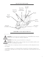
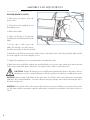
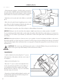
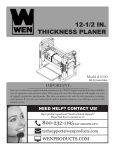
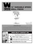
ELECTRIC PLANER
Model # 6530
bit.ly/wenvideo
IMPORTANT:
Your new tool has been engineered and manufactured to WEN’s highest standards for dependability,
ease of operation, and operator safety. When properly cared for, this product will supply you years
of rugged, trouble-free performance. Pay close attention to the rules for safe operation, warnings,
and cautions. If you use your tool properly and for intended purpose, you will enjoy years of safe,
reliable service.
NEED HELP? CONTACT US!
Have product questions? Need technical support?
Please feel free to contact us at:
800-232-1195 (M-F 8AM-5PM CST)
[email protected]
WENPRODUCTS.COM
TABLE OF CONTENTS
2
3
4
5
7
7
10
13
14
16
Technical Data
General Safety Rules
Specific Safety Rules For Planer
Electrical Information
Know Your Planer
Assembly and Adjustments
Operation
Maintenance
Exploded View and Parts List
Warranty
TECHNICAL DATA
Model Number:
Motor:
Speed:
Cutting Width:
Cutting Depth:
Rabbeting Depth:
Weight:
Contents:
2
6530
120 V, 60 Hz, 6A
17,000 RPM
3-1/4˝
1/8˝
11/16˝
6.5 lbs
Planer
Dust Bag
Parallel Fence Bracket
GENERAL SAFETY RULES
Safety is a combination of common sense, staying alert and knowing how your item works. SAVE THESE
SAFETY INSTRUCTIONS.
WARNING: To avoid mistakes and serious injury, do not plug in your tool until the following
steps have been read and understood.
1. READ and become familiar with this entire instruction manual. LEARN the tool’s applications, limitations,
and possible hazards.
2. AVOID DANGEROUS CONDITIONS. Do not use power tools in wet or damp areas or expose them to
rain. Keep work areas well lit.
3. DO NOT use power tools in the presence of flammable liquids or gases.
4. ALWAYS keep your work area clean, uncluttered, and well lit. DO NOT work on floor surfaces that are
slippery with sawdust or wax.
5. KEEP BYSTANDERS AT A SAFE DISTANCE from the work area, especially when the tool is operating.
NEVER allow children or pets near the tool.
6. DO NOT FORCE THE TOOL to do a job for which it was not designed.
7. DRESS FOR SAFETY. Do not wear loose clothing, gloves, neckties, or jewelry (rings, watches, etc.) when
operating the tool. Inappropriate clothing and items can get caught in moving parts and draw you in. ALWAYS
wear non-slip footwear and tie back long hair.
8. WEAR A FACE MASK OR DUST MASK to fight the dust produced by sawing operations.
WARNING: Dust generated from certain materials can be hazardous to your health. Always
operate the tool in a well-ventilated area and provide for proper dust removal. Use dust collection
systems whenever possible.
9. ALWAYS remove the power cord plug from the electrical outlet when making adjustments, changing parts,
cleaning, or working on the tool.
10. KEEP GUARDS IN PLACE AND IN WORKING ORDER.
11. AVOID ACCIDENTAL START-UPS. Make sure the power switch is in the OFF position before plugging
in the power cord.
12. REMOVE ADJUSTMENT TOOLS. Always make sure all adjustment tools are removed from the saw
before turning it on.
13. NEVER LEAVE A RUNNING TOOL UNATTENDED. Turn the power switch to OFF. Do not leave
the tool until it has come to a complete stop.
3
GENERAL SAFETY RULES
14. NEVER STAND ON A TOOL. Serious injury could result if the tool tips or is accidentally hit. DO NOT store
anything above or near the tool.
15. DO NOT OVERREACH. Keep proper footing and balance at all times. Wear oil-resistant rubber-soled footwear. Keep the floor clear of oil, scrap, and other debris.
16. MAINTAIN TOOLS PROPERLY. ALWAYS keep tools clean and in good working order. Follow instructions for lubricating and changing accessories.
17. CHECK FOR DAMAGED PARTS. Check for alignment of moving parts, jamming, breakage, improper
mounting, or any other conditions that may affect the tool’s operation. Any part that is damaged should be properly
repaired or replaced before use.
18. MAKE THE WORKSHOP CHILDPROOF. Use padlocks and master switches and ALWAYS remove starter keys.
19. DO NOT operate the tool if you are under the influence of drugs, alcohol, or medication that may affect your
ability to properly use the tool.
20. USE SAFETY GOGGLES AT ALL TIMES that comply with ANSI Z87.1. Normal safety glasses only have
impact resistant lenses and are not designed for safety. Wear a face or dust mask when working in a dusty environment. Use ear protection such as plugs or muffs during extended periods of operation.
SPECIFIC RULES FOR THE PLANER
WARNING: Do not operate this tool until it is completely assembled and installed according to
the instructions.
1. Wait for the cutter to stop before setting the tool down. An exposed rotating cutter may engage the surface, leading to possible loss of control and serious injury.
2. Hold the power tool by insulated gripping surfaces only in case the cutter contacts its own cord. Cutting a “live”
wire may make exposed metal parts of the tool “live” and could give the operator an electric shock.
3. Secure the workpiece to a stable platform using clamps or another practical method. Holding the work by hand
or against the body leaves it unstable and may lead to a loss of control.
4. Secure the material being planed. Never hold it in your hand or across your legs. Small workpieces must be
adequately secured so that the rotating planer blades don’t pick them up during the forward motion of the planer.
Unstable support causes the blades to bind, resulting in a loss of control and possible injury.
5. Always start the planer before the blade is in contact with the workpiece. Let the blade reach full speed before
using the tool. The planer can vibrate or chatter and possibly kickback if the speed while cutting is too slow.
6. Check the workpiece for nails. If there are nails, either remove them or set them well below intended finished
surface. If the planer blades strike objects like nails it may cause serious personal injury from kickback.
4
SPECIFIC RULES FOR THE PLANER
7. Unplug the planer before changing accessories. Accidental start-ups may occur if the planer is plugged in during
an accessory change. Before plugging the tool back in, check that the trigger lock is OFF.
8. After changing blades, rotate the blade cylinder (cutter drum) to make sure the blades don’t hit any part of the
blade head housing and that the blade locking screws are tight. Loose or misaligned blades have the potential to
strike tool housing and damage the tool as well as cause possible injury.
9. Always hold the tool firmly with both hands for maximum control.
10. Never pull the planer backwards over the workpiece. Loss of control may occur.
11. Do not put fingers or any objects into the chip ejector. Do not clean out chips while the tool is running. Contact
with the blade drum will cause injury.
12. Remove the plug from power source before removing chips. The blades are hidden from view and you may be
cut if the blade is contacted.
13. GFCI and personal protection devices such as electrician’s rubber gloves and footwear will increase personal
safety.
14. Keep handles and hands dry, clean and free from oil and grease. Slippery surfaces cannot safely maintain control of the power tool.
15. Develop a periodic maintenance schedule for your tool. When cleaning a tool be careful not to disassemble any
portion of the tool. Internal wires may be misplaced or pinched and safety guard return springs may be improperly
mounted.
16. Certain cleaning agents such as gasoline, carbon tetrachloride, ammonia, etc. may damage plastic parts.
ELECTRICAL INFORMATION
GROUNDING INSTRUCTIONS
IN THE EVENT OF A MALFUNCTION OR BREAKDOWN, grounding provides the path of least resistance
for an electric current and reduces the risk of electric shock. This tool is equipped with an electric cord that has an
equipment grounding conductor and a grounding plug. The plug MUST be plugged into a matching outlet that is
properly installed and grounded in accordance with ALL local codes and ordinances.
DO NOT MODIFY THE PLUG PROVIDED. If it will not fit the outlet, have the proper outlet installed by a
licensed electrician.
IMPROPER CONNECTION of the equipment grounding conductor can result in electric shock. The conductor with the green insulation (with or without yellow stripes) is the equipment grounding conductor. If repair or
replacement of the electric cord or plug is necessary, DO NOT connect the equipment grounding conductor to a
live terminal.
5
ELECTRICAL INFORMATION
CHECK with a licensed electrician or service personnel if you do not completely understand the grounding
instructions or whether the tool is properly grounded.
CAUTION: In all cases, make certain the outlet in question is properly grounded. If you are not sure, have
a licensed electrician check the outlet.
WARNING: This tool is for indoor use only. Do not expose to rain or use in damp locations.
Guidelines for using extension cords
Make sure your extension cord is in good condition. When using an extension cord, be sure to use one
heavy enough to carry the current your product will draw. An undersized cord will cause a drop in line voltage resulting in loss of power and overheating. The table below shows the correct size to be used according
to cord length and nameplate ampere rating. When in doubt, use a heavier cord. The smaller the gauge
number, the heavier the cord.
AMPERAGE
6A
REQUIRED GAUGE FOR EXTENSION CORDS
25 ft.
50 ft.
100 ft.
150 ft.
18 gauge
16 gauge
14 gauge
12 gauge
Make sure your extension cord is properly wired and in good condition. Always replace a damaged extension cord or have it repaired by a qualified person before using it.
Protect your extension cords from sharp objects, excessive heat and damp/wet areas.
Use a separate electrical circuit for your tools. This circuit must not be less than a #12 wire and should be
protected with a 15 A time-delayed fuse. Before connecting the motor to the power line, make sure the
switch is in the OFF position and the electric current is rated the same as the current stamped on the motor
nameplate. Running at a lower voltage will damage the motor.
WARNING: This tool must be grounded while in use to protect the operator from electric shock.
6
KNOW YOUR PLANER
Dust/Chip
Extraction
Port
Dust/Chip
Extraction
Guide Switch
ON/OFF
Switch
Trigger
Lock
Handle
Depth
Adjustment
Knob
Blade
Wrench
Adjustable
Front Shoe
Drive Belt
Cover
ASSEMBLY AND ADJUSTMENTS
REMOVING OR INSTALLING PLANER BLADES
WARNING: To avoid injury from accidental startups, turn switch OFF and remove the plug
from the power source outlet before making any adjustments.
WARNING: These blades cannot and should not be re-sharpened.
WARNING: The planer blades are sharp and fragile and must be handled carefully to avoid
injury to the user and damage to the blades.
The planer blades have two cutting edges and may be reversed when one of the cutting edges becomes
dull or chipped.
Do not attempt to sharpen or use resharpened blades of any kind. Use only blades designated for use
with this model, as other blades may not clamp securely in blade holder, causing vibration and a decrease
in performance.
7
ASSEMBLY AND ADJUSTMENTS
REMOVING OR INSTALLING
PLANER BLADES (CONT.)
1. Disconnect the planer from the
power source.
2. Using the wrench supplied, loosen
all clamping screws.
3. Slide out the blade.
4. Clean out all chips or foreign matter adhering to the blade drum and the
blade.
5. If one edge is dull, reverse the
blade. If both edges are dull, remove
the blade and replace it with a new blade.
6. Slide the good blade face up into the blade retainer of the blade drum. The ridge along the blade should
be on the opposite side of the clamping screws.
7. Tighten the clamping screws, ensuring that they are tightened evenly.
8. Repeat for the second blade, making sure that both blades are set to the same cutting level and positioned
in the center of the blade drum. Otherwise, your planed surface will be rough and uneven.
CAUTION: Tighten all clamping screws carefully when attaching the blades to the planer. A loose
clamping screw can be extremely dangerous. Check regularly to see that they are tightened securely.
NOTICE: Always change both blades at the same time. Use blades of the same dimensions and weight.
Otherwise, the resulting imbalance can cause vibration and poor planing action while shortening the life of
the blade and the tool.
NOTICE: Your planed surface will end up rough and uneven unless the blades are properly and securely
set. The blades must be mounted so that the cutting edge is absolutely level (parallel to the surface of the rear
shoe).
8
ASSEMBLY AND ADJUSTMENTS
BLADE ALIGNMENT
To ensure an even cut, the blade must be adjusted so that it aligns with the
outside edge of the front and rear shoes. This alignment can be achieved as
follows:
1. Place a straight edge or a piece of wood along the outside surface of the
front and rear shoes. Slide the planer blade to just contact the straight edge
or wood.
2. Make sure the blade sits correctly in the holder groove of the cutter drum.
3. You may then tighten the clamping screws securing the blade and use your planer.
ADJUSTING THE DEPTH OF CUTTING
CAUTION - Always ensure that the tool is switched OFF and unplugged from the power supply before
making adjustments or installing or removing blades. Wait until the blades come to a complete stop before
adjusting the depth of the cut.
1. Disconnect the planer from the power source.
2. Rotate the depth adjustment knob clockwise for a deeper cut or counter-clockwise for a shallower cut.
The minimum cutting increment is 1/128” (0.2 mm).
Note: If it is necessary to accurately determine the depth of cut, plane a
scrap piece of wood, measure the difference in thickness and adjust the
settings accordingly.
CAUTION - Always ensure that the number on the ring is at the “0” position when the tool is not in
use. At this position, the blade cannot cut the workpiece.
SWITCHING ON AND OFF
CAUTION - Before plugging the machine into the power
supply, always check that the trigger switch and trigger lock
work properly.
The tool is equipped with a trigger lock to avoid unintentional start-ups.
To turn the planer on, press the trigger lock and then squeeze the trigger switch. To switch off, release the trigger switch.
9
OPERATION
PLANING
1. Check that the workpiece is held in place securely on
your work surface. Hold the planer firmly with both hands.
Rest the front shoe flat on the workpiece surface, ensuring
that the blades do not make contact with the workpiece.
2. Switch the tool on and wait for the blades to reach full
speed.
3. Move the tool gently forward, applying pressure on the
front of the tool at the beginning of planing, and at the rear
of the tool toward the end of the planing stroke.
4. Push the planer beyond the edge of the workpiece without tilting it downwards.
NOTICE: Planing is easier if you incline the workpiece slightly away from you so that you plane “downhill”.
The rate of planing and the depth of the cut determine the quality of the finish. For rough cutting, you can increase
the depth of cut. To achieve a good finish, you will need to reduce the depth of the cut while advancing the tool
more slowly.
NOTICE: Moving the machine too fast may cause a poor quality of cut and can damage the blades or the motor.
Moving the machine too slowly may burn or mar the cut. The proper feed rate will depend on the type of material
being cut and the depth of the cut. Practice first on a scrap piece of material to gauge the correct feed rate and cutting dimensions.
CAUTION: The motor may stall if improperly used or overloaded. Reduce the pressure (feed rate) or
depth of cut to prevent possible damage to the tool if the motor labors.
CHAMFERING
To make a chamfered cut, first align the “V” grooves
in the front shoe of the planer with the corner edge of
the workpiece.
1. Adjust to desired depth of cut.
2. Place the “V” groove on the front adjustable shoe
over the edge being beveled. Be sure the blades are
not touching the work. Place weight on the depth
adjustment knob so that the “V” groove is absolutely
flat on the edge to be beveled.
3. Grasp the tool firmly with both hands, turn the tool
on and push the plane forward with steady pressure
on the front adjustable shoe.
10
OPERATION
TOOL PARK REST
The park rest swings down to help keep the blade from coming into contact with the work surface when the
planer is not in use. The tool park rest was designed to swing up and out of the way by it itself when the back of
the planer crosses the leading edge of the workpiece.
TOOL PARK REST
PARALLEL FENCE
CAUTION: Always ensure that the tool is switched off and unplugged from the power supply. Wait
until the blades have come to a complete standstill before installing or adjusting the parallel fence.
1. Disconnect the planer from the power source.
2. Use the bracket fixing knob to secure the parallel fence bracket to the left-hand side of the planer.
3. Slide the parallel fence onto the bracket. Position the fence to the desired width.
4. Lock the parallel fence in position with the fence knob and coach bolt.
11
OPERATION
EXTRACTING SHAVINGS
The shavings can be set to flow to either side of the tool to suit
the task at hand.
Set the extraction guide switch to point toward the extraction port
that you wish the chips to flow towards.
If desired, attach the dust bag by simply sliding the nozzle onto
the appropriate dust extraction port.
For efficient operation, empty the dust bag when it is no more
than half full, allowing for better airflow through the bag. Alternatively, the dust extraction adaptor can be fitted to the appropriate
port to allow a dust extraction system or a suitable vacuum cleaner
to be connected to the tool for a cleaner and safer work area.
NOTICE: Shavings may jam in the dust extraction port when cutting damp wood. Never stick your finger into the dust extraction
port. Clean out the shavings with a stick, but only when the cutter
has stopped running and the tool has been unplugged from the
power source.
RABBETING DEPTH GAUGE
CAUTION: Always ensure that the tool is switched off and unplugged from the power supply before
adjusting or installing the rabbeting depth gauge. Wait until the blades have come to a complete stop
before making any adjustments.
1. Disconnect the planer from the power source.
2. Attach the rabbeting depth gauge to the right-hand side of the planer using the depth gauge knob.
3. Loosen the knob, position the depth gauge to the desired rabbeting depth, and then retighten the knob.
When the depth gauge touches the unplaned section of the
workpiece to the right-hand side of the tool, the rabbeting is to
the required depth.
NOTICE: The rabbeting depth gauge allows only approximate
depth setting. If it is necessary to rabbet to a precise depth, plane
a scrap piece of wood, measure the rabbeted depth, and adjust
the setting as necessary.
12
MAINTENANCE
SERVICE: Preventive maintenance performed by unauthorized personnel may result in misplacing of internal
wires and components, possibly causing a serious hazard. We recommend that all tool service be performed by a
WEN Service Center or Authorized WEN Service Station.
TOOL LUBRICATION: Your tool has been properly lubricated and is ready to use. It is recommended that
tools with gears be regreased with a special gear lubricant at every brush change.
CARBON BRUSHES: The brushes in your tool have been engineered for many hours of dependable service.
To maintain peak efficiency of the motor, we recommend examining the brushes every two to six months. Only
genuine WEN replacement brushes designed specifically for your tool should be used.
BEARINGS: Bearings that become noisy (due to heavy load or abrasive material cutting) should be replaced as
soon as possible to avoid overheating or motor failure.
CLEANING: Ventilation openings and switch levers must be kept clean and free of foreign matter. Do not attempt to clean these components by inserting pointed objects through openings.
WARNING: To avoid accidents, always disconnect the tool from the power supply before cleaning or
performing any maintenance. The tool may be cleaned most effectively with compressed dry air. Always
wear safety goggles when cleaning tools with compressed air.
WARNING: Certain cleaning agents and solvents damage plastic parts. Some of these are: gasoline,
carbon tetrachloride, chlorinated cleaning solvents, ammonia and household detergents that contain ammonia.
13
EXPLODED VIEW AND PARTS LIST
14
EXPLODED VIEW AND PARTS LIST
Item #
1
2
3
4
5
6
7
8
9
10
11
12
13
14
15
16
17
18
19
20
21
22
23
24
25
26
27
28
29
30
31
32
33
34
35
Stock #
6530-001
6530-002
6530-003
6530-004
6530-005
6530-006
6530-007
6530-008
6530-009
6530-010
6530-011
6530-012
6530-013
6530-014
6530-015
6530-016
6530-017
6530-018
6530-019
6530-020
6530-021
6530-022
6530-023
6530-024
6530-025
6530-026
6530-027
6530-028
6530-029
6530-030
6530-031
6530-032
6530-033
6530-034
6530-035
Description
Nameplate
Motor cover
Rubber cover
Screw
Right housing
Knob cover
Adjust knob
Regulative shaft
Graduation ring
Ball
Ball
Ball spring
Front shoe
Adjust spring
Adjust support
Belt
Belt cover
Sleeve
Torsional spring
Baffle
Tool carrier
Ball bearing
Blade drum
Ball bearing
Screw
Big washer
Belt pulley
Washer
Nut
Left housing
Air deflector
Driving wheel
Ball bearing
Rotor
Screw
Item #
36
37
38
39
40
41
42
43
44
45
46
47
51
52
53
54
55
56
57
58
59
60
61
62
63
64
65
66
67
68
69
70
Stock #
6530-036
6530-037
6530-038
6530-039
6530-040
6530-041
6530-042
6530-043
6530-044
6530-045
6530-046
6530-047
6530-051
6530-052
6530-053
6530-054
6530-055
6530-056
6530-057
6530-058
6530-059
6530-060
6530-061
6530-062
6530-063
6530-064
6530-065
6530-066
6530-067
6530-068
6530-069
6530-070
Description
Washer
Stator
Carbon brush
Brush lining
Cable clamp
Capacitance
Spring
Knob
Switch
Terminal block
Support
Pin
Rear shoe
Panel strip
Cable bushing
Adjusting plate
Ball spring
Spring seat
Knob
Thumb nut
Fixation frame
Bolt
Baffle
Depth scale
Wrench
Wrench box
Lock-knob
Cable
Connecting hose
Dust bag
Connecting host
Screw
15
LIMITED TWO YEAR WARRANTY
WEN Products is committed to building tools that are dependable for years. Our warranties are consistent with
this commitment and our dedication to quality.
LIMITED WARRANTY OF WEN CONSUMER POWER TOOLS PRODUCTS FOR HOME USE
GREAT LAKES TECHNOLOGIES, LLC (“Seller”) warrants to the original purchaser only, that all WEN consumer power tools will be free from defects in material or workmanship for a period of two (2) years from date of
purchase. Ninety days for all WEN products, if the tool is used for professional use.
SELLER’S SOLE OBLIGATION AND YOUR EXCLUSIVE REMEDY under this Limited Warranty and,
to the extent permitted by law, any warranty or condition implied by law, shall be the repair or replacement of
parts, without charge, which are defective in material or workmanship and which have not been misused, carelessly handled, or misrepaired by persons other than Seller or Authorized Service Center. To make a claim under
this Limited Warranty, you must return the complete power tool product; transportation prepaid, to Great Lakes
Technologies, LLC – 1675 Holmes Road – Elgin, IL. 60123 with a copy of the original receipt which is legible
and clearly defines Date of Purchase including month and year and Place of Purchase.
THIS LIMITED WARRANTY DOES NOT APPLY TO ACCESSORY ITEMS SUCH AS CIRCULAR
SAW BLADES, DRILL BITS, ROUTER BITS, JIGSAW BLADES, SANDING BELTS, GRINDING
WHEELS AND OTHER RELATED ITEMS.
ANY IMPLIED WARRANTIES SHALL BE LIMITED IN DURATION TO TWO (2) YEARS FROM
DATE OF PURCHASE. SOME STATES IN THE U.S., SOME CANADIAN PROVINCES DO NOT ALLOW LIMITATIONS ON HOW LONG AN IMPLIED WARRANTY LASTS, SO THE ABOVE LIMITATION MAY NOT APPLY TO YOU.
IN NO EVENT SHALL SELLER BE LIABLE FOR ANY INCIDENTAL OR CONSEQUENTIAL DAMAGES (INCLUDING BUT NOT LIMITED TO LIABILITY FOR LOSS OF PROFITS) ARISING FROM
THE SALE OR USE OF THIS PRODUCT. SOME STATES IN THE U.S. AND SOME CANADIAN
PROVINCES DO NOT ALLOW THE EXCLUSION OR LIMITATION OF INCIDENTAL OR CONSEQUENTIAL DAMAGES, SO THE ABOVE LIMITATION OR EXCLUSION MAY NOT APPLY TO
YOU.
THIS LIMITED WARRANTY GIVES YOU SPECIFIC LEGAL RIGHTS, AND YOU MAY ALSO HAVE
OTHER RIGHTS WHICH VARY FROM STATE TO STATE IN THE U.S., PROVINCE TO PROVINCE
IN CANADA AND FROM COUNTRY TO COUNTRY.
THIS LIMITED WARRANTY APPLIES ONLY TO PORTABLE ELECTRIC TOOLS, BENCH POWER TOOLS, OUTDOOR POWER EQUIPMENT AND PNEUMATIC TOOLS SOLD WITHIN THE
UNITED STATES OF AMERICA, CANADA AND THE COMMONWEALTH OF PUERTO RICO. FOR
WARRANTY COVERAGE WITHIN OTHER COUNTRIES, CONTACT THE WEN CUSTOMER SUPPORT LINE.
16