1
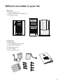
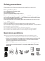
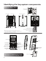
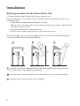
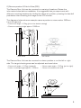
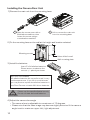
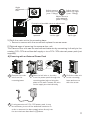
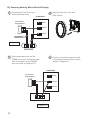
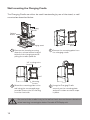
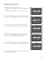
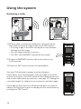
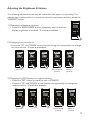
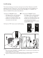
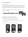
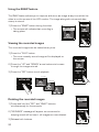
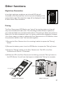
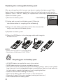
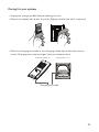
Instruction Manual
VD-8810 Wireless Video Door Intercom
ATTENTION:
Thank you for purchasing the VD-8810 wireless video door intercom.
Before permanently mounting the camera door unit on the wall, please confirm successful
wireless signal transmission by testing the quality of the voice and video image.
Before installation and use, please read this instruction manual thoroughly and keep it safe
for future reference.
1
Miscellaneous
Using the system
Introduction and installation
Index
2
Introduction
Index........................................................................................02
What’s included in your kit............................................ 03
Safety precautions............................................................04
Operation guidelines.........................................................04
Identifying the key system components
Camera Door unit..............................................................06
Portable LCD Display unit..............................................06
LCD Display...........................................................................07
Installation
Selecting a location for the Camera Door unit.....08
Installing the Camera Door unit..................................10
Charging the Indoor Portable LCD Display unit....13
Wall mounting the Charging Cradle..........................14
Setting the Date and Time.............................................15
Using the system
Answering a caller.............................................................16
Adjusting the Brightness & Volume...........................17
Live Browsing......................................................................18
Recording Video Images.................................................19
Changing the number of images recorded............19
Using the SNAP feature.................................................20
Viewing the recorded images......................................20
Deleting the recorded images.....................................20
Other functions
Night-time illumination.....................................................21
Pairing.....................................................................................21
Replacing the rechargeable battery pack..............22
Caring for your system...................................................23
Troubleshooting................................................................. 24
IQ America Two Year Warranty..................................26
What’s included in your kit
Main units
1 x Camera Door Unit
1 x Indoor Portable LCD Display Unit
1 x Charging Cradle
Accessories
1 x AC Adaptor
1 x Rechargeable Battery pack
6 x AA Alkaline Batteries
4 x Mounting Screws
4 x Screw Pegs
1 x Instruction Manual
3
Safety precautions
Please observe the following precautions when installing or using the kit.
Rechargeable Battery Pack
Do not disassemble the battery pack.
Do not dispose of in fire.
Use only the specified battery pack in the kit.
Do not use this battery pack in other equipment.
Only charge the battery pack using the charging cradle & AC adaptor supplied.
Do not bring the battery terminals (+/-) into contact with a metal surface/object.
Do not hold the battery pack by the wires.
Should any liquid leak from the battery pack, avoid contact with your skin or eyes.
Indoor LCD Display Unit
Ensure the AC adaptor is securely plugged into the main power outlet.
Do not use within 22cm of a person wearing a cardiac pacemaker - the operation of
the pacemaker could be affected.
Do not install/use in damp, steamy or dusty environments.
Do not hold the LCD monitor to your ear - your hearing could be damaged.
Do not install in an unstable location or where subject to strong vibration.
Operation guidelines
Avoid using the Indoor Portable LCD Display Unit in the following areas
• Close to a fire, thermal appliance or other source of extreme heat/cold.
• Within 3m of a television, microwave oven, personal computer, wireless LAN
equipment, wireless audio/visual equipment - the radio frequency waves
emitted by these devices can affect operation.
• In direct sunlight.
• Where extreme fluctuations in temperature can occur - if moving the unit
from a warm to cold environment, or vice versa, please allow 30 minutes
before use.
4
The following can also affect successful operation of the system
• Metal doors and shutters.
• Walls with aluminium foil insulation.
• Concrete or galvanized metal walls.
The effective communication range is 100m in free air space (line of sight). This
range will be significantly reduced by the number and thickness of walls through
which the signal is required to pass - please keep to a minimum wherever possible.
About the radio frequency transmitter
• This unit transmits a wireless signal in the frequency range 2.4
- 2.4835GHz.
• The modulation system is GFSK and the interference-causing
radius is 80m.
This unit shares a frequency band with a wide range of equipment: i.e. industrial,
scientific and medical equipment, licensed and unlicensed low-power radio
transmitters such as those used for RFID applications in factories/warehouses
and amateur radio stations. Before use please confirm that no such equipment is in
use in your vicinity.
In the event that this unit causes unwanted interference to such device, please
discontinue use immediately and contact the customer service center for
consultation on interference avoidance measures.
Privacy & portrait/image rights
• Please respect the privacy and image rights of others when using this
equipment. By using this equipment the user assumes total responsibility in
upholding these rights.
• Images stored must not be used for any purpose other than that for which the
equipment is designed.
• Images should be deleted once no longer required - see page 19 for details of
how to delete the stored images.
5
Identifying the key system components
Camera Door Unit
Removal of wall
mounting plate
Microphone
Wall mounting plate
Camera lens
Push button Indication light
Speaker
Battery compartment
Terminals for external 16V supply
Note:
- Visitor image will be impaired if the ambient backlight is very strong.
- The video image is displayed in color during daytime or in well-lit area, but it is
displayed in black and white at night or in dark area.
Camera unit adjustment
Pairing button
LCD display
Speaker
“Talk” button
Accept incoming call
“Snap” button
Record camera view
“Browse” button
Instant view of camera
“Scroll” buttons
Select menu items
Adjust volume
“Off” button
End conversation
Power off
“Play” button
Playback recorded images
“Brightness” button
Adjust LCD image
brightness
Microphone
Portable LCD Display Unit
6
Rechargeable
battery pack
Battery cover
LCD Display
1
3
2
4
1
RF transmission condition
2
Excellent
Battery power condition indicator
(Portable Indoor Display Unit)
Excellent
• Battery status after 6 hours full charging.
• Operation temperature at 20 deg. C
• Continuous talking: 2 hours
• Standby: 120 hours
Good
Weak
Good
None
Low
• Please charge the battery.
Flat
3
Low battery indicator
(Camera door unit)
4
Date and time indications
The date and time is displayed at the
bottom of the screen.
(For date and time setting
• When the camera batteries are
running low, the icon will blink at the
upper right corner of the screen
for 10 seconds during talking or live
browsing.
• Based on average 3 x 10 second
activations per day, the estimated
battery life is approx. 5 months.
See page 15)
7
Installation
Selecting a location for the Camera Door Unit
1) Areas to avoid when mounting the door camera unit
The performance of the system may be affected when mounting the unit in the
following areas • Areas that are subjected to vibration or shock.
• Near a source of hydrosulphuric, phosphorus, ammonia, sulphur, carbon, acid,
dust and noxious fumes.
• An enclosed area that may cause echo
• Where rain or water may directly hit the back of the unit.
The video image may be seriously impaired where the camera faces directly into
the sun, and also in the following situations.
1
2
SKY
3
WHITE
WALL
1 Location where the background is primarily occupied by the sky, such as in
the upper floor of an apartment building.
2 Location which has an adjacent white wall that will directly reflect sunlight.
3 Location that receives direct bright sunlight.
8
2) Camera position & Field of View (FOV)
The Camera Door Unit can be mounted in a variety of locations. Review the
information below before installation. It is suggested that you experiment with
different mounting locations by holding the camera in position, pressing the doorbell
pushbutton then checking the image on the LCD monitor.
The diagrams below show an example camera position to view a visitor 500mm
from the camera.
46 Deg.
SHOOTING AREA
420mm
• Camera tilt angle = 0 Deg. (this is the default setting).
• Camera mounting height approx. 1500mm
560mm
1290mm
1500mm
1710mm
500mm
SHOOTING AREA
500mm
59 Deg.
TOP VIEW
SIDE VIEW
The Camera Door Unit can be mounted in a lower position or on the left or right
side. The target shooting area can be adjusted as shown below.
• Camera pan angle = 15 Deg. (to the right).
• Camera mounted to left side
SIDE VIEW
1030mm
1100mm
500mm
620mm
500mm
46 Deg.
1710mm
420mm
• Camera tilt angle = 15 Deg. (upward).
• Lower mounting height approx. 1100mm
59 D
eg.
TOP VIEW
9
Installing the Camera Door Unit
1) Remove the main unit from the mounting base
1
Open the screw cover with a
flat blade screwdriver, then
loosen the screw using a
crosshead screwdriver.
2
Lift to remove the main unit
from the mounting base.
83.50mm
2) Fix the mounting base on the wall at the height and location selected
Mounting screws
Holes drilled in wall.
Wall mounting plate.
3) Install the batteries
Insert 6 x AA alkaline batteries.
Please ensure to observe the
correct +/- polarity as shown.
BATTERY STATEMENT
AA alkaline batteries do not perform well in very
cold temperatures. If you live in a cold climate
you may want to replace the alkaline batteries in
the Door Camera unit with AA Lithium batteries.
CAUTION
Please use the specified batteries only.
Do not mix new and used batteries
4) Adjust the camera lens angle
• The camera lens is adjustable to a maximum of 15 degrees.
• Please note that the video image may become slightly distorted if the camera
angle is set to maximum upper left/right adjustment.
10
Angle
adjustment
lever
Adjust camera
view to the left
(max. 15deg.)
Adjust camera
view to the right
(max. 15deg.)
Adjust camera
view upwards
(Max. 15deg.)
Examples of possible camera adjustment
Camera looks
upwards
Camera looks
to the right
Camera looks
up & right
5) Re-fit the main unit to the mounting base
• Ensure to secure with the screw and replace the screw cover.
6) Optional ways of powering the camera door unit
The Camera Door unit can be used without batteries by connecting it directly to the
existing 12V−16V wired doorbell supply or to a 12V−16V external power pack (not
supplied).
A) Powering with an External Power Pack
Power
Powersupply
supply
Power
wires
wires
supply wires
2
1
Remove the main
unit from the
mounting base.
4
If using an external 12V−16V power pack, it may
be necessary to cut off the attached connector in
order to connect the bare supply wires directly into
the terminals as described in (2) above.
Pass the bell wire or the wire
from the power pack through the
mounting plate before fixing the
plate to the wall. Connect the wire
to the supply terminals directly.
3
Re-fit the main unit
to the mounting
base and secure
with the screw.
11
B) Powering Existing Wired Doorbell Supply
1
Remove the Front Push and
disconnect the wires.
2
Remove the cover from the
Door Chime.
4
Finally, connect the wires from the
front push to Camera Door Unit as
shown in Diagram 2.
CHIME BASE
Transformer
Supply Output
REAR
16V
TRANS
FRONT
DISCONNECT
FRONT PUSH
Diagram 1
FRONT PUSH
3
Disconnect the wire from the
FRONT terminal in the chime base
and re-connect it to the TRANS
terminal (refer to Diagram 2).
CHIME BASE
Transformer
Supply Output
REAR
16V
TRANS
FRONT
CAMERA DOOR UNIT
Diagram 2
12
Charging the Indoor Portable LCD Display unit.
The indoor portable LCD display unit will need to be charged for approximately 6 - 8
hours before first use.
1) Install the battery pack
1
Remove
the battery
compartment
cover.
2
Connect the battery connector to
the socket located in the battery
compartment. Seat the battery
pack into the compartment.
3
Re-fit the battery
cover - do not
remove the foam
cushion.
2) Assemble the charging cradle
• Insert the plug from the AC adaptor into the
socket on the base of the charging cradle. Secure
the cable under the cord grip.
• Fit the charging cradle onto the stand and snap
into place.
3) Plug the AC adaptor into a 120VAC outlet
Charging
indicator light
4) Place the Indoor Portable LCD Display unit
into the charging cradle
• A full charge will take around 6 hours,
longer if the unit is used during charging.
• The charging indicator light will extinguish
when charging is complete.
• It’s ok to leave the LCD unit in the charging
cradle - it cannot be over-charged.
• Ensure the charging terminals are kept
free from dust and dirt.
• If the system is not being used for a period
of time, remove the battery pack.
13
Wall mounting the Charging Cradle
The Charging Cradle can either be used free-standing by use of the stand, or wall
mounted as described below.
Charging
Cradle
Release
button
Mounting
plate
Charging stand
1
Remove the stand by pressing
down the release button located
behind of the charging stand &
pulling the cradle upwards.
2
Remove the mounting plate from
the charging cradle.
4
Hang the Charging Cradle
securely on the mounting plate
and push it down so that it snaps
in place.
“UP” marking to the
front side.
Mounting
screws
3
Mount the mounting plate to the
wall using the screws and pegs
provided. Ensure the UP marking
is on the front side.
Be sure to fix the cradle firmly to the wall so that it does not become detached
when inserting/removing the Indoor Portable LCD Display unit.
14
Setting the Date and Time
1) Hold the “PLAY” button for 3 seconds.
The date and time will appear with the YEAR highlighted as
shown.
Press the “UP” and “DOWN” arrows to select the year.
2) Press the “PLAY” button to move to the MONTH selection.
Press the “UP” and “DOWN” arrows to select the month.
3) Press the “PLAY” button to move to the DATE selection.
Press the “UP” and “DOWN” arrows to select the date.
4) Press the “PLAY” button to move to the HOUR selection.
Press the “UP” and “DOWN” arrows to select the hour.
Ensure the correct AM/PM setting is selected.
5) Press the “PLAY” button to move to the MINUTE selection.
Press the “UP” and “DOWN” arrows to select the minute.
6) Press the “OFF” button to complete the settings and exit
Date & Time Setting mode.
15
Using the system
Answering a caller
1) When a visitor presses the pushbutton, ring tones can be
heard and the camera image shows on the LCD monitor.
• A moving image of the visitor will appear for ten seconds
followed by a still image.
• The still image is stored in memory.
• The “OFF” and “ANSWER” buttons will blink slowly.
OFF Key
ANSWER
Key
2) Press the “ANSWER” button to talk to the visitor for up
to 60 seconds.
3) Press the “OFF” button to finish the conversation.
You have 150 seconds to answer a call and initiate a
conversation. If you do not answer a call, an image of the visitor
is stored in memory. The PLAY button will blink slowly to alert you
that a visitor called while you were out - see page 19 “Viewing the
recorded images” for details of how to view the recorded image.
Conversations are limited to a 60 second duration to conserve
battery life should you forget to manually end the conversation by
pressing the “OFF” button.
16
Adjusting the Brightness & Volume
The following adjustments can only be made while the system is operating. The
easiest way to achieve this is to press the doorbell pushbutton and then press the
“ANSWER” button.
1) Changing the Display brightness
• Press the “BRIGHTNESS” button repeatedly until the desired
display brightness is achieved - 5 levels are available.
2) Changing the voice volume
• Press the “UP” and “DOWN” arrow buttons during the conversation to change
the voice volume - 5 levels are available.
Sound off
Default setting
(Level 4)
Maximum
(Level 5)
3) Changing the LCD Display unit ringtone volume
• Press the “OFF” button to place the unit in STANDBY
• Press the “UP” and “DOWN” arrow buttons during standby to change the
ringtone volume - 5 levels are available.
Sound off
Default setting
(Level 4)
Maximum
(Level 5)
17
Live Browsing
This function allows you to monitor the view from the Door Camera on the LCD
display at any time. Please note - the Live Browsing feature is only available if the
Door Camera Unit is powered via mains power (see page 11 for details). The
feature is disabled when powered by batteries.
1) Press the “BROWSE” button.
OR 2) Press the “ANSWER” button.
• The Camera Door unit is activated.
• The Camera Door unit is activated.
• The LCD monitor will display the
• The LCD monitor will display the
image from the Camera Door unit.
image from the Camera Door unit.
• Sound from the Camera Door unit
• Sound from the Camera Door unit
microphone can be heard.
microphone can be heard.
• You can talk to the person outside
via the LCD monitor.
3) Press the “OFF” button to exit Live Browsing.
Notes:
• After pressing the “BROWSE” or “ANSWER” button, it may take up to 4 seconds for the
‘Live Browsing’ feature to activate.
• Conversations are limited to a 60 second duration to conserve battery life should you
forget to manually end the conversation by pressing the “OFF” button.
18
Recording Video Images
Automatic Recording
Video images are automatically recorded each time a visitor presses the doorbell
pushbutton. Each image has a date and time stamp that indicate when the visit
occurred. The system can store a maximum of 163 images; when this limit is
reached, the oldest image will be automatically deleted to allow a new image to be
stored.
By default, the number of images stored per visit is set to TWO; this can be
changed as described below.
1st image
Call
Answered
1 sec
2
1
1 sec
Still image 1 - captured 1 sec. after call
2nd image
Still image 2 - captured 2 secs. after call
Changing the number of images recorded
1) Press and hold the “SNAP” button for two seconds.
• The options for number of recorded images will appear.
2) P
ress the “UP” and “DOWN” arrow buttons to select the required number of
images (1, 2 or 3).
3) Press the “OFF” button to complete the settings and exit.
Default setting
(2 images)
19
Using the SNAP feature
The SNAP feature allows you to capture and store an image at any time whilst live
video is on the screen of the LCD monitor. The image along with a time and date
stamp is stored.
1) Press the “SNAP” button during live video.
• The screen will indicate that recording is
taking place.
Viewing the recorded images
The recorded images can be viewed at any time.
1) Press the “PLAY” button.
• The most recently stored image will be displayed on
the screen.
2) P
ress the “UP” and “DOWN” arrow buttons to browse
through the images stored.
3) Press the “OFF” button to exit playback.
1st Image
2nd Image
3rd Image
Deleting the recorded images
1) Press and hold the “OFF” and “SNAP” buttons
simultaneously for five seconds.
2) “NO IMAGE” message will appear on screen and a
beeping sound will be heard - all images are now deleted.
3) Release both buttons.
20
NO IMAGE
Other functions
Night-time Illumination
In low light night-time conditions, an infra-red LED light will
illuminate on the Camera Door unit to improve the quality of the
transmitted image. Note that the image will be displayed in black
& white under these conditions.
Pairing
The Door Camera and LCD Monitor are “paired” by a coding system so they will
only communicate with each other. This encoding provides a secure system so
your video and audio are not shared with others. This pairing is taken care of at the
factory for the units contained in your kit, hence no actions are necessary. However,
if for some reason you have to replace the Door Camera unit or LCD Monitor, follow
the procedure below to “pair” the new units together.
1) Remove the Door Camera from it’s mounting bracket to expose the “Pairing”
button.
2) Remove the battery cover from the LCD Monitor to expose the “Pairing” button.
3) Press the “Pairing” button on the Door Camera unit. The LED in the Door
Pushbutton will blink for 30 seconds.
4) Whilst the LED in the Door Camera unit is blinking, press the “Pairing” button in
the LCD Monitor. You will hear five beeps to indicate that “Pairing” is complete.
Pairing
Button
Pairing Button
Portable indoor display unit
Outdoor camera unit
21
Replacing the rechargeable battery pack
After a prolonged period of use you may have to replace the battery pack. If the
battery does not recharge completely or does not hold a charge you will need to
replace it. Use a “THB-121” battery for replacement. Follow the procedure below to
replace the battery pack.
1) Remove the battery cover.
Low battery
2) Unplug and remove the old battery pack. (Follow the
instructions below for recycling of the old battery).
3) Plug in the new battery pack and position the wires so that
they do not obstruct the battery cover.
4) Replace the battery cover.
5) Place the LCD Monitor in the charging cradle and charge for
at least 6 hours.
NOTES:
• Please use the “THB-121” (sold separately).
• Specification: Ni-MH battery 3.6V 750Ah.
Ni-MH Recycling your old battery pack
• An Ni-MH battery is supplied for use in this product.
•Ni-MH batteries are a precious recyclable resource.
• At the end of it’s life, please tape up the used battery pack or place it into a plastic
bag, then put it into a rechargeable battery recycling box. See your local authority
for information regards the location of such recycling facilities.
• Observe caution when handling the battery.
• Don’t let the battery pack short-circuit - it can cause a fire.
• Please don’t peel off the outer package (coating and tube etc.).
• Don’t disassemble the battery pack.
22
Caring for your system
• Unplug the charging cradle before cleaning the unit.
• Wipe the surfaces with a soft, dry cloth. Slightly moisten the cloth if required.
• Wipe the charging terminals in the charging cradle with a soft cloth once a
month. Charging time may be longer if the terminals are dirty.
Portable indoor display unit
Charging cradle (Top view)
Charging terminals
23
Troubleshooting
Symptoms
Probable causes & solutions
Subjects show up in black and white
or background shows up in greenish.
Is the background dark, such as at night time?
• Subjects shows up as black and white due to
color-dulling when it becomes dark. Also could
appear “greenish” in areas covered by outdoor
lights. This is normal at night when lighting is
provided by the IR LED in the Door Camera unit.
The visitors face is dark in the video
image.
If the Door Camera unit is mounted in an area
with a bright backlight (either from sunlight or
outdoor lighting) the visitor’s face may be in
silhouette.
• Adjust the LCD brightness level
• Re-locate the camera to a position with no
backlight.
• Check that the camera lens is not dirty.
The video image shows up unclearly
or is out of focus.
• Check the lens for condensation
The whole video image shows up
whitish or blackish.
• Check that the brightness setting is correctly
adjusted. The video image shows up whitish or
white lines or rings show up.
It may be difficult to see the image if the camera
lens receives strong light such as sunlight.
• Re-locate the camera to a position with no
direct sunlight.
There are small black spots in the
background of the image.
Does the sun show up in the image? The center
of the sun can appear as black spots if the sun is
in view.
The video image flickers.
Fluorescent lights nearby to the Camera Door
unit can cause the image to flicker.
The video image is distorted. The
voice is cut off.
Is a microwave oven or a wireless LAN device in
operation near to the LCD Monitor unit?
• Re-locate the LCD Monitor away from such
equipment.
The display is completely black.
Is the unit in standby?
• Press any button to energise the display.
Has the battery run out of power?
• Please charge the battery.
24
Troubleshooting
Symptoms
Probable causes & solutions
A howling noise distorts the sound.
If the LCD Monitor is too close to the Door
Camera unit, a howling sound can occur.
• Re-locate the LCD Monitor further away from
the Door Camera unit.
The ring tone cannot be heard.
Has the battery run out of power?
• Please charge the battery.
The charging lamp does not illuminate
when the LCD Monitor unit is placed
in the charging cradle.
Is the AC adaptor disconnected from the socket
or the charging cradle?
• Please check all power connections.
Is the LCD Monitor unit placed in the charging
cradle correctly?
• Remove then replace the LCD Monitor unit
The OFF button should blink when correctly
inserted.
Are the charging terminals dirty?
• Clean the charging terminals with a dry cloth.
Is the battery pack new or has the battery
become completely exhausted?
• Leave the unit on charge - normal charging
should resume after a short while.
is displayed after a short period
of use even if the battery is charged.
The battery pack requires replacement.
• Please purchase and install a new battery pack.
The system does not work in spite of
handling/installing correctly.
The behavior of the unit is strange.
Please try the following methods.
• Manually “Pair” the Camera Door unit and LCD
Monitor unit (see page 20).
• Remove then re-insert the battery pack(s).
If normal operation cannot be achieved, please
call Technical Consultation at 1-800-296-1869.
Technical Assistance
If you require technical assistance with regards the installation,
operation or use of this product, please call
Technical Consultation
on
1-800-296-1869
25
IQ America Two Year Warranty
This is a “Limited Warranty” which gives you specific legal rights. You may also have
other rights which vary from state to state and province to province.
For a period of two years from the date of purchase, any malfunction caused by
factory defective parts or workmanship will be corrected at no charge to you. To
obtain a refund or a replacement, return the product to the place of purchase.
NOT COVERED: Repair service, adjustment and calibration due to misuse, abuse or
negligence. Unauthorized service or modification of the product or of any furnished
component will void this warranty. This warranty does not include reimbursement
for inconvenience, installation, setup time, loss of use or unauthorized service.
This warranty covers only IQ America products and is not extended to other
equipment and components that a customer uses in conjunction with our products.
This warranty is expressly in lieu of all other warranties, express or implied,
including any warranty, representation or condition of merchant ability of that
the products are fit for any particular purpose or use, and specifically in lieu of all
special, indirect or incidental or consequential damages.
Repair or replacement shall be the sole remedy of the customer and there shall
be no liability on the part of IQ America for any special, indirect, incidental or
consequential damages, including but not limited to any loss of business or profit,
whether or not foreseeable. Some states or provinces do not allow the exclusion
or limitation of incidental or consequential damages, so the above limitation or
exclusion may not apply to you. Retain receipt for warranty claims.
The changes or modifications not expressly approved by the party
responsible for compliance could void the user’s authority to operate
the equipment.
To comply with the FCC RF exposure compliance requirements,
this device and its antenna must not be co-located or operating to
conjunction with any other antenna or transmitter.
This equipment should be installed and operated with minimum
distance 20cm between the radiator & your body.
26