1
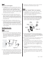
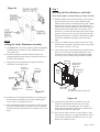
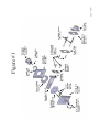
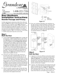
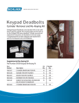
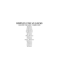
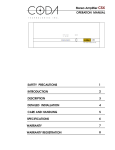
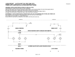
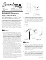
Face
For
Assistance
Call:
1-800-522-7336
Edge
of
Door
of Do
or
Temp
late
Centerline
8 am - 5 pm, Monday - Friday, MST
Door Hardware
Installation Instructions
Single Cylinder Deadbolt
NOTE: Deadbolts fit doors 1-3/4” to 2-1/4” thick.
For thicker doors, please call customer service.
Carefully unpackage all components and place them within easy
reach. Find Figure #1 on Page 5 of these instructions for a listing
and drawing of each component. Detach Figure #1 and place
beside the components for easy reference. Check your door to
see if it has been prepped (pre-drilled) for installing a deadbolt.
If your door has been prepped for installation, start at Step 4. If
your door has not been prepped for installation, you will need a
#2 Phillips screwdriver, a drill, a 2-1/8″ hole saw, a drill, a 7/64″
drill bit, a 1″ drill bit, a chisel, a pencil, tape and an awl (or nail).
Figure #2
(A)
B) The backset is the distace from the edge of the door to the
center of the cross bore hole. Standard backsets are 2-3/8″
and 2-3/4″. Determine the backset of the deadbolt latch (Part
#1) by checking the marking on the latch itself. If the latch
is not marked, measure the latch between points A and B
to determine the backset, as shown in Figure #2. Once you
know your backset, find the point on the template where
the centerline crosses the vertical line that corresponds with
the correct backset. Using the awl (or nail) mark this point,
making sure that it is marked well enough to see on the door
once the template is removed.
C) Follow the centerline around the edge of the door and using
a pencil, extend the centerline onto the edge of the door. The
mark should be parallel to the floor. Once this mark is made,
you may remove the template from the door.
(B)
D) Measure the thickness of the door. Doors vary in thickness
depending on the manufacturer. Determine the distance to
the center of the edge of the door (half the thickness of the
door). Using the awl (or nail), mark a point on the edge of the
door where the centerline pencil mark (from Step 1C) and the
center of the edge of the door meet (half the thickness). See
Figure #3.
For 2-3/8″ Backset
3-1/2″
2-3/8″
Cross Bore
Hole - 2-1/8″
Diameter
Step 1
Mark the Door
A) Locate the Door Preparation Template which is included
with these instructions. Fold the template along the “edgeof-door” line. Important: Before positioning the template,
make sure that you are aligning it on the non-hinged edge of
the door. Carefully position the template so that the narrow
portion of the template wraps around the edge of the door,
and the large portion of the template remains on the face
of the door, see Figure #2. Slide the template up or down
on your door so that the horizontal centerline is located at
a height that is attractive in appearance and at least 5-1/2″
above the center of the doorknob hole. Once you have chosen
the height, tape the template to the door.
Latch
Backset
Measurement
2-3/8” or 2-3/4”
Edge Bore
Hole - 1″
Diameter
Mark from
Step 1B
Mark from
Step 1D
Centerline
Minimum
5-1/2″ to center
line of doorknob cross
bore hole
2-3/4″
3-3/4″
For 2-3/4″ Backset
Step 2
Drill the Door
Mark from
Step 1C
Door Thickness
Faceplate
Mortise
Area
Figure #3
A) Using the 2-1/8″ hole saw, drill the cross bore hole centered
on the mark made on the face of the door from Step 1B. See
Figure #3. Important: To avoid splintering or marring the
door, drill from one side of the door until the pilot bit comes
through the door. Then drill from the other side of the door,
using the hole made by the pilot bit as your guide until the
cross bore hole is complete.
B) Using the 1” bit, drill the edge bore hole centered on the mark
made on the edge of the door where the centerline and center
thickness met from Step 1D, see Figure #3. Important:
Make sure that you drill a full 3-1/2″ deep to accommodate
the overall length of the 2-3/8″ latch. If you are using a 2-3/4″
backset latch, then the overall depth must be at least 3-3/4″.
Page 1 - PK147
Step 3
C) Install the 3/4” latch & strike wood screws (Part #3) to hold
the deadbolt latch and deadbolt faceplate in place.
Mortise for the Faceplate
A) Using Figure #1 for reference, find the faceplate (Part #2).
On the edge of the door, center the faceplate over the newly
drilled edge bore hole, so that the D-shaped hole in the
faceplate is centered over the 1″ edge bore hole. Align the
faceplate so that the edges are parallel to the edges of the door
and roughly centered side-to-side. Mark around the faceplate
with a pencil and remove from door.
B) Using the chisel, score the outline of the faceplate. Next,
chisel away the material within the outline to a depth of 1/8″.
When you are done, you should be able to insert the latch
(Part #1) into the edge bore hole, place the faceplate over the
latch tongue (Part #1a), and have the faceplate be flush with
the edge of the door.
C) Again, using the faceplate as a template and the awl as a
marking tool, mark for the two screw holes that will hold the
faceplate on the door. Remove the faceplate from the door
to avoid marring the finish. Then, drill the two screw holes
using a 7/64″ drill bit. Make sure the holes are drilled at least
1″ deep. Having too small or too shallow a hole can cause the
screws to shear off.
Step 5
Install the “Outside” Half of the Deadbolt
A) Using Figure #1 for reference, gather together the cylinder
assembly (Part #4), spin ring (Part #5A), the outside
escutcheon (Part #5B), the deadbolt adaptor plate (Part #7)
and two 1-1/4″ machine screws (Part #8).
B) Place the spin ring over the cylinder driver bar (Part #4A)
end of the cylinder, making sure that the narrower edge of
the spin ring is closest to the key hole end of the cylinder.
Insert the cylinder through the spin ring and escutcheon to
make the outside assembly complete, see Figure #5.
Installing Your Lock
Figure #5
Step 4
Install the Latch
A) Insert a screwdriver into the latch housing and extend the A)
Insert a screwdriver into the deadbolt latch housing (Part #1)
and extend the deadbolt. Insert the deadbolt latch into the
edge bore hole, making sure that the “+” is oriented towards
the lower edge or bottom side of the deadbolt latch, see
Figure #4.
$EADBOLT,ATCH
0ART
%XTENDED
$EADBOLT
0ART!
$EADBOLT
&ACEPLATE
0ART
v,ATCH3TRIKE
7OOD3CREWS
0ART
%DGE"ORE
(OLE
hv/RIENTEDONTHE
LOWEREDGE
Figure #4
B) Add the deadbolt faceplate over the deadbolt latch and make
sure that it can sit flush in the mortised out area. Note: Some
doors come prepared with rounded corners in the mortisedout area. If your door is prepared like this, simply use a chisel
to square off the corners so that the faceplate lies flush with
the edge of the door.
C) From the outside of the door, insert the cylinder driver bar
(Part #4A) through the “+” in the latch housing, making sure
that the driver bar is oriented vertically with the latch bolt
extending from the edge of the door.
D) Make sure that the cross bore hole will be completely covered
by the outside escutcheon and that the Grandeur logo is
oriented correctly.
E) On the inside of the door, place the adaptor plate so that the
beveled screw holes face away from the door and line up with
the cylinder posts. Screw on the two 1-1/4″ machine screws
to hold the outside assembly in place, see Figure #6. Do not
tighten yet.
F) Align the outside escutcheon and cylinder with the door
edge and snug the two 1-1/4″ machine screws down. Do not
overtighten.
G) Using the key, unlock and re-lock the latch to make sure that
the action is smooth. If the screws have been over tightened,
the latch may bind. Once the action is acceptable, move on to
Step 6.
Page 2 - PK147
Figure #6
Step 7
Installing the Door Reinforcer and Strike
Note: If door jamb is already drilled, go to Step 7E below.
A) With the deadbolt in the unlocked position, close the door.
From the inside of the house, turn the thumbturn and
identify where the bolt is contacting the door jamb. Lightly
mark this with a pencil on the door jamb. Measuring in
from the door stop trim, identify the center mark where the
bolt hole needs to be drilled. Hint: If you cannot see the
bolt clearly, or cannot mark the jamb with a pencil because
the door is closed, you can cover the end of the bolt with a
light amount of lipstick or similarly visible material. When
you turn the thumbturn, the lipstick will mark the door
jamb.
Step 6
Adding the Inside Thumbturn Assembly
A) Using Figure #1 for reference, gather together the thumbturn
assembly (Part #9), and the two 5/8″ thumbturn machine
screws (Part #10).
B) Install the thumbturn assembly such that the driver bar
coming through the latch housing is inserted into the slot on
the back of the thumbturn.
B) Using a 7/8″ drill bit, drill two holes centered 5/16″ above
and below the center mark. These holes will overlap. Make
sure each one is at least 1-1/8″ deep.
C) Clean out the hole (if needed) and insert the black dust box
(Part #11). Close the door carefully, making sure not to
crush the dust box. Make sure that the deadbolt and dust
box line up. If not, carefully enlarge the hole as needed.
$UST"OX
0ART $OOR&RAME
2EINFORCER
0ART
C) Align the holes on the thumbturn assembly with the two
small holes on the adaptor plate.
)NSIDEOF
$OOR
$EADBOLT
!DAPTOR0LATE
0ART
!TTACHED
4HUMBTURN
!SSEMBLY
$OOR
3TOP
4RIM
3TRIKE0LATE
0ART
4HUMBTURN!SSEMBLY
0ART
v
-ACHINE3CREWS
0ART
$EADBOLT
0ART!
Figure #7
D) Install the two 5/8″ thumbturn machine screws, making sure
that the plate is positioned correctly before tightening the
screws. Do not over-tighten the screws.
E) Turn the thumbturn and the key separately to make sure that
the action is smooth. If the screws have been over-tightened,
the latch may bind. Once the action is acceptable, move on to
Step 7.
v7OOD
3CREWS
0ART v,ATCH
3TRIKE7OOD3CREW0ART
Figure #8
D) Using the strike plate (Part #14), mark the area to be
mortised out for the dust box (Part #11), door frame
reinforcer (Part #12), and strike plate. Use a chisel to
mortise this area and make sure that once assembled, the
strike plate sits flush to the door jamb.
E) Place the door frame reinforcer over the dust box. Using
the door frame reinforcer as a guide, find the holes closest
to the outside of the house and drill two 7/64″ x 3″ deep
holes for the reinforcer screws.
Page 3 - PK147
F) Install the reinforcer screws. Again, check to make sure the
deadbolt and reinforcer line up and that the deabolt can be
locked.
G) Drill two holes for the strike plate and install the strike plate
using the latch and strike wood screws (Part #3).
Congratulations! You are now
on your way to enriching your
life with
!
Page 4 - PK147
5/8” Thumbturn
Machine Screws
(Part #9)
Deadbolt
Adapter Plate
(Part #6)
Thumbturn
Assembly
(Part #8)
1-1/4”
Machine
Screws
(Part #7)
Deadbolt Latch
(Part #1)
Deadbolt
(Part #1A)
Security Ring
(Part #16)
Deadbolt
Faceplate
(Part #2)
Spin Ring
(Part #5A)
Strike Plate
(Part #13)
3/4” Latch &
Strike Wood
Screws
(Part # 3)
Deadbolt
Escutcheon
(Part #5B)
Cylinder Bar
(Part #4A)
Exterior
Cylinder
Assembly
(Part #4)
Figure #1
Door Frame
Reinforcer
(Part #11)
Dust Box
(Part #10)
3“ Wood Screws
(Part #12)
Page 5- PK147