1
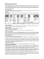
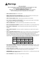
Operating Instructions and Parts Manual
JWS-22CS Spindle Shaper
WALTER MEIER (Manufacturing) Inc.
427 New Sanford Road
LaVergne, Tennessee 37086
Ph.: 800-274-6848
www.waltermeier.com
Part No. M-708320
Revision G1 08/2010
Copyright © 2010 Walter Meier (Manufacturing) Inc.
Warranty and Service
Walter Meier (Manufacturing) Inc., warrants every product it sells. If one of our tools needs service or repair, one of
our Authorized Service Centers located throughout the United States can give you quick service. In most cases, any
of these Walter Meier Authorized Service Centers can authorize warranty repair, assist you in obtaining parts, or
perform routine maintenance and major repair on your JET ® tools. For the name of an Authorized Service Center in
your area call 1-800-274-6848.
MORE INFORMATION
Walter Meier is consistently adding new products to the line. For complete, up-to-date product information, check with
your local Walter Meier distributor, or visit waltermeier.com.
WARRANTY
JET products carry a limited warranty which varies in duration based upon the product (MW = Metalworking, WW =
Woodworking).
WHAT IS COVERED?
This warranty covers any defects in workmanship or materials subject to the exceptions stated below. Cutting tools,
abrasives and other consumables are excluded from warranty coverage.
WHO IS COVERED?
This warranty covers only the initial purchaser of the product.
WHAT IS THE PERIOD OF COVERAGE?
The general JET warranty lasts for the time period specified in the product literature of each product.
WHAT IS NOT COVERED?
Five Year Warranties do not cover woodworking (WW) products used for commercial, industrial or educational
purposes. Woodworking products with Five Year Warranties that are used for commercial, industrial or education
purposes revert to a One Year Warranty. This warranty does not cover defects due directly or indirectly to misuse,
abuse, negligence or accidents, normal wear-and-tear, improper repair or alterations, or lack of maintenance.
HOW TO GET SERVICE
The product or part must be returned for examination, postage prepaid, to a location designated by us. For the name
of the location nearest you, please call 1-800-274-6848.
You must provide proof of initial purchase date and an explanation of the complaint must accompany the
merchandise. If our inspection discloses a defect, we will repair or replace the product, or refund the purchase price,
at our option. We will return the repaired product or replacement at our expense unless it is determined by us that
there is no defect, or that the defect resulted from causes not within the scope of our warranty in which case we will,
at your direction, dispose of or return the product. In the event you choose to have the product returned, you will be
responsible for the shipping and handling costs of the return.
HOW STATE LAW APPLIES
This warranty gives you specific legal rights; you may also have other rights which vary from state to state.
LIMITATIONS ON THIS WARRANTY
WALTER MEIER (MANUFACTURING) INC., LIMITS ALL IMPLIED WARRANTIES TO THE PERIOD OF THE
LIMITED WARRANTY FOR EACH PRODUCT. EXCEPT AS STATED HEREIN, ANY IMPLIED WARRANTIES OR
MERCHANTABILITY AND FITNESS ARE EXCLUDED. SOME STATES DO NOT ALLOW LIMITATIONS ON HOW
LONG THE IMPLIED WARRANTY LASTS, SO THE ABOVE LIMITATION MAY NOT APPLY TO YOU.
WALTER MEIER SHALL IN NO EVENT BE LIABLE FOR DEATH, INJURIES TO PERSONS OR PROPERTY, OR
FOR INCIDENTAL, CONTINGENT, SPECIAL, OR CONSEQUENTIAL DAMAGES ARISING FROM THE USE OF
OUR PRODUCTS. SOME STATES DO NOT ALLOW THE EXCLUSION OR LIMITATION OF INCIDENTAL OR
CONSEQUENTIAL DAMAGES, SO THE ABOVE LIMITATION OR EXCLUSION MAY NOT APPLY TO YOU.
Walter Meier sells through distributors only. The specifications in Walter Meier catalogs are given as general
information and are not binding. Members of Walter Meier reserve the right to effect at any time, without prior notice,
those alterations to parts, fittings, and accessory equipment which they may deem necessary for any reason
whatsoever. JET ® branded products are not sold in Canada by Walter Meier.
2
Table of Contents
Warranty and Service..........................................................................................................................2
Table of Contents ...............................................................................................................................3
Warning .............................................................................................................................................4
Electrical Connections.........................................................................................................................6
Introduction ........................................................................................................................................7
Specifications .....................................................................................................................................7
Unpacking and Cleanup ......................................................................................................................8
Adjustments .......................................................................................................................................9
Arbor Removal and Installation .........................................................................................................9
Collet Installation ........................................................................................................................... 10
Fence Adjustments ........................................................................................................................ 10
Table Ring Removal and Installation ............................................................................................... 11
Operation ......................................................................................................................................... 11
Spindle Control ............................................................................................................................. 11
Using the Fence as a Guide ........................................................................................................... 11
Shaping with Collars and Starting Pin ............................................................................................. 12
Collar Positioning .......................................................................................................................... 12
Starting Pin ................................................................................................................................... 13
Lubrication .................................................................................................................................... 13
Replacement Parts ........................................................................................................................... 15
Table and Fence Breakdown.......................................................................................................... 16
Cabinet Breakdown ....................................................................................................................... 17
Parts List ...................................................................................................................................... 18
Electrical Schematic ...................................................................................................................... 21
Electrical Schematic for the Forward/Reverse Switch....................................................................... 22
3
Warning
Wear eye protection.
Be sure keyed washer is directly under the spindle nut and the spindle nut is tight.
Feed the workpiece against the rotation of the cutter.
Do not use awkward hand positions.
Keep fingers away from the revolving cutter. Use fixtures when necessary.
Use the overhead guard when the adjustable fence is not in place.
•
KEEP GUARDS IN PLACE and in working order.
•
REMOVE ADJUSTING KEYS AND WRENCHES. Form a habit of checking to see that keys and
adjusting wrenches are removed from the machine before turning it on.
•
KEEP THE WORK AREA CLEAN. Cluttered areas and benches invite accidents.
•
DON’T USE IN A DANGEROUS ENVIRONMENT. Don’t use power tools in damp or wet locations,
or expose them to rain. Keep work area well lighted.
•
KEEP CHILDREN AWAY. All visitors should be kept a safe distance from the work area.
•
MAKE THE WORKSHOP KIDPROOF with padlocks, master swatches, or by removing starter keys.
•
DON’T FORCE THE MACHINE. It will do the job better and safer at the rate for which it was
designed.
•
USE THE RIGHT MACHINE. Don’t force a machine or attachment to do a job for which it was not
designed.
•
USE THE PROPER EXTENSION CORD. Make sure your extension cord is in good condition. When
using an extension cord, be sure to use one heavy enough to carry the current your machine will
draw. An undersized cord will cause a drop in the line voltage resulting in power loss and
overheating. The table below shows the correct size to use depending on cord length and nameplate
ampere rating. If in doubt, use the next heavier gauge. The smaller the gauge, the heavier the cord.
Volts
Total Length of Cord in Feet
120V
25
50
100
150
240V
50
100
200
300
14
12
AWG
16
16
•
WEAR PROPER APPAREL. Do not wear loose clothing, gloves, neckties, rings, bracelets, or other
jewelry which may get caught in moving parts. Nonslip footwear is recommended. Wear protective
hair covering to contain long hair.
•
ALWAYS USE SAFETY GLASSES. Also use face or dust masks if the cutting operation is dusty.
Everyday eyeglasses only have impact resistant lenses; they are not safety glasses.
•
SECURE WORK. Use clamps or a vise to hold work when practical. It’s safer than using your hand
and it frees both hands to operate the tool.
•
DON’T OVERREACH. Keep proper footing and balance at all times.
4
•
MAINTAIN TOOLS WITH CARE. Keep tools sharp and clean for best and safest performance.
Follow instructions for lubricating and changing accessories.
•
ALWAYS DISCONNECT THE MACHINE FROM THE POWER SOURCE BEFORE SERVICING.
•
REDUCE THE RISK OF UNINTENTIONAL STARTING. Make sure the switch is in the off position
before plugging in.
•
USE RECOMMENDED ACCESSORIES. Consult the operator’s manual for recommended
accessories. The use of improper accessories may cause risk of injury to persons.
•
NEVER STAND ON A MACHINE. Serious injury could occur if the machine tips or if the blade/cutter
is unintentionally contacted.
•
CHECK DAMAGED PARTS. Before further use of the machine, a guard or other part that is
damaged should be carefully checked to determine that it will operate properly and perform its
intended function - check for alignment of moving parts, binding of moving parts, breakage of parts,
mounting, and any other conditions that may affect its operation. A guard or other part that is
damaged should be properly repaired or replaced.
•
DIRECTION OF FEED. Feed work into the cutter against the direction of rotation of the cutter only.
•
NEVER LEAVE THE MACHINE RUNNING UNATTENDED. TURN POWER OFF. Don’t leave the
machine until it comes to a complete stop.
•
DO NOT OPERATE this machine while tired or under the influence of drugs, alcohol or any
medication.
•
DUST CAUTION. Some dust created by power sanding, sawing, grinding, drilling and other
construction activities contains chemicals known to cause cancer, birth defects or other reproductive
harm. Some examples of these chemicals are:
•
Lead from lead based paint.
•
•
Crystalline silica from bricks, cement and other masonry products.
Arsenic and chromium from chemically treated lumber.
Your risk of exposure varies, depending on how often you do this type of work. To reduce your
exposure to these chemicals, work in a well-ventilated area and work with approved safety
equipment, such as face or dust masks that are specifically designed to filter out microscopic
particles.
Familiarize yourself with the following safety notices used in this manual:
This means that if precautions are not heeded, it may result in minor injury and/or
possible machine damage.
This means that if precautions are not heeded, it may result in serious or even fatal
injury.
- - SAVE THESE INSTRUCTIONS - -
5
Electrical Connections
Electrical connections must
be made by a qualified electrician in
compliance with all relevant codes. This
machine must be properly grounded to help
prevent electrical shock and possible fatal
injury.
230 Volt Operation
If 230V, single phase operation is desired, the
following instructions must be followed:
1. Disconnect the machine from the power
source.
2. This shaper is supplied with six motor leads
that are connected for 115V operation, as
shown in Figure C. Reconnect these six
motor leads for 230V operation, as shown
in Figure D.
3. The 115V attachment plug, supplied with
the shaper, must be replaced with a
UL/CSA listed plug suitable for 230V
operation. This plug is illustrated in Fig. E.
Contact your local Authorized JET Service
Center or qualified electrician for proper
procedures to install the plug. The shaper
must comply with all local and national
codes after the 230 volt plug is installed.
4. The shaper with a 230 volt plug should only
be connected to an outlet having the same
configuration as illustrated by the grounded
outlet box in Figure E. No adapter is
available or should be used with the 230
volt plug.
115 Volt Operation
As received from the factory, your shaper is
ready to run at 115 volt operation. This shaper,
when wired for 115 volt, is intended for use on a
circuit that has an outlet and a plug that looks
the one illustrated in Figure A. A temporary
adapter, which looks like the adapter as
illustrated in Figure B, may be used to connect
this plug to a two-pole receptacle, as shown in
Figure B if a properly grounded outlet is not
available. The temporary adapter should only be
used until a properly grounded outlet can be
installed by a qualified electrician. This adapter
is not applicable in Canada.
The green
colored rigid ear, lug, or tab, extending from the
adapter, must be connected to a permanent
ground such as a properly grounded outlet box,
as shown in Figure B.
Figure C
Figure A
Figure D
Figure B
Important: In all cases (115 or 230 volts), make
certain the receptacle in question is properly
grounded. If you are not sure, have a registered
electrician check the receptacle.
Figure E
6
Introduction
The JET JWS-22CS woodworking shaper you have purchased is a high quality machine tool that will give
you years of superior service. You will get maximum performance and enjoyment from your new shaper if
you will take a few moments now to review the entire manual before beginning assembly and operation.
Become familiar with the details of operation.
The JET JWS-22CS, as well as all JET products, are backed by a nationwide network of authorized
distributors and/or service centers. Please contact your nearest distributor should you require parts or
service. Parts are also available directly from Walter Meier (Manufacturing) Inc., by calling 1-800-2746848.
Now that you have purchased a shaper, it is a good time to consider a dust collection system. See your
local JET distributor for the complete line of dust collectors and the full line of JET Dust Collector Hoses
and Accessories. Customize your installation and obtain maximum performance with JET dust hoods,
hoses, clamps, fittings, and blast gates.
Specifications
Model Number ..................................................................................................................... JWS-22CS
Stock Number .......................................................................................................................... 708320
Cutterhead Speed(reversible)(RPM) ........................................................................ 7,000 & 9,000 RPM
Table Size (in.) .............................................................................................................. 18-1/8 x 22-1/4
Table Slot (in.) ................................................................................................................3/4 x 3/8 T-slot
Table Opening Diameter (in.)......................................................................................................... 5-1/4
Insert Opening Diameter (in.).......................................................................................... 1-5/8 and 3-1/4
Fence Size (2) (in.) ................................................................................................................ 10 x 3-1/8
Spindle Capacity (in.) ........................................................................................................... 1/2 and 3/4
Router Bit Collet Capacity (in.) .............................................................................................. 1/4 and 1/2
Under Nut Capacity (in.) ..........................................................1/2" Spindle: 2-1/2 ; 3/4" Spindle: 2-15/16
Spindle Travel (in.)...................................................................................................................... 1-7/16
Table Height (in.) ........................................................................................................................ 33-1/2
Overall Dimensions (in.) ......................................................................... 22-1/4 W x 25-1/2 D x 38-1/2 H
Dust Chute Diameter (in.) .................................................................................................................... 4
Motor ......................................................TEFC, 1 1/2 HP, 1Ph, 115/230V (prewired 115V), 12/6 A, 60Hz
Net Weight (approx.) ................................................................................................................. 192 lbs.
Shipping Weight (approx.) ......................................................................................................... 210 lbs.
The above specifications were current at the time this manual was published, but because of our policy of
continuous improvement, Walter Meier reserves the right to change specifications at any time and without
prior notice, without incurring obligations.
7
Unpacking and Cleanup
1. Finish removing all contents from the
shipping container. Do not discard any
shipping material until the shaper is set up
and running.
2. Inspect contents for shipping damage and
report any damage or missing parts to your
distributor.
3. Clean all protected parts with kerosene. Do
not use gasoline, paint thinner, or any
cellulose-based solvent. These will damage
painted surfaces and melt plastic.
Tools Required for Assembly
10mm Wrench
14mm Wrench
Contents of the Shipping Container
1
Shaper
Accessory Package
1 Dust Chute
1 Miter Gauge
1 Switch Lock Bracket
1 ¾” Spindle Assembly
1 ¼” Collet w/Nut
1 ½” Collet w/Nut
1 Collet Nut
1 Spanner Wrench
1 8mm Hex Wrench
1 6mm Hex Wrench
1 3mm Hex Wrench
Dust Chute Assembly
1.
Install dust chute to the fence body with
two ¼” x ½” hex cap bolts.
8
Adjustments
Arbor Removal and Installation
All adjustments to the
machine must be made with the power off
and unplugged from the power source.
Failure to comply may result in serious
injury.
Figure 1
The safety shield has been
removed for illustration purposes only!
Never operate the shaper without the safety
shield. Failure to comply may result in
serious injury.
The arbor is mounted to the main spindle with a
draw bar and a nut. Use the following procedure
to remove the arbor. Reverse the steps to install
the arbor.
1. Disconnect the machine from the power
source.
Figure 2
2. Raise the spindle fully by turning handwheel
clockwise.
3. Open the door by pulling out the latch (A,
Fig. 1). Open the door, and release the
latch.
4. Pull the spindle locking mandrel (A, Fig. 2)
out, and turn to lock the main spindle.
5. Loosen the draw bar nut (B, Fig. 2) with a
14mm box wrench or adjustable wrench and
remove the nut (A, Fig. 3).
6. Loosen the hex nut (A, Fig. 4) with the arbor
wrench (B, Fig. 3).
Figure 3
7. Loosen and remove the spindle (C, Fig. 3).
8. Remove the nut (A, Fig. 4) and draw bar (D,
Fig. 3) from the spindle.
9. Pull the spindle locking mandrel out and turn
to release the main spindle.
10. Close the door.
Figure 4
9
Collet Installation
1. Disconnect machine from the power
source.
2. To set up the shaper for collet use, remove
the arbor and clean the spindle taper (Fig.
5).
3. Raise the spindle fully by turning handwheel
clockwise.
4. Pull the spindle locking mandrel out (A, Fig.
2) and turn to lock the main spindle.
5. Screw the collet assembly onto the spindle
threads (Fig. 6)
Figure 5
6. Insert a router bit into the collet.
7. Tighten the collet nut with the arbor wrench.
8. Pull the spindle locking mandrel out and turn
to release the main spindle.
Fence Adjustments
1. Adjust fence halves by loosening lock knob
(A, Fig. 7), turn knurled knob (B, Fig. 7) to
adjust fence in or out, and tighten lock knob.
2. Adjust spindle guard height by loosening
wing nut (C, Fig. 7), sliding guard up or
down to desired height, and then tightening
wing nut.
3. Adjust spindle guard depth by loosening two
lock knobs (D, Fig. 7), moving spindle guard
to desired position, and then tightening two
lock knobs.
Figure 6
4. Hold down clamps can be adjusted for
height by loosening hex socket cap screws
(E, Fig. 7), adjusting the hold down clamps
to the desired height, and tightening the hex
socket cap screws.
Figure 7
10
Table Ring Removal and Installation
To remove the table ring(s):
1. Remove any collet or spindle assembly in
the spindle.
2. Lower the spindle assembly completely.
3. Loosen and remove the three 1/4" x 5/8”
cross point screws from the ring.
4. Lift ring.
5. Install the rings back into the table using the
“witness” line (alignment indicator line) on
the table and the table rings.
Operation
Spindle Control
To raise or lower spindle:
1. Loosen spindle lock handle counter
clockwise (A, Fig. 8). The handle is springloaded; by pulling out you can adjust the
positioning.
2. Raise or lower spindle to desired height by
turning handwheel (B, Fig. 8).
Figure 8
3. Tighten spindle lock handle clockwise.
Using the Fence as a Guide
Shaping with the fence is the safest and most
satisfactory method of working. This method
should always be used when work permits.
Almost all straight work can be used with the
fence.
Figure 9
1. For most work, where a portion of the edge
of the work is not touched by the cutter, both
the front and rear fences are in a straight
line, as shown in Figure 9.
2. When the shaping operation removes the
entire edge of the work (i.e. jointing or
making a full bead), the shaped edge will
not be supported by the rear fence when
both fences are in line as shown in Figure
10. In this case, the work piece should be
advanced to the position shown in Figure 10
and stopped.
Figure 10
3. The rear fence should be advanced to
contact the work as shown in Figure 11. The
rear fence will then be in line with the cutting
circle.
Figure 11
11
Shaping with Collars and Starting Pin
Follow these rules when shaping with collars
and starting pin for safest operation and best
results:
1. Collars must be smooth and free from all
gum or other substances.
Figure 12
2. The edge of the work must be smooth. Any
irregularity in the surface which rides
against the collar will be duplicated on the
shaped surface.
3. A portion of the work's edge must remain
untouched by the cutter so that the collar
will have sufficient bearing surface. See
Figure 12 for an example of insufficient
bearing surface. Figure 13 illustrates
sufficient bearing surface.
Figure 13
4. The work must be fairly heavy in proportion
to the cut being made. See Figure 14.
Under no circumstances should a small
workpiece be shaped against the collars as
shown in Figure 15.
Figure 14
Figure 15
Collar Positioning
Collars may be positioned above, below, or
between two cutters:
1. When using the collar below the cutter,
Figure 16, the progress of the cut can be
observed at all times. A disadvantage of
this method is any accidental lifting of the
work will gouge the wood and ruin the
workpiece.
Figure 16
2. Using the collar above the cutter, Figure 17,
offers the advantage of the cut not being
affected by slight variations in the stock's
thickness. However, the cut is not visible
during the operation. Another advantage is
accidental lifting of the work piece will not
gouge the work piece. Simply correct the
mistake by repeating the operation.
Figure 17
12
3. The collar between cutters method, shown
in Figure 18, has both the advantages and
disadvantages of the first two methods.
This method is used primarily where both
edges of the work are to be shaped.
Starting Pin
Figure 18
Using the starting pin should
only be attempted by advanced users! If you
have never used this method before, it is
recommended you get training from a
qualified person who is knowledgeable in
starting pin shaping!
Failure to comply may cause serious injury!
The starting pin is placed in one of the threaded
holes in the table:
1. Work should be placed in the first position
using the guide pin as support, as shown in
Figure 19. Then swing the work into the
cutter as shown in the second position. The
work will now be supported by the collar and
starting pin.
Figure 19
2. After the cut has been started, the work is
swung free of the starting pin and rides only
against the collar as shown in the third
position in Figure 20. Always feed against
the action of the cutter.
Lubrication
To insure easy movement when raising and
lowering spindle, occasionally apply a drop of
light oil on outside of spindle cartridge.
Figure 20
Spindle cartridge bearings are pre-lubricated
and sealed. They need no further care.
13
Troubleshooting
Trouble
Shaper will not start.
Overload kicks out
frequently.
Cutter does not come
up to full speed.
Cuts are
unsatisfactory
Probable Cause
Remedy
Cord unplugged from the power
source.
Plug in power cord.
Fuse blown, or circuit breaker tripped.
Replace fuse, or reset circuit breaker.
Cord damaged.
Replace cord.
Reversing switch is in the OFF
position.
Turn switch to forward or reverse.
Overload tripped.
Reset overload by depressing red
stop button.
Extension cord or wiring inadequate
size.
Replace cord or wiring with proper
gauge wiring.
Feeding stock too fast.
Reduce stock feed rate.
Cutter head is dull.
Use only sharp cutters.
Shop wire gauge is too small.
Replace cord or wiring with proper
gauge wire.
Extension cord too light or too long.
Replace with adequate size cord.
Power source is not adequate.
Contact local electrical utility.
Motor not wired for correct voltage.
Refer to motor name plate for correct
wiring.
Spindle is locked with mandrel lever.
Unlock spindle - see label next to
lever on base.
Dull cutter.
Replace cutter.
Gum or pitch on cutter.
Remove cutter and clean with solvent.
Cutterhead rotating in the wrong
direction.
Check for proper rotation at start up.
Feeding work in the wrong direction.
Feed work against the cutter rotation.
Cutterhead damaged.
Replace cutterhead.
Stand on uneven surface.
Stand must rest solidly on level
surface, bolt to floor if necessary.
Defective V-belt.
Replace V-belt.
V-belt incorrectly tensioned.
Apply proper tension.
Bent pulley.
Replace pulley.
Motor mounted improperly.
Motor must be properly mounted with
snug nuts and bolts.
Machine vibrates.
Edge splits off on
cross grain cut.
Characteristic of this type of cut.
Make cross grain cuts first, then finish
cut with the grain.
Use scrap block to support end of cut.
14
Trouble
Probable Cause
Remedy
Raised areas on
shaped edge.
Variation of pressure holding work
against cutter.
Hold work firmly against table and
fence. Use hold-downs.
Work pulled from
hand.
Feeding work in the wrong direction.
Always feed work against the rotation
of the cutterhead.
Fence misalignment.
Align outfeed fence.
Side pressure not uniform.
Use holddowns; keep constant
pressure against fence.
Cutting too deep on one pass.
On hardwoods take light cuts; attain
full depth with several passes.
Forcing work.
Feed work slowly and steadily.
Depth of cut not
uniform.
Work burns.
Cut height not
uniform.
Cuts not smooth.
Spindle does not
raise freely.
Wrong R.P.M.
Keep pressure firm throughout pass.
Use hold-downs. Make pass slowly
and steadily. Keep work under cutter
whenever possible.
Use faster speed.
Feeding too fast.
Slow feed speed.
Working against the grain.
Work with the grain whenever
possible.
Cutting too deep on one pass.
Take several passes on very deep
cuts.
Sawdust or dirt in raising mechanism.
Brush or blow out dirt and saw dust.
Lubricate regularly.
Variation in pressure holding work to
table.
Replacement Parts
Replacement parts are listed on the following pages. To order parts or reach our service department, call
1-800-274-6848, Monday through Friday (see our website for business hours, www.waltermeier.com).
Having the Model Number and Serial Number of your machine available when you call will allow us to
serve you quickly and accurately.
15
Table and Fence Breakdown
16
Cabinet Breakdown
17
Parts List
Index No. Part No.
Description
Size
Qty
1 .............. JWS22CS-1 ............Table ................................................................................................. 1
2 .............. JWS22CS-2 ............Spindle Housing ................................................................................. 1
2-1 ........... JWS22CS-2-1 .........Spindle Locking Mandrel ..................................................................... 1
2-2 ........... JWS22CS-2-2 .........Lock Washer ....................................................M18.5 ........................ 1
3 .............. JWS18HO-3 ............Cutter Spindle Bracket ........................................................................ 1
4 .............. BB-6005ZZ ..............Ball Bearing........................................................................................ 2
4-1 ........... JWS18HO-4-1 .........Wave Washer..................................................................................... 1
5 .............. JWS18HO-5 ............Snap Ring .......................................................................................... 1
6 .............. JWS22CS-6 ............Pulley................................................................................................. 1
7 .............. TS-0561082 ............Hex Nut............................................................3/4x16UNF ................. 1
8 .............. JWS22CS-8 ............Main Spindle ...................................................................................... 1
8-1 ........... JWS18HO-8-1 .........Shaft (1/2) .......................................................................................... 1
................ JWS18HO-8-1A .......Shaft ** (3/4-not shown) ...................................................................... 1
9 .............. JWS22CS-9 ............Key .................................................................................................... 1
10 ............ JWS18HO-10 ..........Snap Ring (spindle housing) ................................................................ 1
10-1 ......... JWS18HO-10-1 .......Snap Ring (main spindle) .................................................................... 1
10-2 ......... OS-25478................Oil Seal .............................................................................................. 1
11 ............ JWS18HO-11 ..........Hex Nut (spindle) ................................................................................ 1
11-1 ......... JWS18HO-11-1 .......Table Ring (serial # 0092192 and lower) .............................................. 1
11-1 ......... JWS18HO-11-1N.....Table Ring (serial # 0092193 and higher) ............................................. 1
11-2 ......... JWS18HO-11-2 .......Table Ring ......................................................................................... 1
11-3 ......... JSL10TS-7 ..............Phillip’s Screw ..................................................1/4"x5/8” .................... 3
12 ............ JWS18HO-12 ..........Spacer (1/2) .....................................................80 .............................. 1
................ JWS18HO-12A ........Spacer ** (3/4-not shown) .................................1.00 ........................... 1
13 ............ JWS18HO-13 ..........Spacer (1/2) .....................................................60 .............................. 1
................ JWS18HO-13A ........Spacer ** (3/4-not shown) .................................75 .............................. 1
14 ............ JWS18HO-14 ..........Spacer (1/2) .....................................................40 .............................. 1
14A.......... JWS18HO-14A ........Spacer ** (3/4-not shown) .................................0.50 ........................... 1
15 ............ JWS18HO-15 ..........Fixed Bushing (1/2)............................................................................. 1
................ JWS18H0-15A .........Fixed Bushing ** (3/4-not shown) ......................................................... 1
16 ............ JWS18HO-16 ..........Washer (1/2) ...................................................................................... 1
................ JWS18HO-16A ........Washer ** (3/4-not shown) .................................................................. 1
17 ............ TS-0208061 ............Hex Cap Bolt (1/2) ............................................5/16x1........................ 1
................ TS-0209051 ............Hex Cap Bolt ** (3/4-not shown) ........................3/8x1 ......................... 1
18 ............ JWS18HO-18 ..........Quill ................................................................................................... 1
18-1 ......... JWS18HO-18-1 .......Nut ..................................................................1/2-20 UNF ................ 1
19 ............ TS-0561021 ............Hex Nut............................................................5/16 ........................... 1
20 ............ TS-0051031 ............Hex Head Bolt ..................................................5/16x5/8 ..................... 1
21 ............ JWS18HO-21 ..........Lock Washer ....................................................1/2 ............................. 3
22 ............ TS-0070041 ............Hex Cap Bolt ....................................................1/2x1-3/4 .................... 3
23 ............ JWS22CS-23...........Lock Bar ............................................................................................ 1
25 ............ JSL10TS-6 ..............Guide Plate ........................................................................................ 1
26 ............ JSL10TS-3 ..............Miter Gauge Body ............................................................................... 1
27 ............ JWS18HO-27 ..........Plate .................................................................................................. 1
27-1 ......... JWS18HO-27-1 .......Flat Head Screw ...............................................3/16x1/4 ..................... 1
27-2 ......... JWS18HO-27-2 .......Washer (special)................................................................................. 1
28 ............ JWS18HO-28 ..........Washer .............................................................................................. 1
29 ............ JSL10TS-1 ..............Knob .................................................................................................. 1
30 ............ JWS18HO-30 ..........Screw ..............................................................3/16x1/4 ..................... 1
31 ............ JWS22CS-31...........Spring Pin ........................................................M3x19........................ 1
32 ............ JWS22CS-32...........Lock Handle ....................................................................................... 1
33 ............ TS-0680041 ............Lock Washer ....................................................1/4 ............................. 2
34 ............ JWS22CS-34...........Motor Cover ....................................................................................... 1
35 ............ JWS22CS-35...........Cabinet Cover .................................................................................... 1
Note: (1/2) and (3/4) refer to 1/2" or 3/4" spindles
18
Index No. Part No.
Description
Size
Qty
36 ............ JTAS10-45 ..............Handle ............................................................................................... 1
37 ............ TS-0720091 ............Lock Washer ....................................................3/8 ............................. 4
38 ............ TS-1540021 ............Hex Nut............................................................M6 ............................. 1
39 ............ JTAS10-41 ..............Spring ................................................................................................ 1
40 ............ TS-1482101 ............Hex Cap Screw ................................................M6x50........................ 1
41 ............ JWS22CS-41...........Motor Plate......................................................................................... 1
42 ............ TS-0208061 ............Hex Cap Bolt ....................................................5/16x1........................ 6
43 ............ TS-0680031 ............Washer ............................................................5/16 ........................... 9
44 ............ TS-0720081 ............Lock Washer ....................................................5/16 ........................... 8
45 ............ TS-0561021 ............Hex Nut............................................................5/16 ........................... 6
46 ............ JWS22CS-46...........Motor ................................................................................................. 1
47 ............ JWS18HO-47 ..........Motor Pulley ....................................................................................... 1
48 ............ JWS18HO-48 ..........Key .................................................................................................... 1
49 ............ JWS18HO-49 ..........Set Screw ........................................................1/4x3/8....................... 1
50 ............ JWS22CS-50...........Washer ............................................................5/16x18 ...................... 5
51 ............ TS-0081031 ............Hex Cap Screw ................................................5/16x3/4 ..................... 2
52 ............ JWS22CS-52...........Motor Plate Bracket ............................................................................ 1
53 ............ VB-M23 ...................V-Belt................................................................................................. 1
54 ............ JWS22CS-54...........Feed Bar ............................................................................................ 1
55 ............ JWS18HO-55 ..........Spring Pin ........................................................M3x18........................ 1
56 ............ JWS18HO-56 ..........Handle ............................................................................................... 1
57 ............ TS-0680021 ............Washer ............................................................1/4 ............................. 1
58 ............ TS-0050021 ............Hex Cap Bolt ....................................................1/4 x 5/8 ..................... 1
59 ............ JWS18HO-59 ..........Switch Assembly (includes #61,62,63,64,107,109)................................ 1
59-2 ......... JWS22CS-59-2........Strain Relief ....................................................................................... 3
59-3 ......... JWS18HO-59-3 .......Switch Cover ...................................................................................... 1
59-4 ......... JWS22CS-59-4........Plate .................................................................................................. 1
60 ............ JWS22CS-60...........Cabinet .............................................................................................. 1
61 ............ JWS18HO-61 ..........Plate .................................................................................................. 1
62 ............ JWS18HO-62 ..........Screw ................................................................................................ 4
63 ............ JWS18HO-63 ..........Switch Plate ....................................................................................... 1
64 ............ JWS18HO-64 ..........Switch Handle .................................................................................... 1
65 ............ JWS22CS-65...........Power Cord ........................................................................................ 1
66 ............ JTAS10-28 ..............Tap Screw........................................................M5x10........................ 4
67 ............ JWS22CS-67...........Draw Bar..........................................................5/16x6........................ 1
67-1 ......... JWS22CS-67-1........Taper Nut ........................................................................................... 1
68 ............ JWS22CS-68...........Strain Relief ....................................................................................... 2
69 ............ JWS22CS-69...........Cord Plate .......................................................................................... 1
70 ............ JTAS10-47 ..............Cord Clamp Plate ............................................................................... 1
71 ............ JWS22CS-71...........Power Cord Sleeve ............................................................................. 1
72 ............ JWS22CS-72...........Foam Strip ......................................................................................... 1
73 ............ JWS22CS-73...........Rubber Padding ................................................................................. 2
74 ............ JWS18HO-74 ..........Fence (right) ....................................................................................... 1
74-1 ......... JWS18HO-74-1 .......Fence (left)......................................................................................... 1
75 ............ JWS18HO-75 ..........Guide Bar........................................................................................... 2
76 ............ TS-0680031 ............Washer ............................................................5/16 ........................... 2
77 ............ JWS18HO-77 ..........Flat Head Machine Screw .................................5/16x1-3/4 .................. 2
77-1 ......... TS-0561021 ............Hex Nut............................................................5/16 ........................... 2
78 ............ JWS18HO-78 ..........Lead Screw ........................................................................................ 2
79 ............ TS-0050031 ............Hex Cap Bolt ....................................................1/4x3/4....................... 2
80 ............ JWS18HO-80 ..........Guide Plate ........................................................................................ 2
81 ............ JWS18HO-81 ..........Slide Block ......................................................................................... 2
82 ............ JWS18HO-82 ..........Guide Plate Support............................................................................ 2
83 ............ TS-0060051 ............Hex Cap Bolt ....................................................3/8x1 ......................... 1
19
Index No. Part No.
Description
Size
Qty
84 ............ JWS18HO-84 ..........Safety Shield ...................................................................................... 1
85 ............ JWS18HO-85 ..........Fence Body ........................................................................................ 1
86 ............ TS-0209021 ............Hex Socket Cap Bolt .........................................3/8x5/8....................... 2
87 ............ JWS18HO-87 ..........Lock Knob ........................................................3/8 ............................. 2
88 ............ JWS18HO-88 ..........Knob .................................................................................................. 2
89 ............ TS-0680061 ............Washer ............................................................1/2 ............................. 2
90 ............ JWS18HO-90 ..........Lock Handle ....................................................................................... 2
90-1 ......... JWS18HO-90-1 .......Handle .............................................................1/4 ............................. 2
90-2 ......... JWS18HO-90-2 .......Round Knob .....................................................1/4 ............................. 4
91 ............ TS-0050051 ............Hex Cap Bolt ....................................................1/4x1/2....................... 2
92 ............ JWS18HO-92 ..........Safety Shield Mount ............................................................................ 1
93 ............ TS-0680031 ............Washer ............................................................5/16 ........................... 2
94 ............ JWS18HO-94 ..........Knob ................................................................5/16x1........................ 2
95 ............ TS-0680041 ............Washer ............................................................3/8 ............................. 1
96 ............ JWS18HO-96 ..........Butterfly Nut ....................................................................................... 1
97 ............ JWS18HO-97 ..........Label ................................................................................................. 1
98 ............ JWS18HO-98 ..........Warning Label .................................................................................... 1
99 ............ JWS18HO-99 ..........Motor Name Plate ............................................................................... 1
100 .......... JWS18HO-100 ........Stop Pin ............................................................................................. 2
101 .......... JWS18HO-101 ........Dust Chute ......................................................................................... 1
102 .......... JWS22CS-102 .........Spanner Wrench ** ............................................................................ 1
103 .......... JWS22CS-103 .........Collet w/Nut** ..................................................1/4 ............................. 1
104 .......... JWS22CS-104 .........Collet w/Nut** ..................................................1/2 ............................. 1
105 .......... JWS22CS-105 .........Motor Cord ......................................................................................... 1
106 .......... TS-0207021 ............Hex Cap Bolt ....................................................1/4x1/2....................... 4
107 .......... JWS18HO-107 ........Screw ................................................................................................ 1
108 .......... JWS22CS-108 .........Lock Out Bracket ................................................................................ 1
109 .......... JWS18HO-109 ........Nut .................................................................................................... 6
110 .......... JWS22CS-110 .........I.D. Label ........................................................................................... 1
111 .......... JWS22CS-111 .........Label (spindle direction) ...................................................................... 1
112 .......... JWS22CS-112 .........Label (spindle lock) ............................................................................. 1
................ JWS22CS-MGCP ....Miter Gauge Complete (includes # 25 thru 30) ...................................... 1
................ JWS22HO-HK .........Hardware Kit (shaper - not shown) ....................................................... 1
................ JWS18HO-FACP .....Fence Assy Complete (not shown)....................................................... 1
................ JWS22CS-AP ..........Accessory Package ............................................................................ 1
** included in JWS22CS-HK, Hardware Kit
20
Electrical Schematic
21
Electrical Schematic for the Forward/Reverse Switch
22
23
WALTER MEIER (Manufacturing) Inc.
427 New Sanford Road
LaVergne, Tennessee 37086
Phone: 800-274-6848
www.waltermeier.com
24