1
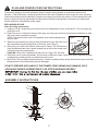
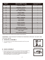
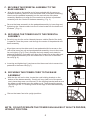
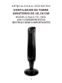
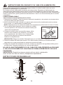
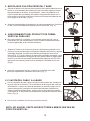
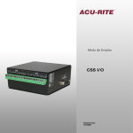
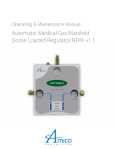
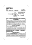
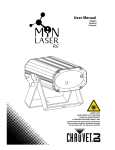
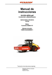
ITEM# 1000 026 993 40 inch Oscillating Tower Fan MODEL# FZ-18DL PLEASE READ AND SAVE THESE IMPORTANT INSTRUCTIONS 1 SAFETY INFORMATION When using electrical appliances, basic safety precautions should always be followed to reduce the risk of fire, electric shock and injury to persons, including the following: 1. Use fan only for intended use, as described in instruction manual. 2. To protect against electric shock, do not immerse unit, plug, or cord in water or spray with liquids. 3. Close supervision is necessary when any appliance is used by or near children. 4. Unplug from outlet when not in use, when moving fan from one location to another, before putting on or taking off parts and before cleaning. 5. Never insert fingers, pencils or any other objects through the grille when fan is running. 6. Disconnect fan before cleaning. 7. Make sure fan is on a stable surface when operating to avoid chance of overturning. 8. Do not use fan in a window. Rain may cause an electrical hazard. 9. Do not operate in the presence of explosive and/or flammable fumes. 10. Do not place fan or any parts near an open flame, cooking or other heating appliances. 11. Do not operate any appliance with a damaged cord or plug, after the appliance malfunctions or has been dropped or damaged in any manner. 12. To disconnect, grip plug and pull from wall outlet. Never yank on cord. 13. Always use on a dry surface. 14. This product is intended for household use only and not for commercial or industrial use. 15. Do not use fan near curtains, plants, window treatments, etc. 16. Do not operate any fan with a damaged cord or plug. Discard fan or return to an authorized service facility for examination and/or repair. 17. Do not run cord under carpeting. Do not cover cord with throw rugs, runners, or similar coverings. Do not route cord under furniture or appliances. Arrange cord away from traffic area and where it will not be tripped over. 18. WARNING: To reduce the risk of electric shock and injury to persons, do not use this fan near a door or window. 19. WARNING: To reduce the risk of fire or electric shock, do not use this fan with any solid-state speed control device. PLEASE READ AND SAVE THESE IMPORTANT SAFETY INSTRUCTIONS POLARIZED PLUG NOTE: This appliance has a polarized plug (one blade is wider than the other). The polarized plug is not intended to be used in non-polarized outlets (having both slots the same size). To reduce the risk of electric shock, this plug is intended to fit in a polarized outlet only one way. If the plug does not fit fully in the outlet, reverse the plug. If it still does not fit, contact a qualified electrician to install the proper outlet. Do not attempt to modify this plug or defeat this safety feature in any way. POWER CORD SAFETY TIPS 1. 2. 3. 4. Never pull or yank on the cord or the appliance. To insert plug, grasp it firmly and guide it into outlet. To disconnect appliance, grasp plug and remove it from outlet. Before each use, inspect the power cord for cuts and/or abrasion marks. If any are found, this indicates that the appliance should be serviced and the power cord replaced. Please return it to our Service Department or to an authorized Service Representative. 5. Never wrap the cord tightly around the appliance, as this could place undue stress on the cord where it enters the appliance and cause it to fray and break. 2 PLUG AND POWER CORD INSTRUCTIONS This product employs overload protection (fuse). A blown fuse indicates an overload or short-circuit situation. If the fuse blows, unplug the product from the outlet. Replace the fuse as per the user servicing instructions (follow product marking for proper fuse rating) and check the product. If the replacement fuse blows, a short-circuit may be present and the product should be discarded or returned to an authorized service facility for examination and/or repair. REPLACEABLE FUSE User Servicing Instructions 1. Unplug your fan. Grasp plug and remove from the receptacle or other outlet device. Do not unplug by pulling on cord. 2. Open fuse cover, located on the top of the plug, by using your thumb or a flat head screwdriver to slide the cover down towards the prongs. NOTE: Ensure that fuse cover is completely open before attempting to Figure 1 remove fuse. Fuse 3. Remove fuse carefully by using a small screwdriver to pry the fuse out of Fuse cover the compartment by the metal ends of the fuse. (see Figure 1) 4. Place plug on a solid, flat surface. Insert new 2.5 Amp, 125 Volt fuse into fuse compartment and use a small screwdriver to secure the metal ends of the fuse into the compartment. Metal ends CAUTION: Risk of fire. Replace fuse only with 2.5 Amp, 125 Volt fuse. 5. Slide fuse cover closed completely. If fuse cover is difficult to close, make sure fuse is secured in place completely by pressing down on metal ends of the fuse. 6. Risk of fire. Do not replace attachment plug. Contains a safety device (fuse) that should not be removed. Discard product if the attachment plug is damaged. DO NOT OPERATE APPLIANCE IF THE POWER CORD SHOWS ANY DAMAGE, OR IF APPLIANCE WORKS INTERMITTENTLY OR STOPS WORKING ENTIRELY. ASSEMBLY INSTRUCTIONS A B L C D M F K E O N G P H Q J I K 3 PART DESCRIPTION QUANTITY A B C D E F G H I J K L M N O P Q Control Panel Remote Control Fan Housing Air Output Grille Motor Base Power Cord Front Pedestal Rear Pedestal Front Base Rear Base Hand Screws Speed Button Timer Button Oscillation Button Power (On/Off) Button LED Light Wind Mode Button 1 1 1 1 1 1 1 1 1 1 4 1 1 1 1 1 1 Carefully remove all contents from the plastic bag and gift box. CAUTION: THIS FAN MUST OPERATE STANDING UPRIGHT. DO NOT USE WITHOUT BASE. Fig. 1 A. PEDESTAL ASSEMBLY Line up the front and rear pedestal assembly and firmly snap together. ( Fig. 1 ) Pedestal Assembly Fig. 2 B. BASE ASSEMBLY Pillars Align the two portions of the circular base and snap together by gently pushing the 4 pillars at the bottom of the Rear Base ( Fig.2, Rear Base )into the 4 adjacent sockets of the bottom of the front base( Fig. 2, Front Base ). Make sure two bases connected together closely and tightly. 4 Rear Front Base Adjacent Base Sockets C. SECURING THE PEDESTAL ASSEMBLY TO THE BASE ASSEMBLY Fig. 3 Align the arrow on the smaller end of rear pedestal with the arrow on the base assembly (which is near the central hole of the base assembly), then insert the pedestal assembly into the central hole of the base assembly. Make sure to align the 3 screw holes on bottom of pedestal assembly with the 3 holes in the base assembly. ( Fig. 3 ) Screw holes Fig. 4 Secure the base assembly to the pedestal assembly by inserting and tightening the 3 hand screws into the 3 holes located on the bottom of the base. ( Fig. 4 ) D. SECURING THE TOWER FAN TO THE PEDESTAL ASSEMBLY Carefully turn the fan on its side and place on a table. Back of fan body is upward. Place the power cord through the center of the pedestal and base assembly. Hand screws Fig. 5 Align the arrow on the wider end of rear pedestal with the arrow on the rear of the tower fan unit and push pedestal assembly close to the tower fan unit tightly (Fig.5).Firmly hold the fan body steady and rotate the pedestal assembly clockwise until align the screw hole on the wider end of the pedestal assembly with the screw hole on the rear of the tower fan unit(Fig.6). Fig. 6 Inserting and tightening 1 hand screw into the screw hole to secure the pedestal to the tower fan(Fig.7). Fig. 7 E. SECURING THE POWER CORD TO THE BASE ASSEMBLY With the fan still on its side, locate the cord holding bracket on the bottom of the base assembly. Gently pull any slack out of the power cord, place the power cord securely in the holding bracket and secure the power cord bracket over the power cord. Then thread the power cord through the “U” locating notch at the edge of the base assembly. ( Fig. 8) Hand screw Fig. 8 Return the tower fan to its upright position. NOTE: DO NOT OPERATE THE TOWER FAN UNLESS IT IS IN ITS PROPER, UPRIGHT POSITION. 5 DISPLAYED OPERATING INSTRUCTIONS Once fan is fully assembled (see assembly instructions section), place fan on a level and dry surface. Plug the power cord into a polarized 120 volt AC wall outlet. USING THE CONTROL PANEL AND REMOTE CONTROL This fan is equipped with 3 speeds, 3 breeze modes, a timer and remote. For your convenience, the buttons on the control panel of the fan operates the same functions as the remote control. BUTTON FUNCTION DISPLAYED /2 hr, 1hr, 2hr, 4hr. Example 1: 1/2 hr illuminated indicates the timer will shut 1 TIMER Pressing this button sets the timer in increments of 0.5 hour to a maximum of 7.5 hours. After the timer runs out, the fan will automatically shut off. off after 30 minutes. Example 2: 1/2 hr and 2hr illuminated indicates the timer will shut off after 2.5 hours. Example 3: 1/2 hr , 1hr, 2hr and 4hr illuminated indicates the timer will shut off after 7.5 hours. The light at this icon indicates the fan simulating a NATURAL breeze mode by cycling through all the speeds. MODE The light at this icon indicates the fan is simulating a softer breeze mode (SLEEP MODE) by cycling one speed higher and lower, ideal for resting. Pressing this button will cycle the fan through different patterns of breeze modes. and lights are OFF If both of the above lights are not illuminated the fan is operating on the NORMAL mode. SPEED Pressing this button will cycle the fan through 3 comfort speeds (High/ Medium/Low). This button can be used with any MODE. OSCILLATION To activate the oscillation function for widespread breeze distribution, press this oscillation button once. 1 2 3 These icons indicate the selected speed low, medium, high. The oscillation light on the fan will be illuminated when activated. Press button again to turn off the oscillation function. Oscillation can be controlled while the fan is operating. Use this button to turn the fan ON / OFF. ON/OFF REMOTE CONTROL BATTERY INSTALLATION/REPLACEMENT INSTRUCTIONS Fig. 9 A. When it is not in use, remote control may be placed in the small chamber of the back of the control panel. (Fig.9) B. Take out the Remote Control from the small Chamber of the back of the control panel. C. Remove battery door by sliding downward in direction of arrow. D. Insert 2 AAA batteries into the remote following the directional guides in the recessed slots. Batteries are not included. E. Replace battery door by sliding upward opposite of arow direction until door snaps in place. NOTE: DO NOT MIX OLD AND NEW BATTERIES. DO NOT MIX ALKALINE, STANDARD (CARBON-ZINC) OR RECHARGEABLE (NICKEL-CADMIUM) BATTERIES. SEE RECYCLER IN YOUR AREA FOR PROPER DISPOSAL OF BATTERIES. 6 CARE AND MAINTENANCE This appliance requires little maintenance and contains no user serviceable parts. Do not try to fix it yourself. Refer it to qualified service personnel if servicing is needed. This fan is permanently lubricated and will not require additional lubrication for the life of the fan. To clean: Ensure the fan is turned off and unplugged. Use only a soft cloth to gently wipe the outer surfaces of the fan clean. To clean between the grilles and fan blade area, we recommend using a pipe cleaner, flexible dust wand, vacuum cleaner or compressed air to gently remove the dust. To clean the air output grille and rear grille use a soft dry cloth. DO NOT immerse the fan in water or any other liquid and never allow water to drip into the motor housing. DO NOT use gasoline, paint thinner or other chemicals to clean the fan. For storage: You may leave the fan assembled and covered to protect it from dust. Store the fan in a cool, dry place. Never store it while it is still plugged in. Never wrap the cord tightly around the fan, and do not put any stress on the cord where it enters the fan, as it could cause the cord to fray and break. 7 ART CULO Núm.1000 026 993 VENTILADOR DE TORRE GIRATORIO DE 10,10 CM MODELO Núm.FZ-18DL LEA Y CONSERVE ESTAS INSTRUCCIONES IMPORTANTES 8 INFORMACIÓN DE SEGURIDAD Cuando utilice electrodomésticos, siempre tome medidas de precaución básicas para reducir el riesgo de incendios, descargas eléctricas y lesiones personales, incluidas las siguientes: 1. Utilice el ventilador solo para el uso para el cual fue diseñado, según se describe en el manual de instrucciones. 2. Para protegerse contra descargas eléctricas, no sumerja la unidad,el enchufe ni el cable en agua ni los rocíe con líquidos. 3. Es necesaria una estricta supervisión cuando los niños utilizan el electrodoméstico o están cerca de él. 4. Desenchufe el ventilador del tomacorriente cuando no esté en uso,cuando lo cambie de lugar, antes de colocar o retirar piezas y antes de limpiarlo. 5. Nunca inserte los dedos, lápices u otros objetos en la rejilla cuando el ventilador esté en funcionamiento. 6. Desconecte el ventilador antes de limpiar. 7. Asegúrese de usar el ventilador sobre una superficie estable para evitar la posibilidad de volcamiento. 8. No use el ventilador en una ventana. La lluvia puede crear el riesgo de descargas eléctricas. 9. No use en presencia de explosivos y/o gases inflamables. 10. No coloque el ventilador ni ninguna de sus piezas cerca de una llama, cocina u otros electrodomésticos de calefacción. 11. No use ningún electrodoméstico si el cable o enchufe están dañados, presenta fallas, se ha dejado caer o si ha sufrido algún tipo de daño. 12. Para desconectar, sujete el enchufe y retírelo del tomacorriente de la pared. Nunca jale del cable. 13. Siempre úselo sobre una superficie seca. 14. Este producto está diseñado solo para uso doméstico y no para uso comercial o industrial. 15. No use el ventilador cerca de cortinas, plantas, tratamientos para ventanas, etc. 16. No use ningún ventilador con un enchufe o cable dañados. Deseche el ventilador o llévelo a un local de servicio autorizado para su revisión o reparación. 17. No pase el cable por debajo de una alfombra. No cubra el cable con alfombras, tapetes o cubiertas similares. No pase el cable por debajo de los muebles u otros electrodomésticos. Coloque el cable lejos de la zona de tránsito, en lugar donde nadie se pueda tropezar y caer. 18. ADVERTENCIA: Para reducir el riesgo de descargas eléctricas o lesiones personales, no use este ventilador cerca de una puerta o ventana. 19. ADVERTENCIA: Para reducir el riesgo de incendios o descargas eléctricas, no use este ventilador con dispositivos de control de velocidad de estado sólido. LEA Y GUARDE ESTAS INSTRUCCIONES IMPORTANTES DE SEGURIDAD ENCHUFE POLARIZADO NOTA: Este electrodoméstico tiene un enchufe polarizado (una clavija es más ancha que la otra). El enchufe polarizado no está diseñado para su uso en tomacorrientes no polarizados (en los cuales ambas ranuras tienen el mismo tamaño). Para reducir el riesgo de descarga eléctrica, este enchufe está diseñado para encajar en un tomacorriente polarizado de una sola manera. Si el enchufe no encaja por completo en el tomacorriente, inviértalo. Si aún no encaja en el tomacorriente, póngase en contacto con un electricista calificado para instalar el tomacorriente apropiado. No intente modificar este enchufe ni anular esta característica de seguridad de ninguna manera. CONSEJOS DE SEGURIDAD DEL CABLE DE ALIMENTACIÓN 1. 2. 3. 4. Nunca jale del cable ni del electrodoméstico. Para insertar el enchufe, sujételo firmemente y guíelo hacia el tomacorriente. Para desconectar el electrodoméstico, sujete el enchufe y retírelo del tomacorriente. Antes de cada uso, verifique que el cable de línea no tenga cortes ni marcas de abrasión. De estar presentes, estos daños indican que se debe reparar el electrodoméstico y se debe reemplazar el cable de línea. Devuélvalo a un representante de servicio autorizado. 5. Nunca enrolle el cable firmemente alrededor del electrodoméstico, ya que podría tensionar el cable en el lugar donde ingresa al electrodoméstico y hacer que este se deshilache o rompa. 9 INSTRUCCIONES DEL ENCHUFE Y EL CABLE DE ALIMENTACIÓN Este producto posee protección contra sobrecargas (fusible). Un fusible fundido indica que se ha producido una sobrecarga o un cortocircuito. Si el fusible se funde, desenchufe el producto del tomacorriente. Reemplace el fusible según las instrucciones de mantenimiento para el usuario (consulte las etiquetas del producto para instalar el tipo de fusible adecuado) y verifique si el producto funciona. Si el fusible de repuesto se funde, es posible que exista un cortocircuito y que el producto se deba desechar o llevar a un local autorizado para su revisión o reparación. FUSIBLE REEMPLAZABLE Instrucciones de mantenimiento para el usuario 1. Desenchufe el ventilador. Tome el enchufe y retírelo del receptáculo o de cualquier otro tomacorriente. No jale del cable para desenchufarlo. 2. Abra la cubierta del fusible, ubicada en la parte superior del enchufe, deslizándola hacia las clavijas con su pulgar o un destornillador de cabeza plana. NOTA: Asegúrese de que la cubierta del fusible esté completamente abierta antes de retirar el fusible. 3. Con un destornillador pequeño, retire el fusible con cuidado haciendo palanca en los extremos de metal del fusible para Fusible sacarlo del compartimento. Cubierta 4. Coloque el enchufe sobre una superficie plana y sólida. del fusible Inserte el nuevo fusible de 2,5 amperios y 125 voltios en el compartimento del fusible y use un destornillador pequeño para asegurar los extremos de metal del Extremos de metal fusible en el compartimiento. PRECAUCIÓN: Riesgo de incendios. Reemplace solo con un fusible de 2,5 amperios y 125 voltios. 5. Deslice la cubierta del fusible para cerrarla. Si es difícil cerrarla,verifique que el fusible esté bien asegurado en su lugar, presionando los extremos de metal del fusible. 6. Riesgo de incendios. No reemplace el enchufe. Contiene un dispositivo de seguridad (fusible) que no se debe retirar. Deseche el producto si el enchufe está dañado. NO USE EL ELECTRODOMÉSTICO SI EL CABLE DE LÍNEA PRESENTA ALGÚN DAÑO O SI EL ELECTRODOMÉSTICO FUNCIONA DE FORMA INTERMITENTE O DEJA DE FUNCIONAR. IMPORTANTE: Durante los primeros minutos del uso inicial, usted podría sentir un leve olor. Esto es normal y desaparecerá rápidamente. INSTRUCCIONES DE ENSAMBLAJE A B L C D M F K E O N G P H Q J I K 10 PIEZA DESCRIPCIÓN CANTIDAD A B C D E F G H I J K L M N O P Q Panel de control Control remoto Carcasa del ventilador Rejilla frontal Base del motor Cable de alimentación Pedestal frontal Pedestal posterior Base frontal Base trasera Tornillos Botón de velocidad Botón del temporizador Botón de oscilación Botón de encendido y apagado Luz LED Botón del modo viento 1 1 1 1 1 1 1 1 1 1 4 1 1 1 1 1 1 Retire con cuidado todo el contenido de la bolsa de plástico y caja de regalo. ATENCIÓN: ESTE VENTILADOR DEBE OPERAR DE FORMA VERTICAL. NO UTILIZAR SIN BASE. Fig. 1 1. MONTAJE DE PEDESTAL Alinee la parte frontal y el montaje del pedestal trasero y cierre firmemente.(Fig. 1) Montaje De Pedestal 2 . MONTAJE DE LA BASE Fig. 2 Alinear las dos partes de la base circular y encajarlas empujando suavemente los 4 canales en la parte inferior de la base (Fig.2, Base trasera) en los 4 zócalos adyacentes de la parte inferior de la base frontal (Fig. 2, Base frontal). Asegúrese de que las dos bases conectadas entre sí queden aseguradas correctamente. 11 Canales Base Frontal Base Zócalos Trasera Adyacentes 3. MONTAJE DE FIJACIÓN PEDESTAL Y BASE Fig. 3 Alinear la flecha en el extremo más pequeño del trasero pedestal con la flecha en el ensamblaje de la base (que está cerca del agujero central del ensamblaje de la base), a continuación, inserte el pedestal en el orificio central del ensamblaje de la base. Asegúrese de alinear los 3 orificios de los tornillos en la parte inferior de montaje del pedestal con los 3 agujeros de la base. (Fig. 3) Asegure el ensamblaje del pedestal y la base insertando los 3 tornillos en los 3 orificios situados en la parte inferior de la base. (Fig. 4) Orificios De Los Tornillos Fig. 4 4. ASEGURAMIENTO DEL PRODUCTO DE FORMA VERTICAL PARA USO Gire con cuidado el ventilador y colocarlo de forma vertical ( con la base abajo) en una mesa estable, cruce el cable de alimentación por la ranura generada en la unión de las bases . Tornillos Fig. 5 Alinear la flecha en el extremo más ancho del trasero pedestal con la flecha en la parte trasera de la unidad de ventilador de la torre y empuje asamblea pedestal cerca de la unidad de ventilador de la torre con fuerza (Fig. 5) .Firmly sostener el cuerpo del ventilador constante y gire el conjunto del pedestal las agujas del reloj hasta alinear el agujero del tornillo en el extremo ancho de la asamblea de pedestal con el orificio del tornillo en la parte posterior de la unidad de ventilador de la torre (Fig.6). Fig. 6 Inserción y apretando la mano 1 tornillo en el orificio de tornillo para fijar el pedestal al ventilador de la torre (Fig.7). Fig. 7 Tornillo 5. FIJACIÓN DEL CABLE A LA BASE Con el ventilador de lado, ubique el soporte del cordón que sostiene en la parte inferior de la base. Tire suavemente de la holgura del cable de alimentación, coloque el cable de alimentación de forma segura en el soporte de sujeción y asegure el soporte del cable de alimentación sobre el cable de alimentación. Luego, pase el cable de alimentación a través de la "U" de primera localización en el borde del conjunto de la base. (Fig. 8) Fig. 8 Devolver el ventilador de torre a su posición vertical. NOTA: NO USAR EL VENTILADOR DE TORRE A MENOS QUE SEA EN POSICIÓN VERTICAL. 12 INSTRUCCIONES DE OPERACION Una vez que el ventilador esté completamente ensamblado (consulte la sección de instrucciones de ensamblaje), coloque el ventilador sobre una superficie seca y nivelada.Enchúfelo en un tomacorriente de 120 V CA. UTILIZANDO EL CONTROL REMOTO Y EL PANEL DE CONTROL Este ventilador esta equipado con 3 velocidades, 3 modos de brisa, apagado automático y el remoto. Para su conveniencia, los botones ubicados en el panel de control remoto, operan las mismas funciones que las del control remoto. BOTÓN OCASIÓN FUNCIÓN Presionando este botón activas el apagador automático, que en cada ocasión se incrementa en 0.5 horas hasta un máximo de 7.5 horas. Después de la activación el ventilador se apagara automáticamente. PANTALLA ½h, 1h, 2h, 4h. Ejemplo 1: ½h Al iluminarse indica que se pagara después de 30 minutos. Ejemplo 2: ½h y 2h Al iluminarse estos dos indica que se apagara después de 2.5 horas. Ejemplo 3: ½h, 1h, 2h, 4h Al iluminarse estos dos indica que se apagara después de 7.5 horas. La iluminación de este icono indica que el ventilador esta simulando una brisa natural según el cambio de velocidades por las que pase. MODO La iluminación de este icono indica que el ventilador esta simulando una brisa suave, según las velocidades baja a alta, este modo es ideal para descansar. Presionando este botón se activa diferentes modos en la salida del aire o de brisa. y cuando están apagadas Si las dos luces no están iluminadas el ventilador esta operando de manera normal. VELCIDAD OSCILACIÓN ENCENDIDO/APAGADO Presionando este botón se activan tres diferentes velocidades (alta/media/baja). 1 2 3 Este botón pude utilizarse con cualquier Estos iconos indican la velocidad seleccionada baja, modo. media o alta. Para activar la función de oscilación, presione este botón una vez. La luz de oscilación en el ventilador, será iluminada al ser activada. Presione el botón de nuevo para desactivar esta función.La oscilación puede ser controlada cuando el ventilador esta en operación. Utilice este botón para ENCENDER/APAGAR el ventilador. INSTRUCCIONES DE INSTALACIÓN/REEMPLAZO DE LAS BATERÍAS DEL CONTROL REMOTO A.Cuando no est é en uso,el control remoto se encuentra en una pequeña cámara en la parte posterior del panel de control (Fig.9). B.Retire el control remoto de la pequeña cámara en la parte posterior del panel de control. C.Retire la puerta de las baterías deslizándola hacia abajo, en la dirección de la flecha. D.Inserte 2 baterías AAA en el control remoto siguiendo las guías direccionales en las ranuras empotradas. Baterías no icluidas. E. Vuelva a colocar la puerta de las baterías deslizándola hacia arriba, en la dirección opuesta de la flecha, hasta que la puerta entre en su lugar. NOTA: NO MEZCLE BATERÍAS NUEVAS CON VIEJAS. NO MEZCLE BATERÍAS ALCALINAS CON BATERÍAS ESTÁNDAR (CINC-CARBONO) O RECARGABLES (NÍQUEL CADMIO). CONSULTE CON LA EMPRESA RECICLADORA DE SU ÁREA PARA CONOCER EL MÉTODO CORRECTO DE DESECHO DE LAS BATERÍAS. 13 Fig. 9 INSTRUCCIONES DE MANTENIMIENTO PARA USUARIO Este aparato requiere poco mantenimiento y no contiene piezas reparables por el usuario. No intente repararlo usted mismo. Consulte al personal de servicio calificado si necesita reparación. Este ventilador está permanentemente lubricado y no necesita lubricación adicional durante la vida del ventilador. Para limpiar: Asegúrese de que el ventilador está apagado y desenchufado. Utilice sólo un paño suave para limpiar suavemente las superficies exteriores del ventilador. Para limpiar entre las parrillas y área de aspa del ventilador, le recomendamos que utilice un limpiador de tuberías, varita limpiadora de polvo.limpia con presión de aire para eliminar suavemente el polvo. Para limpiar la rejilla de salida de aire y la rejilla trasera con un paño suave y seco. NO sumerja el ventilador en agua o cualquier otro líquido y nunca permita que el agua gotee en la carcasa del motor. NO use gasolina, diluyente de pintura u otros productos químicos para limpiar el ventilador. Para el almacenamiento: Usted puede dejar el ventilador montado y cubierto para protegerlo del polvo. Guarde el ventilador en un lugar fresco y seco. nunca guarde mientras esté enchufado. Nunca genere fuerza durante el enrolle del cable sobre el ventilador sobre su cuerpo, esto puede ocasionar deterioro del cable de poder o su rompimiento interno. 14 1 2 4 3 5 6 8 7 http://www.tudou.com/programs/view/9hDkofvUfx8