1
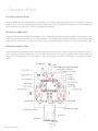
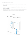
Operating & Maintenance Manual
Automatic Medical Gas Manifold
Dome Loaded Regulator NFPA v1.1
w w w . a m i c o . c o m
Contents
2
User Responsibility
4
Introduction
Features
5
5
Description of the Manifold
Shipment Details
The Manifold Enclosure
Header Bar Wall Support Bracket
Manifold Display Board
6
6
6
6
6
Description of Parts
Main Line Source Valve
Bank Regulator
Pressure Transducers
Check Valve
Line Regulator Ball Valve
Dual Line Regulator
Pressure Relief Valve
Pilot Regulator
Solenoid Valve
Front Panel Indicators
Power Supply
Control Board
Gas Service Identification
Header Bar Connections
Operating Alarm System
7 - 10
7
7
7
7
8
8
8
8
8
9
9
9
10
10
10
Display Functions
11
Installation
12
Wall Mounting Instructions
13 - 15
Cylinder Bank Installation Instructions
16
Testing for Leakage
17 - 18
Amico Pipeline
Initial Power-Up
19 - 20
Gas Flow Through the Manifold
21
Manifold Switch Over
22
Performance Verification
23 - 24
Bank Regulator Pressure Adjustment
25
Bank Regulator Replacement
26
Line Regulator Pressure Adjustment
26
Line Regulator Replacement
27
Control Board Replacement
28
Cylinder Changing Procedures
29
Ordering Information
Control Cabinet Part List
30 - 31
Appendix A
Manifold Internal Layout
32
Appendix B
Piping Schematic Diagram
33
Appendix C
Wiring Schematic Heater Units
34
Appendix D
Electrical Wiring Diagram
35
Appendix E
Control Cabinet Wiring Diagram
36
Appendix F
Staggered Header Bar
37
Appendix G
Straight Header Bar Setup
38
Appendix H
Optional Header Bar Setup
39
Appendix I
Standard Manifold Flow Rates
40
Warranty
41
Notes
42 - 43
www.amico.com
3
User Responsibility
The information contained in this Installation and Maintenance Manual, pertains only to the Amico Automatic Gas
Manifold. This product will perform in conformity with the descriptions contained in this manual when assembled,
operated, maintained and serviced in accordance with the installation instructions provided.
The manifold MUST be checked periodically. Parts that are broken, missing, worn, distorted or contaminated, must
be replaced immediately. Should such repair or replacement become necessary, please contact Amico Corporation or
their distributors.
For installing CO2 and N2O manifolds outdoors, please refer to NFPA 99C “Central supply systems for nitrous oxide and
carbon dioxide shall be prevented from reaching temperatures lower than the recommendations of the central supply
system’s manufacturer, but shall never be lower than -7°C (20°F) or greater than 54°C (130°F).”
All Manifolds should not be repaired or altered without prior written approval by Amico Corporation or it’s distributors. Failure to comply will void all warranty on the manifold.
Statements in this manual preceded by the words WARNING, CAUTION, DANGER and NOTE are of special significance.
Please read these sections carefully.
4
Amico Pipeline
WARNING:
denotes steps which can prevent injury.
CAUTION:
denotes steps which can prevent damage
to equipment.
DANGER:
denotes steps which can prevent electrical
shock to equipment or to prevent serious
injury and/or death.
Introduction
The Amico Automatic Gas Manifold is a one of its kind designed to provide a reliable, uninterrupted supply of gas to
a hospital or other medical facility. The manifold utilizes multiple high-pressure cylinders divided into two equal banks.
One bank is designated as a “Primary” source of gas while other the bank stands in reserve as a “Secondary” source.
A display of LED’s on the front of the manifold indicates the status of the gas supply. Each bank has a green (IN USE),
yellow (READY) and red (EMPTY) LED. When the primary bank of cylinders is depleted, the manifold will automatically
switch to the secondary bank of cylinders without interruption of gas flow to the facility. The red LED will illuminate
when a bank is depleted and two normally closed dry contacts for the reserve In-use alarm will open. One or both sets
of contacts may be wired to an external alarm, remote buzzer and or a building management system.
When replacement cylinders are attached to the depleted bank, the red LED goes out and the yellow LED illuminates
indicating that the bank has been automatically designated as the secondary supply. No other user interaction is
required. Both sets of dry contacts close to cancel any external alarm condition.
The power supply is connected to the top right hand corner of the manifold. Connections from the manifold to Amico
master alarm must be made from terminals marked C/Signal, to the appropriate terminals (Reserve In-use) on the master Alarm or a remote buzzer.
The enclosure for the manifold is NEMA-1 (general purpose applications only) and it is not recommended to be mounted
outdoors.
The manifold has a removable front cabinet. The pre-assembled circuit board is mounted directly to the back plate of
the manifold. This design will reduce installation time and eliminate the risk of improper installation, since each of the
components of the manifold are connected and tested at the factory.
The Amico Automatic Gas Manifold is designed in accordance with the National Fire Protection Association (NFPA 99)
FEATURES INCLUDE:
•
Input power to the manifold is 110- 240 VAC, 50-60Hz
•
Incorporates six LED’s display - readable in poor lighting conditions
•
Dual line Pressure regulators.
•
Single vent access from line & operating relief valve
•
Wall mounting bracket attached to manifold for easy installation
•
Manifold complies with NFPA 99
www.amico.com
5
Description of the Manifold
SHIPMENT DETAILS
The Manifold system may be shipped in more than one carton, depending on the number of cylinder connections. The
main carton contains the following items:
•
•
•
•
Manifold control panel (with power supply assembly)
Wall mounting bracket (attached to manifold control panel)
3/4” Source shut-off valve
Installation, Operation and Service Manual
Additional cartons may contain appropriate number of headers and cylinder pigtail assemblies. As standard, header
assemblies are configured so, cylinder inlets are on 11 inch centers. Cylinders may be placed in a double row “staggered” or
single row “Straight” configuration. Cylinder inlets closest to the manifold control panel are intended for cylinders
placed directly beneath the manifold control panel. Pigtails for gases other than oxygen and helium are 36” stainless-steel flexible type. Oxygen and helium pigtails are rigid copper and are pre-bent to approximate shape for connection
to the cylinders. The manifold is designed to be mounted directly to a wall.
THE MANIFOLD ENCLOSURE
The manifold enclosure contains a switch mode power supply that can handle voltage from 110-240 vac with a built-in
fuse and terminal block. The enclosure on this manifold is NEMA-1 (general purpose applications only). This cabinet
must not be mounted outdoors.
The manifold also has a latched door that is easy to remove. The pre-assembled circuit board is located on the center of
the enclosure with a hinge mounting bracket. This design will reduce installation time and eliminate the risk of improper
installation, since all the components of the manifold are connected and tested at the factory.
HEADER BAR WALL SUPPORT BRACKET
The manifold can support, at maximum, a 5x5 staggered header bar. While
the straight header bar contains a wall support bracket on every second pipe
in between each cylinder, a standard staggered header bar has a wall support
bracket in place after every 5 cylinders, unless additional support is requested.
MANIFOLD DISPLAY BOARD
The LED’s on the front of the Manifold indicate that status of the gas supply. The primary bank will indicate (In-Use, with
the green LED turned on) and the reserve / secondary indicating (Ready, with the yellow LED turned on) or (Empty, red
LED turned on) depending on the status of gas. When the primary bank of cylinders is depleted, the manifold will
automatically switch to the secondary bank of cylinders without interruption of gas flow to the facility. The red LED will
illuminate when a bank is depleted and two normally closed dry contacts will open. One or both sets of contacts may
be wired to an external alarm, remote buzzer and or a building management system.
6
Amico Pipeline
Description of Parts
When replacement cylinders are attached to the depleted bank, the red LED goes out and the yellow LED illuminates
indicating that the bank has been automatically designated as the secondary supply. No other user interaction is
required. Both sets of dry contacts close to cancel any external alarm condition.
MAIN LINE SOURCE VALVE
An isolation valve ¾ “ with a locking handle supplied with the
manifold, should be installed on top of the manifold connecting
to the main supply line.
BANK REGULATOR
A dome loaded, single stage, diaphragm type regulator. Used
to reduce incoming cylinder contents pressure to a lower
intermediate pressure. Bank regulator (one for each bank of
cylinders) has an internal adjusting spring used to set a “base”
pressure of approximately 100 PSI (200 PSI on Nitrogen manifolds).
“Dome” (i.e. bonnet or bell) of regulator is a pressure tight
chamber. When pressure is applied to the dome, the amount
of force applied is added to the force of the adjusting spring.
For example, when 55 PSI of pressure is applied to the dome, the
100 PSI base pressure setting is raised to approximately 155 PSI.
PRESSURE TRANSDUCERS
Senses the bank pressure and transfers information to the display
board to indicate the In-use, Reserve & Empty mode. There are
two transducers in the manifold cabinet, one for the left bank
cylinder and one for the right bank cylinder.
CHECK VALVE
Check valve is provided upstream of each bank regulator to
prevent back flow while servicing a bank regulator.
www.amico.com
7
Description of Parts
LINE REGULATOR BALL VALVE
Quarter-turn ball valves are provided upstream and downstream of each line
regulator. These valves allow for removal and servicing of one line the regulator while the other is in use. All four ball valves are normally in the open
position.
DUAL LINE REGULATOR
On every Amico Automatic Gas Manifold the line regulator is capable of maintaining a constant dynamic delivery of pressure at the maximum designed
flow rate of the system. For Oxygen, Nitrous Oxide, Medical Air and Carbon
Dioxide service, the line regulators are factory preset @ 55psi and for Nitrogen its 170psi.
PRESSURE RELIEF VALVE
Pressure relief valves are installed downstream of all pressure regulators and
are set at no more than 50% above the setting of the pressure regulator.
Relief valves are capable of fully relieving the pressure at the set point. All
pressure relief valves in the manifold have piping connections to allow for connection of a vent line to the outside of the facility.
PILOT REGULATOR
A single stage, diaphragm type, relieving regulator used to limit the amount
of pressure provided to the domes of the bank regulator. Used only on Nitrogen manifolds and manifolds with 100 PSI delivery pressure.
SOLENOID VALVE
A 12 VDC, solenoid assembly used to direct dome bias pressure to one of the
bank regulators. As dome bias pressure is directed to one of the bank regulators, dome pressure of the other bank regulator is vented through an exhaust
in the solenoid valve.
8
Amico Pipeline
Description of Parts
FRONT PANEL INDICATORS
Six front panel indicators monitor the status of the manifold.
POWER SUPPLY
The power supply is a 120 - 240 VAC, 50-60hz, which is
mounted on the top right hand side of the manifold and is
provided with a 1 amp fuse.
CONTROL BOARD
An electronic circuit board that controls the bank switch over.
It monitors the pressure with the help of the bank transducers
and controls the solenoid valve in order to initiate the bank
switch or changeover. The control board illuminates the appropriate front panel indicators and also provides dry contacts
for the activation of a remote buzzer or external master alarm.
Power to the control board is provided by the external power
supply.
DANGER: Electrical shock hazard. Ensure that the
main power source is turned off during the connection
of the power supply.
www.amico.com
9
Description of Parts
GAS SERVICE IDENTIFICATION
Amico manifolds are clearly labeled for the intended gas use, indicating the appropriate gas that is attached on the cabinet door. There two pipes extending from the top of the cabinet, one is for the main line pressure and the other is the
vent for the pressure relief valves, which is also labeled accordingly.
HEADER BAR CONNECTIONS
The gas specific header bar should be attached to the In-let block on either side of the manifold. The In-let block is provided with a sintered bronze filter and a “C” clip to secure it. The header should contain the proper gas connections and
all cylinder bar connections, as well as the pigtail (hose) assemblies should comply with CGA standard B96, “ComOPERATING ALARM SYSTEMS
The manifold control cabinet contains the required circuitry to send a dry contact signal to the alarm unit when a
bank is empty and change-over occurs. The normally closed internal circuitry is designed to alarm when there is an
open circuit. The depletion of a bank triggers a relay, which renders the alarm circuit open and initiates the alarm
signal.
10
Amico Pipeline
Display Functions
1. Introduce power to the control cabinet.
2. Follow Cylinder Changing Procedures on the side of the cabinet to ensure that all cylinders, fittings are secure and
properly connected to the Header bar.
3. Check the indicator LED for proper functioning.
4. Only one Green LED, on the side which had its operating regulator set first, should be lit and the other side should
have an Yellow LED lit.
5. Close the cylinder valve on the primary bank and watch the indicator LED to ensure proper functioning. The primary
bank pressure should fall, while the secondary and line pressures stays constant.
6. When the primary pressure falls to approximately 120psi for all gases except Nitrogen 220psi the bank switch
over occurs, the line pressure will remain constant with the LED display indicating the bank In-use.
7. With the Amico Automatic Gas Manifold wired up to the Amico Master Alarm, the changeover from primary to secondary supply will cause an audible alarm buzzer and the appropriate indicator LED on the Master Alarm will illuminate.
This can also be achieved by using the switch over test button located on the back of the control board.
www.amico.com
11
Installation
PRECAUTIONS
•
Tampering with gas specific connections shall be prohibited. Do not alter, remove or modify gas specific connections.
•
Keep all manifold parts, tools and work surfaces free of oil, grease and dirt. These and other flammable materials
may ignite when exposed to high pressure oxygen or nitrous oxide.
•
Do not use chemicals, lubricants or sealants unless specified in these instructions.
•
Before connecting cylinder to manifold, momentarily open and close cylinder valve to blow out dirt and debris.
•
After connecting cylinder to manifold, open cylinder valve S-L-O-W-L-Y to allow heat of compression to dissipate.
•
Do not use flame or “sniff ” tests for leaks.
•
Do not apply heat to any part of the manifold system.
•
Always secure high-pressure cylinders with racks, straps, or chains. Unrestrained cylinders may fall over and
damage or break off cylinder valve.
•
Do not repeatedly bend, sharply bend, or twist copper pigtails as damage to tubing may occur.
•
After the manifold wall bracket has been mounted, one person alone should not attempt to lift and hang
the manifold cabinet.
•
Do not put the manifold into operation until verified by a qualified person as per NFPA 99 or other local
standards.
12
Amico Pipeline
Wall Mounting Instructions
1.
Remove manifold control panel from the shipping carton and ensure it is in upright position on the foam
packaging insert.
2.
Using the back support bracket as a template, place on the flat wall, align top of the bracket with the level
horizontal line. The vertical center line of the bracket will be the vertical center line of the installed manifold. The
support bracket should be mounted 61 1/2” [1,562.1 mm] from the finished floor to the bottom hole on the
bracket as shown in figure 1).
3.
Mark locations of mounting holes. Remove the bracket and drill mounting holes. Attach the bracket to the wall
with appropriate anchors (supplied by others). 3/8” [9.525 mm] diameter anchors are recommended.
Figure 1
Locate bracket per
horizontal line
Mark Location
of holes
61 1/2”
[1,562.1mm]
To Floor
www.amico.com
13
Wall Mounting Instructions
4.
Hang the manifold control panel on the mounting bracket. The top two control panel mounting bolts will slide
into slots of the bracket. The bottom of the manifold control panel should be angled away from the bracket until
the top two bolts have been inserted as shown in figure 2.
Figure 2
NOTE:
A bracket mounting height of 61 1/2” [1,562.1 mm] from the finished floor to the bottom hole on the support bracket
allows for adequate clearance beneath the manifold when utilizing standard “H” size or slightly taller cylinders.
14
Amico Pipeline
Wall Mounting Instructions
The bottom of the control panel can then be positioned, so that the holes at the bottom of the panel align with the holes
in the hanging bracket. Use 3/8” [9.525 mm] bolts to secure the cabinet to the bracket as shown in Figure 3.
Figure 3
WARNING: Do not attempt to lift manifold alone. Two people are
recommended in order to hang manifold onto wall mounting bracket
CAUTION: Do not use thread sealant on header or pigtail connections.
CAUTION: Each header segment must be supported by a header
bracket before additional header segment are added.
www.amico.com
15
Cylinder Bank Installation Instructions
CAUTION: This section contains important information necessary for proper installation of the
cylinder banks. Read it carefully before installing cylinder banks.
•
Position the wall brackets, if required, to support the Header bars and bolt in place.
•
Connect the two high pressure inlet valve / header bar assemblies to the inlet blocks on either side of the cabinet.
•
Secure the Header bar assembly by tightening the union nuts onto the In-let blocks. The manifold can support
a maximum 5 x 5 staggered header bar. While the straight header bar contains a wall support bracket on every
second pipe in between each cylinder, for the staggered a support bracket is installed after every 4 – 5
cylinders, unless additional support is required.
•
Remove the plug and chain assembly on each of the outlet connections on the cylinder extension bar. Attach
the cylinder pigtails to the header bar connections, while ensuring the check valves are operating in the proper
direction.
WARNING: To avoid contamination with particles or other potential hazardous materials, keep
pigtails in plastic wrapping until such time as connection to gas cylinder is planned.
When the medical gas piping system has been tested in accordance with NFPA 99, the manifold can then be connected
to it.
The outlet pipes leading from the Amico control cabinet should be connected to their respective pipeline system
connections. The connection to the relief valves should be made with a union (supplied by others) to facilitate
change, if required.
An appropriate sealing compound that is suitable for the gas being transmitted shall be used for threaded connections.
WARNING: If downstream joints near the cabinet outlet are to be silver brazed, special attention
must be given not to overheat the copper tubing, since this may alter the sealing compound
used in the threaded joints leading from the control cabinet.
16
Amico Pipeline
Testing for Leakage
The following instructions apply for performing a leak test on the joints made during assembly and connection of the
Amico manifold.
The connections inside the Amico control cabinet have been inspected at the manufacturing plant and DO NOT require
leak testing. In order to determine whether any leaks exist between cylinder Header bar sections or at the pipeline
connections, the systems must be pressurized using either oil-free dry air or oil-free dry nitrogen.
In the case of medical Oxygen, Nitrous Oxide, or Carbon Dioxide Amico manifolds, the actual services gases ARE NOT
suitable for leak testing due to their inherent dangerous properties. Leak testing must be performed using either oil-free
dry air of oil-free dry nitrogen. In the case of either Medical Air or a Nitrogen Amico manifold, the actual service gas may
be used to perform the leak tests as follows:
•
Connect a cylinder of the manifold service gas to each side of the header bar using the proper cylinder connection
hose assemblies (pigtails) supplied.
•
Make sure all other outlets are capped with the plug and chain assemblies supplied.
•
Make sure that the high pressure inlet valves of each bank are fully OPEN.
•
“Slowly” open the two cylinder valves on each side of the cabinet, one at a time, to pressurize the header bar
and pipeline.
•
All outlets from the pipeline, downstream of the manifold, should be closed and thus there should be no flow
from the manifold.
•
Check for leaks at all cylinder extensions joints and at the joints where the pipes are connected to the pipeline,
using a commercial leak detector, which is compatible with oxygen.
•
If any leaks are found, the system must be depressurized by bleeding through a convenient pipeline outlet and
the faulty connections must be repaired.
•
The Header bar connections may be tightened one more turn, maintaining the horizontal location of the
cylinder adapters or a further application of an oxygen service threaded sealant may be required.
•
If the brazed pipeline connections leak, they must be removed, cleaned and then re-brazed following the
proper technique. All repaired joints must be pressure tested as previously.
www.amico.com
17
Testing for Leakage
Precautions
The Amico Automatic Gas Manifold`s are designed in accordance with the current revision of NFPA 99.
There are three categories of the Amico manifolds depending upon the delivery pressure. The following gas types are
available for each delivery pressure:
55 PSI Delivery Pressure
•
Oxygen, Nitrous Oxide, Medical Air, Carbon Dioxide, Helium, Argon
100 PSI Delivery Pressure
•
Oxygen, Medical Air, Carbon Dioxide
170 PSI Delivery Pressure
•
Nitrogen, Instrument Air
Delivery (Line) Pressure - (see NOTE above)
Delivery (Line) Pressure
Intermediate Pressure - Ready Bank
Dome Bias Pressure
Intermediate Pressure - In Use Bank
Intermediate Relief Valve
Line Regulator Relief Valve
Maximum Inlet Pressure
55 PSI
100 PSI
55 PSI **
150 ± 10 PSI*
350 PSI
75 PSI
3000 PSI
100 PSI
200 PSI
50 PSI
250 ± 10 PSI
350 PSI
150 PSI
3000 PSI
170 PSI
200 PSI
50 PSI
250 ± 10 PSI
350 PSI
225 PSI
3000 PSI
* The intermediate pressure valve of the “In Use” bank is dependent upon the dome bias pressure. Variations from the 55
PSI delivery pressure will affect the intermediate pressure reading.
** Same as delivery pressure.
18
Amico Pipeline
Initial Power-Up
1.
Release the two latches on either side of the manifold control panel and remove the cover.
2.
Verify the following:
• Both master valves located on both header bars are turned fully counter clockwise (open).
• All four line regulator isolation valves are open (handles horizontal).
• Power supply has been connected.
• Both red “empty” indicators on the front of the manifold are illuminated.
• If connected to a master alarm panel, “Secondary Supply” alarm is activated.
3.
Close 3/4” source shut-off valve.
4.
Slowly open one cylinder on the right side of the manifold
5.
Verify the following:
• Right bank red “empty” LED goes out.
• Right bank green “in use” LED illuminates.
• Right bank cylinder contents gauge reads cylinder pressure.
6.
Slowly open one cylinder on the left side of the manifold.
7.
Verify the following:
• Left bank red “empty” LED goes out.
• Left bank yellow “ready” LED illuminates.
• Left bank cylinder contents gauge reads cylinder pressure.
• If connected to a master alarm panel, “secondary supply” alarm is not activated.
8.
Close right bank cylinder. Slightly depress bleed valve located on the side of the regulator. Verify the
following:
• Right bank cylinder contents gauge drops slowly.
• As the right cylinder contents gauge is nearly depleted, the manifold changes over to the left bank.
• After change-over, the right bank green “In Use” LED goes out and the red “Empty” LED illuminates.
• After change-over, the left bank yellow “Ready” LED goes out and the green “In Use” LED illuminates.
9.
Verify the “line pressure” gauge reading is acceptable.
10.
Slowly open one cylinder on the right side of the manifold
www.amico.com
19
Initial Power-Up
11.
Verify the following:
• Right bank red “empty” LED goes out.
• Right bank yellow “ready” LED illuminates.
• Right bank cylinder contents gauge reads cylinder pressure.
12.
Close left bank cylinder. Depress valve located on the side of the line regulator. Verify the following:
• Left bank cylinder contents gauge drops slowly.
• As left cylinder contents gauge is nearly depleted, the manifold change over to the right bank.
• After change-over, the left bank green “in use” LED goes out and red “empty” LED illuminates.
• After change-over, the right bank yellow “ready” LED goes out and green “in use” LED illuminates.
13.
Slowly open one cylinder on the left side of the manifold.
14.
Verify the following:
• Left bank red “empty” LED goes out.
• Left bank yellow “ready” LED illuminates.
• Left bank cylinder contents gauge reads cylinder pressure.
• If connected to a master alarm panel, “secondary supply” alarm is not activated.
15.
Close left and right side cylinders.
16.
Record pressure readings of left and right bank cylinder contents gauges.
17.
Wait 15 minutes.
18.
Compare current readings of the left and right bank cylinder contents gauges to those recorded in step 16. If
there is a noticeable pressure change on either gauge, perform leak testing described in Leak Testing.
19.
Reinstall manifold control panel cover.
20.
Slowly open all cylinder’s on both banks of the manifold.
21.
Open 3/4” source shut-off valve.
20
Amico Pipeline
Gas Flow Through the Manifold
High pressure gas is provided to the left and right manifold bank inlets via cylinders, pigtails, and header assemblies.
Flow of high pressure gas through the left and right side of manifold is exactly the same, each passing through a master
valve located on the header and then directly to a bank regulator.
Bank regulators reduce incoming cylinder pressures to an intermediate pressure. Bank regulators are referred to as a
“dome loaded” type of regulator. These regulators have an internal adjusting spring manually set at a specific pressure
similar to other diaphragm type pressure regulators. In addition to internal adjusting spring, bias pressure may be
applied to the dome of the regulator (adjusting spring side of diaphragm) thus boosting pressure above what is manually set by the adjusting spring. This output pressure boost will be approximately equal to the amount of bias pressure.
For example, if a bank regulator is manually adjusted to 100psi via internal adjusting spring, and a dome bias pressure
of 55psi is applied, the output pressure will increase to approximately 155psi (100 + 55). When the bias pressure is removed, the output pressure setting will return to 100psi.
Outputs of both the left and right bank regulators pass through check valves and connect together upstream of the
dual line regulator assembly. An intermediate relief valve protects components between the bank and line regulators in
the event of a bank regulator seat failure.
The dual line regulator assembly consists of two line regulators plumbed in parallel with upstream and downstream
isolation 1/4” turn ball valves. Output of both the line regulators tee together and exit at the manifold’s main outlet. A
line relief valve along with a line pressure gauge is connected to the manifold’s main outlet.
Outlet pressure is then routed to a dome regulator reducing pressure to 55 PSI at the solenoid switch. Solenoid switches
55psi (dome bias pressure) to one of the bank regulators. When one bank regulator is supplied bias pressure, the other
bank’s dome regulator’s is vented to the atmosphere. An electronic circuit board controls the solenoid valve based
upon the input received from the right and left pressure transducer. The solenoid valve directs bias pressure to the bank
designated as primary.
Manifolds designed for 55psi nominal output pressure do not incorporate a Pilot regulator. Full line pressure (55psi) is
routed directly to the solenoid valve which is used as dome bias pressure.
www.amico.com
21
Manifold Switch Over
After electrical power has been applied to the manifold, the side pressurized first is designated primary or “In Use” bank.
In order to simplify the following explanation, we will arbitrarily select right side of manifold as primary bank. The green
“In Use” LED on the right side will be illuminated and the yellow “Ready” LED on the left (secondary) bank will be illuminated.
The Solenoid valve directs dome bias pressure to the bank regulator on the right side. If we use a 55psi oxygen manifold
as an example, the output of the right bank pressure regulator is approximately 155psi (100psi base pressure + 55psi
bias pressure).The output of the left bank regulator is a approximately 100psi (base pressure only, no bias pressure).
Since the bank regulator on right side has the highest pressure, all flow is supplied by right bank of cylinders.
As the cylinder pressure on the right side depletes, the pressure transducer on that side signals to the circuit board to
switch the solenoid valve. The solenoid valve then vents the dome bias pressure from the right bank regulator and directs the bias pressure to the left bank regulator. The Green LED “In-use” on the right side goes out and the Red “empty” LED
illuminates, indicating a Reserve In-use alarm with the Yellow LED on left going off and the Green LED being illuminated.
When cylinders on the right side are replaced and pressure is restored, the right pressure transducer sends a signal to
the circuit board, which in turn cancels the remote switch over alarm and the Red” Empty” LED turns off and the Yellow
“ Ready” LED gets illuminated.
Since the left bank regulator has the dome bias pressure applied, its output pressure is boosted to approximately 155psi.
The right bank regulator has no dome bias pressure and its output pressure is controlled only by base pressure (100 PSI).
All flow is supplied by the left bank of cylinders until the pressure drops to approximately 120psi, the pressure transducer
sends a signal to the circuit board, causing a switch over to the right side in same fashion as previously described.
NOTE:
In the event of a power fluctuation or failure, a switch over alarm will be activated on the master alarm panels.
•
The solenoid valve will direct dome bias pressure to the left tank, which is the default side, if the right side is in-use.
•
If the left side is in-use, the solenoid valve will continue to direct dome bias pressure until the bank depletes before
the right side takes over.
•
The solenoid will not prevent the flow from being supplied no matter which side is in-use and until the system is
completely out of gas.
22
Amico Pipeline
Performance Verification
Use following test steps to verify the manifold’s functional performance:
1.
Remove manifold cover.
2.
Before beginning the test, verify following:
3.
If the manifold is not in use, close the 3/4” source shut-off valve.
4.
Verify that the two right-side line regulator isolation valves are open and the two left-side line regulator isolation
valves are closed.
5.
As a starting point for this procedure, set the manifold, so right bank is in use. If the right bank green LED is illuminated, proceed to the next step. If the left bank green LED is illuminated, manually switch the manifold to the
right side by pressing the left switch on control board.
6.
Verify that the right bank green LED “IN USE” and the left bank yellow “READY” lights are illuminated.
7.
If the manifold is connected to a master alarm panel, verify the manifold switchover alarm is not activated.
8.
If the manifold is equipped with a pilot regulator, verify the gauge on it reads 50 PSI.
9.
Verify gauge reading for the “In-use” right bank regulator. If the pressure is not correct, refer to the bank regulator
pressure adjustment procedure.
10.
Verify the line pressure gauge reading, If the pressure is not correct, refer to the line regulator pressure adjustment procedure. Note the reading for later use.
11.
Watch the pressure gauge readings of the right side bank regulator and the line pressure gauge for at least five
minutes. Readings may be slightly higher without vent flow but verify the readings do not continue to increase.
12.
Close all cylinders on the right side of the manifold. Use the bleed valve on the line regulator to slowly vent off
pressure until the right bank high pressure gauge drops. Verify the manifold, switches to left bank when the right
bank high pressure gauge drops below the specified setting of the bank regulator.
13.
Verify only the left bank Green LED “In-use” and the right bank Red “Empty” LED illuminates.
14.
If the manifold is connected to a master alarm panel, verify that the switchover alarm is activated.
15.
Close the right-side line regulator ball valves and open the left line regulator ball valves.
16.
Slightly depress the bleed valve on the left line regulator to create a small flow of gas through manifold.
17.
Verify the pressure gauge reading on the bank “In-use” regulator to see if it is set up as per the specified pressure
setting. If the pressure is not correct, refer to the bank regulator pressure adjustment procedure.
www.amico.com
23
Performance Verification
18.
Verify that the line pressure gauge reading is same as in step 11. If the pressure is not correct, refer to the Line
regulator pressure adjustment procedure.
19.
Watch the pressure gauge readings on the left bank regulator and the supply line for at least five minutes to ensure the readings do not continue to increase.
20.
Close all cylinders on the left side of the manifold. Depress the bleed valve slightly so that the left bank high pressure gauge drops slowly. Verify that the manifold switches to the right bank when the left bank high pressure
gauge drops below the specified setting of the bank regulator.
21.
Verify only the right bank Green “In-use” LED and the left bank Red “Empty” illuminates.
22.
Slowly open a cylinder on left side. Verify that the left bank Red “Empty” LED goes out and the left bank Yellow
23.
“Ready” LED illuminates.
24.
Open both the right side line regulator ball valves.
25.
Close the left and right side cylinders.
26.
Record the pressure readings of the left and right bank cylinder content gauges.
27.
Verify after 15 minutes, the pressure reading on the gauges should remain the same.
28.
Slowly open all cylinders on both banks of the manifold.
29.
Using the switches on the circuit board, switch the manifold to the bank of cylinders with the least pressure.
Reinstall the manifold control panel cover.
30.
24
Open the 3/4” source (line) shut-off valve.
Amico Pipeline
Bank Regulator Pressure Adjustment
This procedure should only be performed if the bank regulator pressures are not within acceptable limits during performance verification procedure or after installation of a new bank pressure regulator.
Base pressure setting is a mechanical adjustment controlled by the regulator’s internal adjusting spring and without
any dome bias pressure. Recommended settings are listed on page 18 in the Table under the heading of “Intermediate
Pressure - Ready Bank”. After the base pressure has been set, the pressure will be increased by the amount of dome bias
pressure applied.
1.
Shut off all cylinders on both banks of the manifold.
2.
Close the main supply source valve.
3.
Using the control board switches, cycle the manifold from bank to bank to vent residual dome bias pressure.
4.
Remove nylon tube then using a 9/16” wrench, remove pipe (quick connect) adaptor from the dome of bank
5.
regulator(s) to be adjusted.
6.
Depress bleed valves on both line regulators to relieve all pressure from the manifold.
7.
Slowly open one cylinder on the side of manifold that needs adjustment. For example, if the right bank regulator needs adjustment, open one cylinder on the right side of manifold.
8.
Slightly vent off the pressure from the bleed valve to create a small flow of gas through the manifold.
Using a 7/32” Allen wrench through the hole of the dome / bell, set the bank regulator to the specified setting.
(Intermediate Pressure - Ready Bank).
9.
Close cylinder valves.
10. If the other bank regulator also needs to be adjusted, repeat steps 6 through 10.
11. Apply Teflon tape, reinstall the pipe (quick connect) adaptor on dome of bank regulator and reinstall nylon
tube.
12. Slowly open all cylinders on both manifold banks.
13. Open main supply source valve.
www.amico.com
25
Bank Regulator Replacement
Should it be necessary to replace the bank regulator, it can be done while the manifold is in service. However, this should
only be done by qualified technicians experienced in servicing medical equipment.
1. Remove two top screws at the base of the display board bracket and bend the display board assembly back for
easy access to the union nuts that secures the bank regulator. (Follow label instructions)
2. Close all cylinders on the side of the manifold where the bank regulator is to be replaced.
3. Ensure that the service bank is the reserve / secondary, if not cycle the manifold from In-use to reserve by using the
circuit board control switch to vent residual dome bias pressure.
4. Slowly break the 1 1/8” union(s) allowing gas to slowly vent out from both the inlet and outlet side of the bank
regulator.
5. Remove nylon tube from regulator dome.
6. Install new regulator bank regulator. (May require slight adjustment to the fittings on the regulator to align with
the secure fittings on the manifold).
7. Tighten union nut on the inlet and outlet of the new bank regulator.
8. Reinstall nylon tube.
9. Close display board assembly and attach bracket with the 2 screws.
10. Slowly open cylinders and set bank regulator’s output pressure as described in Bank Regulator Pressure Adjustment
procedure.
Line Regulator Pressure Adjustment
This procedure should be performed if the line regulator pressure are not within acceptable limits during performance
verification procedure or after installation of a new line regulator.
1.
With both the bank regulators supplying pressure, open only one ball valve on the inlet and outlet of the line regulator to be adjusted.
2. Slightly open/depress the bleed valve on the side of the regulator to create a small flow of gas though the manifold.
3. Using the handle on the bonnet of the regulator, turn to adjust the pressure to the specified setting, as mentioned
on the cabinet door by observing the line gauge.
4. Repeat (steps 1-3) to adjust the other line regulator.
5. After adjusting the pressure to the specified setting open all balls valves and ensure the supply line remains open.
26
Amico Pipeline
Line Regulator Replacement
If necessary, the line regulator replacement can be performed while manifold is in service. However, this should only
be done by qualified technicians experienced in servicing medical equipment.
1. Close the two ball valves on inlet and outlet of line regulator to be replaced.
2. Loosen union nuts on two closed isolation valves.
3. Vent pressure from the bank, which was shut off in step 2 by depressing the bleed valve on side of the regulator.
4. Ensure the orientation of fittings (direction of gas flow) is the same on the replacement regulator. Install fittings on
new regulator.
5. Inspect O-ring removed from the ball valve union. If damaged, replace O-ring.
6. Verify the correct orientation of fittings on the regulator, some slight adjustment may be required to align with
the ball valves without causing stress to the fittings.
7. Hand-tighten the two ball valve union nuts and then with a wrench snug lightly to ensure the fittings are secure.
NOTE : do not over tighten unions, as it is an o-ring seal.
8. Open the ball valves and set line regulator’s output pressure as described in Line Regulator Pressure Adjustment
procedure.
www.amico.com
27
Control Board Replacement
If necessary, the control board replacement can be performed while the manifold is in service. However, this should only
be done by qualified technicians experienced in servicing medical equipment.
1. Remove two top screws at the base of the display board bracket and bend the display board assembly back.
2. Disconnect power supply.
3. Remove the screws located on the circuit board, which detaches it from the front plate. Note orientation of the
old circuit board and remove the wiring, one at a time and connect each wire to the appropriate terminal on
the new board.
4. Install the circuit board and fasten the screws to secure it, turn bracket up and then fasten the two screw at the
base.
5. Reconnect power supply to the manifold cabinet.
6. Check the correct operation of the circuit board by simulating a bank switch over a couple of times.
28
Amico Pipeline
Cylinder Changing Procedures
1. Keep the main bank valve open throughout these procedures.
2. Close cylinder valves on all empty cylinders.
3. Disconnect pigtails from cylinder valve outlets, using an appropriate wrench.
4. Place protective caps over the cylinder valves of the empty cylinders and move them aside.
5. Remove protective caps of the full cylinders. Visually inspect the cylinder valves for dust, grease or oil.
6. Using a clean (lint free) cloth, wipe each cylinder valve outlet clean. Do not use your fingers.
7. Standing to one side, “crack” the cylinder valve by briefly opening and closing them to blow out any dust. Make
sure they are pointing away from you and other personnel.
8. Connect the pigtails to the cylinder valve outlets and tighten the nut with an appropriate wrench.
9. Very S-L-O-W-L-Y open the cylinder valve on the cylinder closest to the control cabinet. Watch the bank pressure
display on the front of the cabinet, to make sure the pressure rises slowly to the full cylinder pressure reading.
Wait one full minute.
10. Proceed to S-L-O-W-L-Y open the remaining cylinder valves one at a time.
WARNING: High pressure oxygen systems must be handled with CAUTION. Spontaneous combustion
may occur if oxygen came into contact with grease or oil. Ensure that hands, gloves, clothing and tools
are kept clean and free of oil and grease. Be careful not to introduce dust or other contaminants into the
system when changing cylinders. Failure to comply with the procedure may be hazardous.
WARNING: Fire Hazard. DO NOT permit smoking, or any other source of ignition in area where the
manifold is located, or near the relief valve vent outlet. Be certain that all connections are free of dirt,
grease, and oil. These substances burn with great intensity in air, enriched with oxygen, or nitrous
oxide and some gas mixtures.
www.amico.com
29
Ordering Information
DL = Dome Loaded (NFPA)
Manifold Cabinet:
M3D-DL-HH-U-GAS
The Word “GAS” Defines the Type
of Gas:
A = Analog
D = Digital
U = English (NFPA)
Oxygen
Nitrogen
Medical Air
Carbon Dioxide
Nitrous Oxide
HH = High Pressure
HHH = Heaters
Header-Bar Assembly:
OXY
NIT
AIR
CO2
N2O
M2-HBYY-XXU-GAS
The Letters “YY” Defines the Type of
Header-Bar Assembly:
The Letters “XX” Defines the Number
of Cylinders:
“TS”
“TC”
“XS”
“XC”
2 x 2 use 04
4 x 4 use 08
= Straight c/w Stainless Pigtails
= Straight c/w Copper Pigtails
= Staggard c/w Stainless Pigtails
= Staggard c/w Copper Pigtails
Wall Bracket for Header-bar Assembly:
M-X-HB-WLBRKIT
CONTROL CABINET PARTS LIST
DESCRIPTION
MODEL NUMBER
Pressure transducer for Oxy, N2O, Air, CO2, & Nit
M2-X-MAN-07B
Line pressure regulator for Heavy Duty Manifolds
M2-X-MAN-42E-L
M2-X-MAN-42E-R
M2-X-MAN-42E-LN
M2-X-MAN-42E-RN
M3-X-MAN-18DL-L
M3-X-MAN-18DL-R
M2-REG700-RK
M2-REG250-RK-HP
For NIT
Operating pressure regulator for HD Manifolds
Repair Kit Line pressure regulator - HD
Repair Kit Operating pressure regulator
30
=
=
=
=
=
Amico Pipeline
CONTROL CABINET PARTS LIST
DESCRIPTION
Intermediate check valve for all gases
Operating pressure relief valve Nitrogen
Operating pressure relief valve Oxy, N2O, Air & CO2
Line Pressure relief valve for Nitrogen
Line pressure relief valve for Oxy, N2O, Air & CO2
Plug & Chain assembly - Air
Plug & Chain assembly - CO2
Plug & Chain assembly - N2O
Plug & Chain assembly - Nit
Plug & Chain assembly - Oxy
Copper pigtail c/w Check valve - Air
Copper pigtail c/w Check valve - CO2
Copper pigtail c/w Check valve - N2O
Copper pigtail c/w Check valve - Nit
Copper pigtail c/w Check valve - Oxy
Stainless pigtail c/w Check valve - Air
Stainless pigtail c/w Check valve - CO2
Stainless pigtail c/w Check valve - N2O
Stainless pigtail c/w Check valve - Nit
Extension wall support
High pressure inlet valve
ALERT-2.1 LED circuit board assembly
Manifold Power Supply
Solenoid Valve
MODEL NUMBER
M-X-MAN-33B
M-X-IN-72W-350
M-X-IN-72W-350
M-X-IN-72W-225
M-X-IN-72W-075
M-X-HB-NUT-AIR
M-X-HB-NUT-CO2
M-X-HB-NUT-N2O
M-X-HB-NUT-NIT
M-X-MAN-36
M-X-HB-PTC-AIR
M-X-HB-PTC-CO2
M-X-HB-PTC-N2O
M-X-HB-PTC-NIT
M-X-HB-PTC-OXY
M-X-HB-PTS-AIR
M-X-HB-PTS-CO2
M-X-HB-PTS-N2O
M-X-HB-PTS-NIT
M-X-HB-WLBRKIT
M-X-HB-HPVLV-A
M3-LED-DLCB
M2-X-POWER
M3-X-MAN-SOLVLV
www.amico.com
31
Appendix A
Manifold Internal Layout
32
Amico Pipeline
Appendix B
Piping Schematic Diagram
Item
1
2
3
4
5
6
7
8
9
TO
PIPELINE
DISTRIBUTION
SYSTEM
VENT TO
OUTSIDE
10
9
11
12
13
13
7
Description
Pig-Tail check valve
Cylinder valve
High pressure inlet valve
Pressure Transducer
Operating pressure regulator
Check valve
Line pressure regulator
2 - Way valve
Line pressure relief valve
Operating pressure relief valve
Bleed Valve
Operating pressure gauge
Pilot Regulator For Nitrogen
7
8
11
CONTROL CABINET
10
6
6
4
LEFT HAND BANK
3
CYLINDER PRESSURE
HP
LB
12
6
4
12
RIGHT HAND BANK
HP
RB
3
CYLINDER PRESSURE
1
5
LEFT
BANK
5
2
RIGHT
BANK
PIPING SCHEMATIC DIAGRAM
DUAL LINE REGULATORS (NFPA)
www.amico.com
33
Appendix C
Wiring Schematic Heater Units
Power Supply
Heater Cartridge
Wires
Heater Cartridge
(Inside Inlet Pressure Block)
Inlet Pressure
Block
Reset Switch
Reset Switch
Heater Cartridge
(Inside Inlet Pressure Block)
Inlet Pressure
Block
The Heaters normally switch on when the temperature drops below 24°C or 75°F. If the temperature exceeds 65-75°C or
160-175°F, the Heater re-set switch will trip and the heaters will automatically switch off. To re-set the Heaters, remove
the heater covers & press the red button on the re-set switch to activate. When the Heaters are in use or switched on, it
will draw up to 3 amps of current. The Heater Cartridge is 200Watts (each side), normally both sides do not switch on
together. It depends on the flow of gas or climatic conditions.
34
Amico Pipeline
Appendix D
Electrical Wiring Diagram
Amico Medical Gas Alarm
Master Alarm
115 VAC
Supply
Voltage
Amico Gas
Manifold
Connect the NO loop to the
appropriate points.
110 / 240 VAC Wiring
50 / 60 Hz
C
NO
Current Draw: 1 Amp. Max.
External Power
Supply
www.amico.com
35
Appendix E
Control Cabinet Wiring Diagram
36
Amico Pipeline
Appendix F
Staggered Header Bar
www.amico.com
37
Appendix G
Straight Header Bar Setup
38
Amico Pipeline
Appendix H
Optional Header Bar Setup
www.amico.com
39
Appendix I
Straight Header Bar Setup
40
Amico Pipeline
Pipeline Equipment
Warranty Policy
Amico Corporation warrants its Medical Gas Pipeline Equipment to be free from defects in material and workmanship
for a period of twelve (12) months from the date of shipment. Within this period Amico will repair or replace any part
on site, or at the factory, which is proven to be defective at Amico’s cost.
Furthermore, Amico will warrant its material to be free from defect for an additional period of four (4) years (five (5)
years from the date of shipment). Within this period, Amico will replace any part, at no charge, which is proven to be
defective. Shipping and Installation costs after the 1st twelve (12) months will be borne by the Customer.
This warranty is valid only when the product has been properly installed according to Amico specifications, used
in a normal manner and serviced according to factory recommendations. It does not cover failures due to damage
which occurs in shipments or failures which resulted from accidents, misuse, abuse, neglect, mishandling, alteration,
misapplication or damage that may be attributable to acts of God.
Amico shall not be liable for incidental or consequential damages resulting from the use of the equipment.
All claims for warranty must first be approved by Amico’s Service Department ([email protected] or 1-877-4626426). A valid Return Goods Authorization (RGA) number must be obtained from Amico prior to commencement of
any service work. Warranty work, which has not been pre-authorized by Amico, will not be reimbursed.
www.amico.com
41
Notes
42
Amico Pipeline
Notes
www.amico.com
43
www.amico.com
Amico Pipeline | www.amico.com
85 Fulton Way, Richmond Hill
Ontario, L4B 2N4, Canada
C
US LISTED
Toll Free Tel: 1.877.264.2697
Toll Free Fax: 1.866.440.4986
Tel:
905.764.0800
Fax: 905.764.0862
APE-INSTAL-MAINT-DL-MANI-v1.1 PRINTED FEB 12