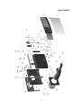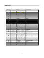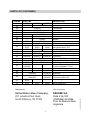
1
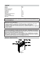
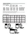
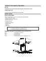
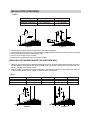
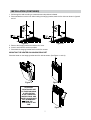
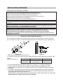
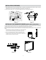
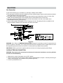
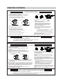
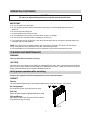
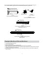
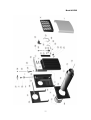
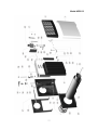
OWNER'S OPERATION AND
INSTALLATION MANUAL
FOR MODELS
GRAVITY
DIRECT VENT
WALL FURNACE
AGDV8, AGDV12, AGDV20
WARNING: If the information in this
Manual is not followed exactly, a fire or
explosion may result causing property
damage, personal injury or loss of life.
Do not store or use gasoline or other
flammable vapours and liquids in the
vicinity of this or any other appliance.
WHAT TO DO IF YOU SMELL GAS
Do not try to light any appliance.
· Do not touch any electrical switch;
do not use any phone in your
building.
· Immediately call your gas supplier
from a neighbour's phone. Follow
The gas supplier's instructions.
· If you cannot reach your gas
Supplier, call the fire department.
Installation and service must be
performed by a qualified installer,
Service agency or the gas supplier.
AVERTISSEMENT. Assurez-vous de bien
suivre les instructions données dans cette
notice pour réduire au minimum le risque
d'incendie ou d'explosion ou pour éviter
tout dommage matériel, toute blessure ou
la mort.
Ne pas entreposer ni utilliser d'essence ni
d'autres vapeurs ou liquides inflammables
dans le voisinage de cet appareil ou de tout
autre appareil.
QUE FAIRE SI VOUS SENTEZ UNE ODEUR
DE GAZ:
· Ne pas tenter d'allumer d'appareils.
· Ne touchez à aucun interrupteur. Ne pas
vous servir des téléphones dans le
bâtiment où vous vous trouvez.
· Appelez immédiatement votre fournisseur
de gaz depuis un voisin. Suivez les
instructions du fournisseur.
· Si vous ne pouvez rejoindre le fournisseur
de gaz, appelez le service de incendies.
L'installation et l'entretien doivent être assuré
par un installeteur ou un service d'entretien
qualifié ou par le fournisseur de gaz.
This appliance may be installed in an
aftermarket, permanently located,
manufactured home (USA only) or
mobile home, where not prohibited by
local codes.
This appliance is only for use with the
type of gas indicated on the rating plate.
This appliance is not convertible for use
with other gases, unless a certified kit is
used.
Cet appareil peut être installé dans une maison
préfabriquée (É.-U. Seulement) ou mobile déjà
installée à demeure si les règlements locaux le
permettent.
Cet appareil doit être utilisé uniquement avec
le type de gaz indiqué sur la plaque
signalétique. Cet appareil ne peut être converti
à d´autres gaz, sauf si une trousse de
conversion est utilisée.
INSTALLER: Leave this manual with the
appliance.
CONSUMER: Retain this manual for
future reference.
INSTALLATEUR: Laissez cette notice avec
l´appareil.
CONSOMMATEUR: Conservez cette notice
pour consultation ultérieure.
1
852351
CONTENT
Section
Preface
Product Identification
Product Features
Installation
Gas Piping
Operation
Cleaning and Maintenance
Troubleshooting
Service and Maintenance
Parts List
Page
1
2
3
4-10
11-12
12-14
14-15
16-18
18
19-23
This gas appliance must not be connected to a chimney flue serving a separate solidfuel burning appliance.
IMPORTANT FOR YOUR SAFETY
· Improper installation, adjustment, alteration, service, or maintenance can cause
property damage, personal injury or loss of life. Refer to this manual.
· Installation and service must be performed by a qualified installer, service agency, or
the gas supplier.
Do not use this appliance if any part has been under water. Immediately call a qualified
service technician to inspect the appliance and to replace any part of the control system
and any gas control which has been under water.
Ne pas se servir de cet appareil s'il a été plongé dans l'eau, complètement ou en partie.
Faire inspector l'appareil par un technicien qualifié et remplacer toute partie du système
de contrôle et toute commande qui ont été plongées dans l'eau.
PRODUCT IDENTIFICATION
Figure 2
2
PRODUCT FEATURES
GAS SPECIFICATIONS
Model No. Input Power
Btu/Hr. / (kW)
AGDV8N
AGDV8L
AGDV12N
AGDV12L
AGDV20N
AGDV20L
Max. Gas
Min. Gas Pres. Reg.
Inlet Pres. Inlet Pres.** Settings
In. W.C. /
In. W.C. /
In. W.C. /
(mm. W.C.) (mm. W.C.) (mm. W.C.)
8,000 / (2.32)
8,000 / (2.32)
11,000 / (3.20)
11,000 / (3.20)
17,000 / (4.94)
17,000 / (4.94)
10,5 / (267)
14 / (355)
10,5 / (267)
14 / (355)
10,5 / (267)
14 / (355)
4,5 / (114)
11 / (280)
6,4 / (162)
11 / (280)
4,5 / (114)
11 / (280)
3,5 / (89)
10 / (254)
5,4 / (137)
10 / (254)
3,3 / (84)
10 / (254)
Valve Type
Manual (COPRECI 18700)
Manual (COPRECI 18700)
Thermostatic (SIT 630)
Thermostatic (SIT 630)
Thermostatic (SIT 630)
Thermostatic (SIT 630)
**NOTE: Minimum Gas Inlet Pressure for purpose of input adjustment.
The efficiency rating of the appliance is a product thermal efficiency rating determined under continuous operating
conditions and was determined independently of any installed system.
UNIT SPECIFICATIONS
Model No.
AGDV8N
AGDV8L
Dimensions
Inch / (mm)
Height: 20 / (508)
Width: 13 5/8 / (346)
Depth: 7 3/8 / (187)
Standard
Heating
Space Square
Feet / (m2)
Type of
Burner
No.
of
Burners
27 / (12.2)
Atmospheric
1
Piezoelectric
ignitor
200 / (18.6)
Weight
Lbs. / (kg.)
Ignition
AGDV12N
AGDV12L
Height: 20 / (508)
Width: 17 3/8 / (441)
Depth: 7 5/8 / (194)
33.7 / (15.3)
Atmospheric
1
Piezoelectric
ignitor
275 / (25.6)
AGDV20N
AGDV20L
Height: 20 / (508)
Width: 27 3/8 / (695)
Depth: 8 3/8 / (213)
48.7 / (22.1)
Atmospheric
2
Piezoelectric
ignitor
425 / (39.5)
Model AGDV12
Model AGDV8
Model AGDV20
3
PRODUCT FEATURES (CONTINUED)
NOTICE
A qualified service person must install the heater. Follow all local codes.
CHECK GAS TYPE
Use only the type of gas indicated on the rating plate.
INSTALLATION
INSTALLATION ITEMS
Before installing heater, make sure you have the items listed below.
· Piping (check local codes)
· Sealant (resistant to propane gas)
· Manual shutoff valve
· Ground joint union
· Test gauge connection
· Sediment trap
· Tee joint
· Pipe wrench
The installation location shall provide the following;
A) adequate combustion and ventilation air, and
B) adequate accessibility clearances for servicing.
MINIMUM CLEARANCE FROM COMBUSTIBLE CONSTRUCTION
Rear............................... 0 Inches/0mm (to bracket)
Sides.............................. 6 Inches/152mm
Top................................. 36 Inches/914mm
Floor............................... 6 Inches/152mm (to top of carpeting, tile, etc.)
Figure 4
4
5
H= To each side of the center line
extended above meter/regulator
assembly
I= Clearance to service regulator vent
outlet
G= Clearance to inside corner
F= Clearance to outside corner
E= Clearance to unventilated soffit
D= Vertical clearance to ventilated soffit
located above the terminal within a
horizontal distance of 2 feet (61 cm)
from the center line of the terminal
C= Clearance to permanently closed
window
B= Clearance to window or door that
may be opened
A= Clearance above grade, veranda,
porch, deck, or balcony
1
3 feet (91 cm) within a height 15
feet (4.5 m) above the
meter/regulator assembly
3 feet (91 cm)
*
*
*
*
*
6 inches (15 cm) for appliances £
10,000 Btuh (3 kW), 12 inches (30
cm) for appliances > 10,000 Btuh
(30 kW), 36 inches (91 cm) for
appliances > 100,000 Btuh (30 kW)
Canadian Installations
12 inches (30 cm)
VENT TERMINAL
E
ABLE
OPER
FIXED
ED
CLOS
A
A
I
H
*
‡
1
2
12 inches (30 cm) ‡
7 feet (2.13 m)†
*
*
Canadian Installations
US Installations
6 inches (15 cm.) for appliances
6 inches (15 cm.) for appliances
£ 10,000 Btuh (3 kW), 12 inches
£ 10,000 Btuh (3 kW), 9 inches (23
(30 cm) for appliances > 10,000 Btuh cm)
(3 kW) and £ 100,000 Btuh (30 kW), for appliances > 10,000 Btuh (3 kW)
and £ 50,000 Btuh (15 kW), 12
36 inches (91 cm) for appliances
inches (30 cm) for appliances >
> 100,000 Btuh (30 kW)
50,000 Btuh (15 kW)
6 feet (1.83 m)
3 feet (91 cm) above if within 10 feet
(3 m) horizontally
For clearances not specified in ANSI Z223.1/NFPA 54 or CSA B149.1:
“Clearance in accordance with local installation codes and the requirements of the gas
supplier.”
In accordance with the current CSA B149.1, National Gas and Propane Installation Code
In accordance with the current ANSI Z223.1/NFPA 54, National Fuel Gas Code
A vent shall not terminate directly above a sidewalk or paved driveway that is located between two single family
dwellings and serves both dwellings.
Permitted only if veranda, porch, deck, or balcony is fully open on a minimum of two sides beneath the floor.
L= Clearance above paved sidewalk
or paved driveway located on
public property
M= Clearance under veranda, porch,
deck, or balcony
K= Clearance to a mechanical air
supply inlet
1
2
†
K
X
AREA WHERE TERMINAL IS NOT PERMITED
J
X
FIXED
ED
CLOS
J= Clearance to nonmechanical air
supply inlet to building or the
combustion air inlet to any other
appliance
ABLE
OPER
H
Vent Terminal Clearances
*
*
*
*
*
*
*
6 inches (15 cm), for appliances £
10,000 Btuh (3 kW), 9 inches (23
cm) for appliances > 10,000 Btuh (3
kW) and £ 50,000 Btuh (15 kW), 12
inches (30 cm) for appliances >
50,000 Btuh (15 kW)
US Installations
12 inches (30 cm)
2
X AIR SUPPLY INLET
F
C
E
INSID TAIL
ER DE
CORN
INSTALLATION (CONTINUED)
This appliance may be installed in an aftermarket, permanently located, manufactured home (USA only)
or mobile home, where not prohibited by local codes.
This appliance is only for use with the type of gas indicated on the rating plate. This appliance is not
convertible for use with other gases, unless a certified kit is used.
IMPORTANT: This appliance should only be installed by a qualified installer.
The installation must conform with local codes or, in the absence of local codes, with the National Fuel Gas
Code, ANSI Z223.1/NFPA 54, Natural Gas and Propane Installation Code, CSA B149.1.
Installer l'appareil selon les codes ou règlements locaux, ou en l'absence de tels règlements, selon les codes
d'installation Code d'installation du gaz naturel et du propane, CSA B149.1.
IMPORTANT
· The appliance area must be kept clear and free from combustible materials, gasoline, and other
·
·
·
·
·
flammable vapors and liquids.
Due to high temperatures, the appliance should be located out of traffic and away from furniture and
draperies.
Children and adults should be alerted to the hazards of high surface temperature and should stay
away to avoid burns or clothing ignition.
Young children should be carefully supervised when they are in the same room as the appliance.
Clothing or other flammable material should not be placed on or near the appliance.
Any safety screen or guard removed for servicing an appliance must be replaced prior to operating
the appliance.
Installation and repair should be done by a qualified service person. The appliance
should be inspected before use and at least annually by a qualified service person.
More frequent cleaning may be required due to excessive lint from carpeting, bedding
material, etc. It is imperative that control compartments, burners and circulating air
passageways of the appliance be kept clean.
WARNING: Failure to position the parts in accordance with these diagrams, or failure to use only
parts specifically approved with this appliance may result in property damage or personal injury.
AVERTISSEMENT: Risque de dommages ou de blessures si les pièces ne sont pas installées
conformément à ces schemas et ou si des pièces autres que celles spécifiquement aprouvées avec cet
appareil sont utilisées.
INSTALLING THE APPLIANCE
Separate the hanging bracket from the appliance by removing two screws on the top and two nuts at the
bottom.
INSTALLING THE HANGING BRACKET ON A NON-COMBUSTIBLE WALL (i.e.,
MASONRY BLOCK OR CONCRETE)
1. Draw the position of the hole for the air-vent intake pipe, taking into account the minimum clearances mentioned
in figure 4. See diameter of the hole “D” and height to the center “C” in table 1 and figure 5 for the different models.
Height “C” is the minimum recommended.
6
INSTALLATION (CONTINUED)
TABLE1
MODEL
AGDV8N - AGDV8L
AGDV12N - AGDV12L
AGDV20N - AGDV20L
C
19 ½” (495 mm)
19 ½” (495 mm)
19” (483 mm)
D
6 ¾” (172 mm)
7 ¾” (197 mm)
8 ¾” (222 mm)
Figure 5
2.
3.
4.
5.
6.
Figure 6
Drill through the wall according to measurements and positions indicated.
Place hanging bracket over the hole. After leveling the hanging bracket, mark the four holes as shown in figure 6.
Remove the hanging bracket and drill the four holes.
Insert in each hole the anchors provided.
Place back the hanging bracket and fix it with four screws.
INSTALLING THE HANGING BRACKET ON A WOODEN WALL
1. Taking into account the minimum clearances mentioned in figure 4, locate the closest wall stud (which will serve to
hold the appliance) and mark the hole center at a distance “A”, (if wall stud is at the right), or “B”, (if the stud is at
the left). See table 2 and figures 7 and 8.
2. Draw the position of the hole for the vent-air intake pipe. See diameter of the hole “D” and height to the center “C”
in table 2 for the different models. Height “C” is the minimum recommended.
TABLE 2
MODEL
AGDV8N - AGDV8L
AGDV12N - AGDV12L
AGDV20N - AGDV20L
A
B
5 9/16” (141 mm)
3 31/32” (101 mm)
7 13/16” (198 mm) 5 7/16” (138 mm)
13 11/64” (335 mm) 10 7/8” (276 mm)
Figure 7
C
19 ½” (495 mm)
19 ½” (495 mm)
19” (483 mm)
Figure 8
7
D
6 ¾” (172 mm)
7 ¾” (197 mm)
8 ¾” (222 mm)
INSTALLATION (CONTINUED)
1. Drill through the wall according to measurements and positions indicated.
2. Place wall bracket over the hole. After leveling the hanging bracket, mark the four holes as shown in figures 9
and 10.
Figure 9
Figure 10
5. Remove the hanging bracket and drill the four holes.
6. Insert in each hole the anchors provided.
7. Place back the hanging bracket and fix it with four screws.
MOUNTING THE HEATER ON HANGING BRACKET
Place the heater on the hanging bracket and fix it with its screws. (See Figure 11 and 12).
Figure 11
Figure 12
ATTENTION:
THE ATTACHED SET
OF THREE MARKING
PLATES (RATING
PLATE, OPERATION
INSTRUCTIONS, AND
SAFETY PLATE) MUST
NOT BE REMOVED
FROM THE
APPLIANCE AT ANY
TIME.
Figure 13
8
INSTALLATION (CONTINUED)
INSTALLING THE VENTING SYSTEM
These models of wall furnaces are designed for direct venting through a wall.
Only venting components specifically approved for these furnaces may be used.
The flow of combustion gases and ventilation air must not be obstructed.
Minimum clearance between pipes and combustible materials is one (1) inch (25.4 mm).
Vent terminal must be 18.0” away from an adjacent wall.
Minimum clearance between vent cap and combustible material 1 ¾”.
IMPORTANT: The appliance's venting system should be inspected at least once a year and immediately cleaned if
necessary.
IMPORTANT: THE VENT-AIR INTAKE SYSTEM MUST BE PROPERLY INSTALLED TO INSURE PROPER
AND SAFE OPERATION. THE VENT-AIR INTAKE SYSTEM MUST ALSO BE PROPERLY RE-INSTALLED
AND RE-SEALED TO INSURE PROPER AND SAFE OPERATION.
Warning: Failure to position the parts in accordance with these diagrams or failure to use only parts
specifically approved with this appliance may result in property damage or personal injury.
Avertissement: Risque de dommages ou de blessures si les pièces ne sont pas installées
conform´ment à ces schémas et ou si des pièces autres que celles spécifiquement approuvées avec
cet appareil sont utilisées.
CAUTION: ALL JOINTS MUST BE AIR-TIGHT.
The venting system consists of: one injected-aluminum cap (A), one vent pipe (B), one vent-air intake pipe
(C), one rod (D), one nut (E), one outdoor mounting plate (F) and one silicon-rubber ring (G). (See figure 14).
Figure 14
Figure 15
1. Measure thickness of the wall as shown in figure 15.
2. If pipes (B), (C) and the rod are long, trim them according to thickness of the wall, as shown in the following table.
TABLE 3
Lengths of pipes and rod.
vent pipe (B)
wall thickness
+ 3 3/8“ (86 mm)
vent-air intake pipe (C)
wall thickness
+ 2 1/2“ (64 mm)
Rod (D)
wall thickness
+57/8“(149.5mm)
3. The hole at the outside of the wall must be a square of 11 ½” (290 mm) x 11 ½” (290 mm). (See figure 17).
4. From the outside of the wall, screw the rod slightly onto support located inside the appliance flue outlet.
5. Slide pipes (B) and (C) through the hole in the wall, and connect them to the appliance flue outlet and air intake,
respectively.
6. The outdoor mounting plate and the silicon-rubber ring should be installed between the vent cap and the exterior
wall. The plate must be positioned flush to the wall and with its standoffs inserted into the wall and sealed with a
non-hardening mastic (silicone caulk). (See figure 17).
Position the outdoor mounting plate so that the vent-air intake pipe has a slight downward slope to the outside. The
downward slope is necessary to prevent the entry of rainwater.
9
INSTALLATION (CONTINUED)
7. Before attaching the vent cap to the exterior wall, run a bead of non-hardening mastic (silicone caulk) around its
outside edge, so as to make a seal between it and the plate. (See figure 17).
8. Place cap and screw nut “E”, until cap leans against the plate. (See figures 16 and 17).
Figure 16
Figure 17
INSTALLING THE THERMOSTAT SENSOR (MODELS AGDV12 AND AGDV20)
In order to protect the thermostat sensor from any damage during shipping, or while handling it before it is definitely
installed, the thermostat sensor has not been attached to its final location in the appliance.
So, once the heater is installed, the thermostat sensor must be placed and secured in position. To do so, follow these
steps:
1. Separate the front panel of the appliance by removing the two
nuts in the bottom and sliding it up as shown in figure 18.
2. Place the thermostat sensor under the right bottom of the
bracket and fix it with the same nut that fixes the appliance to
bracket as shown in figures 19 and 20
Figure 18
Figure 19
Figure 20
10
GAS PIPING
Gas Connection
1) We recommend using only new black iron or steel pipe. CHECK LOCAL CODES.
2) The gas supply line shall be sized and installed to provide a sufficient supply of gas to meet the maximum demand
of the heater without undue loss of pressure.
3) The sealant used on the threaded joints of the gas pipe must be a type resistant to the action of L.P.Gas. (This
sealant should be applied lightly to main threads to ensure excess sealant does not enter lines.)
4) The supply system must include a manual shut off valve and connection in the line, so the heater can be
disconnected for servicing. (See Figure 21).
5) Include a drip leg (trap) and a plugged 1/8” N.P.T. tapping in the line. The tapping should be accessible for test
gauge connections upstream of the gas supply connection to the heater.
Figure 21
WARNING: For L.P.Gas, use PRESSURE REGULATED gas supply. Do not directly connect LP supply tank to the
pressure regulator on the heater. The LP supply tank must have its own separate pressure regulator that can reduce
the supply tank gas pressure down to a maximum of 14 inches (355 mm) of water column pressure.
IMPORTANT: Hold the gas inlet of the appliance with wrench when connecting it to gas piping and/or fittings.
CHECK AFTER GAS CONNECTION
WARNING: All gas piping and connections must be tested for leaks after installation or servicing. All leaks
must be corrected immediately.
1. Make sure the control of the heater is in the “OFF” position.
2. Open the manual shut off valve. Test for leaks by applying liquid detergent to all joints. Check all joints from gas
meter to thermostat gas valve. (Bubbles forming indicate a gas leak)
3. Correct any leak defect at once.
11
GAS PIPING (CONTINUED)
CAUTION: NEVER USE AN OPEN FLAME TO CHECK FOR LEAKS
Pressure testing supply line
ATTENTION: This appliance and its appliance main gas valve must be disconnected from the gas supply piping
system during any pressure testing of that system at test pressures in excess of ½ psi (3,5 kPa).
The appliance must be isolated from the gas supply piping system by closing equipment shutoff valve during any
pressure testing of the gas supply piping system at test pressures equal to or less than ½ psi (3,5 kPa).
OPERATION
Read the following instructions carefully (you can also find them on the plates attached to the
heater back):
Lisez attentivment les instructions suivantes (vous les trouverez aussi les plaques jointes sur
la partie derrière de l'appareil).
12
OPERATION (CONTINUED)
LIGHTING INSTRUCTIONS
1. STOP! Read the safety information on the attached plate.
2. Check that gas supply to heater is on.
3. Set the thermostat to the lowest setting. (If applicable).
4. Push in gas control knob slightly and turn
clockwise
to "OFF" position. Do not force.
Pilot Burner
Model AGDV 8 and 12
POSITION INDICATOR
POSITION INDICATOR
T
PILO
LO
HI
1
OFF
OFF
LO
4
5
3
2
Model AGDV 8
Model AGDV20
7. Turn gas control knob counterclockwise
to
"PILOT".
Keep control knob depressed and continuously
push the white piezo button.
This should cause the spark from the ignitor
to light the pilot gas. Keep control knob depressed
for ten (10) seconds before releasing. If Pilot
does not light, repeat step 6.
NOTE: It may be necessary to press for thirty (30)
seconds if this is first time heater is connected
to the gas supply.
Model AGDV12 and 20
NOTE: Knob cannot be turned from "PILOT" to "OFF" unless
knob is pushed in slightly. Do not force.
5. Wait five (5) minutes to clear out any gas.
If you then smell gas, STOP! Follow "B"
in the safety information above this label. If you
don't smell gas, go to the next step.
If the knob does not pop up when released, stop and immediately
call your service technician or gas supplier.
If the pilot will not stay lit after several tries, turn the gas control
knob to "OFF" and call your service technician or gas supplier.
8. When pilot is lit, turn the control knob counterclockwise
to desired heating level.
9. Set thermostat to desired setting. (If applicable).
6. Find pilot. The pilot can be seen through the
view port on the top of the appliance.
TO TURN OFF GAS TO APPLIANCE
1. Set thermostat to lowest setting. (If applicable).
2. Turn control knob clockwise
to the "OFF" position. Do not Force.
CAUTION:Wait five (5) minutes before re-lighting heater.
ALLUMAGE
1. ARRÊTER! Lisez les instructions de sécurité sur la portion
supérieure de cette étiquette.
2. Vérifire que la fourniture de gaz à l'appareil de chauffage
soit ouverte.
3. Régler le thermostat à la température la plus basse.
4. Appuyez doucement sur le bouton et tournez-le en direction
des aigüilles d'une montre
jusqu'à la position "OFF"
(Fermée). Ne la forcez pas.
Model AGDV8 and 12
POSITION INDICATOR
INDICATEUR DE POSITION
POSITION INDICATOR
INDICATEUR DE POSITION
PILOT
LO
HI
1
OFF
OFF
2
4
5
3
LO
Model AGDV8
Model AGDV12 and 20
NB: On ne peut tourner le bouton depuis la position "PILOT" (Veilleuse)
jusqu'à la position "OFF" (Fermée) que si l'on appuie doucement .
Ne la forcez pas.
5.Attendre cinq (5) minutes pour laisser échapper tout le gaz. Renifler tout
autiur de l'appareil, y compris près du plancher, pour déceler une odeur
de gaz. Si cést le cas, ARRÊTER! Passer a l'étape B des instructions
de sécurité sur la portion supérieure de cette étiquette. S'il n'y a pas
d'odeur de gaz, passer à l'étape suivante.
6.Trouvez la veilleuse : elle peut être vue à travers la petite vitre
sur la partie supérieure de l'appareil.
Model AGDV 20
7. Tournez le bouton en direction contraire aux aiguïlles d'une
montre
jusqu'à la position "PILOT" (Veilleuse). Appuyez
sur le bouton d'allumage.
Ceci doit provoquer l'étincelle qui va allumer le gaz de la
veilleuse.
Continuez à appuyer sur le bouton pendant dix secondes.
Si la veilleuse ne sállume pas, répétez le pas No. 6.
NB: Si c'est la première fois que le chauffage est connecté au
réseau de gaz, il peut être nécessaire d'appuyer sur le bouton
pendant trente secondes.
Si la manette ne se soulève pas d'lle-même lorsqu'on la relâche,
arrêter et appeler immédiatement un technicien qualifié ou le
fournisseur de gaz.
Si la veilleuse no reste pas allumée après plusieurs tentatives,
régler la manette d'admissioon du gaz à la position OFF et
appeler un technicien qualifié ou le fournisseur de gaz.
8. Quand la veilleuse est allumée, tounez le bouton dans le sens
contraire aux aiguïlles d'une montre
jusqu'à le niveau
désiré.
9. Régler le thermostat à la température désirée.
POUR COUPER L'ADMISION DE GAZ DE L'APPAREIL
1. Régler le thrmostat à la température la plus basse.
2. Tournez le bouton dans la direction des aiguïlles d'une montre
ATTENTION: Attendez cinq (5) minutes avant de rallumer l'appareil.
13
jusqu'à la position "OFF" (Fermée).
OPERATION (CONTINUED)
CAUTION
Do not try to adjust heating levels by using the manual shutoff valve.
IMPORTANT
· Do not dry clothes over the heater.
· Do not spray any aerosol near the heater when functioning. Do not store these elements near the
·
·
·
·
·
appliance.
Do not touch grill to avoid burns.
Avoid blocking air inlet and hot air outlet.
Do not spill water over the heater as it may cause corrosion or damage.
Do not touch vent cap while heater is operating, to avoid burns.
If you smell gas, shut off control valve, open doors and windows and do not light any electrical fixture near
the heater. Call your Gas Supplier.
NOTE: It is normal for the new wall furnace to give some odor the first time it is burned. This is due to the
curing of the paint and any undetected oil from the manufacturing process.
It is recommended to burn a new wall furnace for at least two (2) hours the first time that it is used.
CLEANING AND MAINTENANCE
WARNING
Turn off heater and let cool before cleaning.
CAUTION
You must keep control areas and circulating air passageways of heater clean. Inspect these areas of heater
before each use. Have heater inspected yearly by a qualified service person. Heater may need more frequent
cleaning due to excessive lint from carpeting, bedding material, etc.
Verify proper operation after servicing.
S'assurer que l'appareil fonctionne adéquatement une fois l'entretien terminé.
CABINET
Exterior
Use a soft cloth dampened with a mild soap and water mixture. Wipe the cabinet to remove dust.
Air Passageways
Use a vacuum cleaner or pressurized air to clean.
Vent Cap
Use a vacuum cleaner or pressurized air to clean.
Pilot and Burner
Periodically visually check the pilot and burner flames.
(View flames through view port)
Fig. 22
14
The correct flame pattern should be viewed by looking through the view port on top of the unit (Fig. 22).
The correct flame pattern of pilot and main burner are shown in figures 23, 24, 25 and 26.
PILOT FLAME
THERMOCOUPLE
PRIMARY FLAME: 1/4´´ - 3/8´´ (6 - 10 mm)
Model AGDV20
SECONDARY FLAME: 2´´ - 4´´ (50 - 100 mm)
Fig. 23
Correct main burner flame pattern
Models
AGDV8 and 12
Fig. 24
Correct pilot burner flame pattern
SECONDARY FLAME
PRIMARY FLAME
PILOT FLAME
THERMOCOUPLE
Fig. 25
Correct main burner flame pattern (top view)
Models AGDV8 and 12
SECONDARY FLAME
PRIMARY FLAME
PILOT FLAME
THERMOCOUPLE
Fig. 26
Correct main burner flame pattern (top view)
Model AGDV20
Cleaning the Main Burner Orifice and Main Burner
1.
2.
3.
4.
5.
Turn OFF gas supply to the heater.
Remove casing assembly.
Disconnect burner tubing and remove orifice holder.
Apply compressed air the orifice holder assembly to remove dust, lint or spider webs.
Apply compressed air through the hole on the combustion chamber wall where the orifice holder was originally
located to remove dust, lint or spider webs.
6. As parts are being replaced in reverse order, check for gas leaks at all gas connections before replacing the
casing assembly.
15
TROUBLESHOOTING
WARNING
Turn off heater and let cool before servicing. Only a qualified service person should service and
repair heater.
OBSERVED PROBLEM
When ignitor button is
pressed, there is no spark at
pilot.
POSSIBLE CAUSE
REMEDY
1) Ignitor electrode broken.
1) Replace ignitor electrode.
2) Ignitor electrode not connected to
ignitor cable
.
3) Ignitor cable pinched or wet.
2) Reconnect ignitor cable.
3) Free ignitor cable if pinched by any
metal or tubing. Keep ignitor cable dry.
4) Broken ignitor cable.
4) Replace ignitor cable.
5) Bad piezo ignitor.
5) Replace piezo ignitor.
1) Gas supply is turned off or manual 1) Turn on gas supply or open manual
shutoff valve.
shutoff valve closed.
When ignitor button is
pressed, there is spark at
pilot but no ignition.
2) Control knob not in PILOT
position.
2) Turn control knob to PILOT position.
3) Control knob not pressed in while
in pilot position.
3) Press in control knob while in PILOT
position.
4) Air in gas lines when installed.
6) Gas regulator setting not correct.
4) Continue holding down control knob.
Repeat igniting operation until air is
removed.
5) Clean pilot orifice or replace pilot
assembly.
6) Replace gas regulator.
1) Control knob not fully pressed in.
1) Press in control knob fully.
2) Control knob not depressed long
enough.
2) After pilot lights, keep control knob
pressed in 30 seconds.
3) Manual shutoff valve not fully
open.
3) Fully open manual shutoff valve.
4) Thermocouple connection looses
at control valve.
4) Hand tighten until snug, then tighten ¼
turn more.
5) Pilot is clogged.
Pilot lights but flame goes
out when control knob is
released.
5) a) Contact local gas company.
5) Pilot flame not touching
b) Clean pilot or replace pilot
thermocouple, which allows couple
assembly.
to cool, causing pilot flame to go out.
This problem could be caused by
one or both of the following:
· Low gas pressure.
· Dirty or partially clogged pilot.
6) Thermocouple damaged.
6) Replace thermocouple.
7) Control valve damaged.
7) Replace control valve.
16
TROUBLESHOOTING (CONTINUED)
Burner does not light after
pilot is lit.
1) Burner orifice is clogged.
1) Clean burner orifice or replace
burner orifice.
2) Burner orifice diameter is too small.
2) Replace burner orifice.
3) Inlet gas pressure is too low.
3) Contact local Gas Company.
1) Manifold pressure is too low.
1) Contact local Gas Company.
2) Burner or pilot orifice is clogged.
2) Clean burner or pilot orifice or
replace it.
1) Burner orifice is clogged or
damaged.
1) Clean burner orifice or replace it.
2) Gas regulator defective.
2) Replace gas regulator.
1) Inlet pipe is blocked.
1) Remove the blockage.
2) Incorrect connections of pipes.
2) Connect pipes according to
installation instructions.
3) Gas regulator defective
3) Replace gas regulator.
1) Residues from manufacturing
processes.
1) Problem will stop after a while of
operation.
1) Turning control knob to HI position
when burner is cold.
1) Turn control knob to LO position
and let warm up for a minute.
2) Air in gas line.
2) Operate burner until air is removed
from line. Have gas line checked by
local Gas Company.
3) Dirty or partially clogged burner
orifice.
3) Clean burner orifice or replace it.
Delayed ignition of burner.
Burner backfiring during
combustion.
Yellow flame during burner
combustion.
Slight smoke or odor during
initial operation.
Heater produces a whistling
noise when burner is lit.
Heater produces a
1) Metal expanding while heating or
clicking/ticking noise just after contracting while cooling.
burner is lit or shut off.
1) Gas leak (see WARNING statement
Heater produces unwanted
below).
odors.
1) Low line pressure.
1) This is common with most heaters.
If noise is excessive, contact qualified
service person.
1) Locate and correct all leaks (see
Checking Gas Connections, page 12)
Heater shuts off in use.
2) Pilot is partially clogged.
2) Clean pilot.
1) Gas leak. See WARNING statement
below.
1) Locate and correct all leaks (see
Checking Gas Connections, page 12)
2) Control valve defective.
2) Replace control valve.
Gas odor even when control
knob is in OFF position.
17
1) Contact local Gas Company.
TROUBLESHOOTING (CONTINUED)
WARNING
If you smell gas:
· Shut off gas supply.
· Do not try to light any appliance
· Do not touch any electrical switch, do not use any phone in your building.
· Immediately call your gas supplier from a neighbor's phone. Follow the gas supplier's instructions.
· If you cannot reach your gas supplier, call the fire department.
SERVICE AND MAINTENANCE
WARNING
Turn off heater and let cool before servicing.
Verify proper operation after servicing.
REPLACEMENT PARTS
NOTE: In order for you to receive credit for parts replaced under warranty, only original replacements parts
must be returned the authorized distributor.
A) UNDER WARRANTY:
Contact authorized dealers of this product. If they are unable to supply original replacement part(s), call the
authorized distributor. Be prepared to indicate name, address, model number, and how heater was malfunctioning,
type of gas used and purchase date. In most cases, the defective part will be requested to be returned to the
authorized distributor.
B) NOT UNDER WARRANTY:
Contact authorized dealers of this product. If they are unable to supply original replacement part(s), call the
authorized distributor. Be prepared to indicate model number and replacement part(s) number.
When calling the authorized distributor have ready:
· Model number of your heater
· The replacement part number
Distributed by:
United States Stove Company.
227 Industrial Park Road,
South Pittsburg, TN 37380.
18
HOW TO ORDER REPAIR PARTS
The Company reserves the right of introducing any modifications deemed convenient in order to improve the products, or due to any manufacture or commercial requirements, without previous notice, provided those modifications are in accordance with the local gas code.
This manual will help you obtain efficient, dependable service from your Ashley heater, and enables you to obtain repair parts correctly.
Parts may be ordered through your service person, dealer or directly from the factory. Parts can be shipped directly to you or to your service person/dealer.
All parts in the Parts List have part numbers. When ordering parts, first obtain the model number from the name plate on your appliance.
Then determine the part number (not the index number) and description of the component of which you wish to order. Be sure to give all of
the following information:
Appliance Model Number__________________________________
Part Number:____________________________________________
Appliance Serial Number:__________________________________
Part Description:_________________________________________
Type of Gas (Propane or Natural)____________________________
Limited Warranty
United States Stove Company warrants to the original purchaser its heaters again premature failure of any component due to workmanship,
quality, or materials as follows:
Time
Period
Controls/ Valves
One Year from time of purchase
Thermocouple/Thermopile
One Year from time of purchase
All Electrical Components
One Year from time of purchase
Combustion Chamber and Burner
Five Years from time of purchase
Any defects should be reported to United States Stove Company or its dealer and/or distributor giving descriptions and pertinent data, including proof of
purchase which will be returned upon request.
Replace the defective part free of charge.
CLAIM
PROCEDURE
Replace the defective heater free of charge.
Where the defect is of a cosmetic (non-functional) nature, United States Stove Company will bear reasonable expense to refurbish the
heater, including such items as welding, painting, and incidental labor. Reasonable is defined by terms of this warranty as $30.00/hour
Specifically not covered under the terms of this limited warranty or any other warranty are problems relating to smoking or sootingwhich is entirely related to the installation of the heater itself. Also, not covered are:
NOT
COVERED
Removal and re-installation cost.
Service calls to diagnose trouble (unless authorized in writing by the manufacturer, distributor, or dealer)
Damage or defect caused by improper installation, accidents, misuse, abuse or alteration.
Transportation or shipping costs.
LIMITATIONS
and
EXCLUSIONS
United States Stove Company shall not be liable for incidental, consequential, special or contingent damages anyone might suffer as a result of their breach
of this written warranty or any implied warranty.
Should the heater be replaced by United States Stove Company “free of charge” all further warranty obligations are thereby met.
Parts and/or service replacements made under the terms of this warranty are warranted only for the remaining period of the original heater warranty.
Without specific written exclusionary waivers, no one has authority to add to or vary this limited warranty, or to create for U nited States Stove Company
any further obligation of liability in connection with this heater or any other applicable accessory. Any further warranty implication applicable to this
heater or any applicable accessory is limited in duration to the same time period as the original statement in the above schedule.
This heater, including all applicable accessories, must be installed and operated in accordance with local authorities having jurisdiction
and the instructions furnished with the Owners Manual.
YOUR
DUTIES
You should keep as permanent record your proof of purchase (or canceled check or invoice).
PROBLEM/
RESOLUTION
As purchaser, you must first contact the dealer and/or distributor from whom you purchased your heater.
If within a reasonable period of time you do not receive satisfactory service from the distributor and/or dealer, write United States Stove
Company, Customer Service Department, including complete details of the problem and/or problems you are experiencing, details of
This Warranty gives you specific rights and you may al so have other rights which vary state to state.
The warrantor of record is: United States Stove Company 227 Industrial Park Rd. South Pittsburg, TN 37380 Ph. (800) 750-2723
19
Model AGDV8
20
Model AGDV12
21
Model AGDV20
22
PARTS LIST
ITEM No.
1
3
4
5
6
7
8
9
10
11
12
13
14
15
16
17
18
21
22
23
24
25
26
27
28
29
30
31
33
34
PARTS No.
DESCRIPTION
AGDV8
0XXXX
AGDV12
AGDV20
0XXXX
0XXXX
01196101
05146
05262
05359
05046
05090
01212001
01090001
05204
05222
05398
05075
05225
05330
01192701 – 01190801
01193602
010210C
01021001
01021002
05089
05229
05256
05134
05338
05338
05102
-05232 – 01001901
05078
05083
05228
05334
01082001
02230113
01082002
01081403
01082102
01081403
01141502
02120101
02120101
01090002
02280105
02280105
02430102
02280205
02280205
02430101
05152
05267
05385
02290107
01194202
01194205
02340101
01143130
01022111
05091-05092
01160502
01001808
01001807
02320110
05113
05266
05387
23
Front panel
Nut
Grill guard
Glass frame
Lateral radiation shield
Glass
Gasket
Combustion chamber
Back
Bolt and nut
Nut
Vent cap
Vent-air intake pipe
Vent pipe
Rod
Thermostat Sensor bracket
Knob support
Bracket
Burner orifice Natural Gas
Burner orifice L.P.G.
Injector holder
Pilot gasket
Pilot assembly Natural Gas
Pilot assembly L.P.G.
Hanging bracket
Thermocouple
Ignitor wire
Piezo-ignitor bracket
Spring
Knob position marking ring
Piezo-ignitor
Outdoor mounting plate
PARTS LIST (CONTINUED)
35
36
37
38
39
40
41
42
43
44
45
46
47
48
49
50
51
52
53
54
55
56
57
58
PARTS No.
AGDV8
02220702
DESCRIPTION
AGDV12
AGDV20
02220705
01140701
02100117
02100126
01212301
01210603
010002
05097
01190403
06322
06324
06323
06329
05284
05388
01160902
02830138
02830140
02830137
02830141
011935
02810150
05240
---
012123
----05096
--05158
05157
06619
--02830110
02830109
--01024001
05087
01052001
01052002
01160901
---01143302
01143127
02281008
05100--05101
05123
05247
-05355
02330101
02230106
02230107
--05389
Ignitor rod
Control Knob
Control panel
Ignitor button
Knob rod
Adapter
Washer
Gas control valve bracket
Bolt
Gas control Valve Natural Gas
Gas control Valve L.P.G.
Top Radiation Shield
Nipple 1/4 BSP x 3/8 NPT
Burner tubing
Pilot tubing
Nut
Gas main inlet tubing
Radiation shield
Pressure Regulator Natural Gas
Pressure Regulator L.P.Gas
Pressure Tap Fitting
Front radiation shield
Spark plug
Pilot burner orifice Natural Gas
Pilot burner orifice LPG
Pressure regulator bracket
Silicon-rubber ring
Distributed by:
Manufactured by:
United States Stove Company.
227 Industrial Park Road,
South Pittsburg, TN 37380.
ESKABE S.A.
Ruta 2 No 323
(7600)Mar del Plata
Pcia. de Buenos Aires
Argentina
24
Cod. Mat.: 0XXX.XX.XX
ITEM No.