1
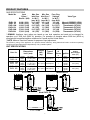
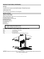
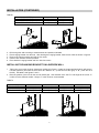
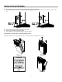
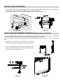
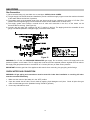
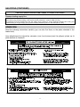
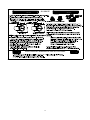
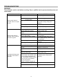
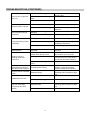
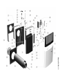
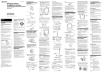
OWNER’S OPERATION AND
INSTALLATION MANUAL
FOR MODELS
GRAVITY
DIRECT VENT
WALL FURNACE
DVEL 8, DVEL 12, DVEL 20
WARNING: If the information in this
manual is not followed exactly, a fire or
explosion may result causing property
damage, personal injury or loss of life.
AVERTISSEMENT. Assurez-vous de bien
suivre les instructions données dans cette
notice pour réduire au minimum le risque
d’incendie ou d’explosion ou pour éviter tout
dommage matériel, toute blessure ou la mort.
Do not store or use gasoline or other
flammable vapours and liquids in the
vicinity of this or any other appliance.
Ne pas entreposer ni utilliser d’essence ni
d’autres vapeurs ou liquides inflammables
dans le voisinage de cet appareil ou de tout
autre appareil.
WHAT TO DO IF YOU SMELL GAS
• Do not try to light any appliance.
• Do not touch any electrical switch;
do not use any phone in your
building.
• Immediately call your gas supplier
from a neighbour’s phone. Follow
the gas supplier’s instructions.
• If you cannot reach your gas
supplier, call the fire department.
QUE FAIRE SI VOUS SENTEZ UNE ODEUR DE
GAZ:
• Ne pas tenter d’allumer d’appareils.
• Ne touchez à aucun interrupteur. Ne pas
vous servir des téléphones dans le
bâtiment où vous vous trouvez.
• Appelez immédiatement votre fournisseur
de gaz depuis un voisin. Suivez les
instructions du fournisseur.
• Si vous ne pouvez rejoindre le fournisseur
de gaz, appelez le service des incendies.
L’installation et l’entretien doivent être assuré
par un installeteur ou un service d’entretien
qualifié ou par le fournisseur de gaz.
Installation and service must be
performed by a qualified installer,
service agency or the gas supplier.
This appliance may be installed in an
aftermarket, permanently located,
manufactured home (USA only) or
mobile home, where not prohibited by
local codes.
This appliance is only for use with the
type of gas indicated on the rating
plate. This appliance is not convertible
for use with other gases, unless a
certified kit is used.
Cet appareil peut être installé dans une maison
préfabriquée (É.-U. Seulement) ou mobile déjà
installée à demeure si les règlements locaux le
permettent.
Cet appareil doit être utilisé uniquement avec
le type de gaz indiqué sur la plaque
signalétique. Cet appareil ne peut être converti
à d´autres gaz, sauf si une trousse de
conversion est utilisée.
1
CONTENT
Section
Preface
Product Identification
Product Features
Installation
Gas Piping
Operation
Cleaning and Maintenance
Troubleshooting
Service and Maintenance
Parts List
Page
1
2
3
4-9
10-11
11-14
14-15
16-18
18
19-23
This gas appliance must not be connected to a chimney flue serving a separate solid-fuel
burning appliance.
IMPORTANT FOR YOUR SAFETY
• Improper installation, adjustment, alteration, service, or maintenance can cause property
damage, personal injury or loss of life. Refer to this manual.
• Installation and service must be performed by a qualified installer, service agency, or the
gas supplier.
Do not use this appliance if any part has been under water. Immediately call a qualified
service technician to inspect the appliance and to replace any part of the control system
and any gas control which has been under water.
Ne pas se servir de cet appareil s’il a été plongé dans l’eau, complètement ou en partie.
Faire inspector l’appareil par un technicien qualifié et remplacer toute partie du système de
contrôle et toute commande qui ont été plongées dans l’eau.
PRODUCT IDENTIFICATION
Figure 2
2
PRODUCT FEATURES
GAS SPECIFICATIONS
Model No.
DVEL 8N
DVEL 8L
DVEL 12N
DVEL 12L
DVEL 20N
DVEL 20L
Input
Power *
Btu/Hr. / (kW)
8,000 / (2.32)
8,000 / (2.32)
11,000 / (3.20)
11,000 / (3.20)
17,000 / (4.94)
17,000 / (4.94)
Max. Gas
Min. Gas
Pres. Reg.
Inlet Pres. Inlet Pres.**
Settings
In. W.C. /
In. W.C. /
In. W.C. /
(mm. W.C.) (mm. W.C.) (mm. W.C.)
10,5 / (267) 4,5 / (114)
3,5 / (89)
14 / (355)
11 / (280)
10 / (254)
10,5 / (267) 6,4 / (162)
5,4 / (137)
14 / (355)
11 / (280)
10 / (254)
10,5 / (267) 4,5 / (114)
3,3 / (84)
14 / (355)
11 / (280)
10 / (254)
Valve Type
Manual (COPRECI 18700)
Manual (COPRECI 18700)
Thermostatic (SIT 630)
Thermostatic (SIT 630)
Thermostatic (SIT 630)
Thermostatic (SIT 630)
* REMARK: Appliance input ratings are based on sea level operation and need not be changed for
operation up to 2000 feet (609.9 m) elevation. For operation at elevation above 2000 feet (609.9 m)
manufactured to specified deration conditions for Canada and the United States.
**NOTE: Minimum Gas Inlet Pressure for purpose of input adjustment.
The efficiency rating of the appliance is a product thermal efficiency rating determined under continuous operating
conditions and was determined independently of any installed system.
UNIT SPECIFICATIONS
Model No.
DVEL 8N
DVEL 8L
DVEL 12N
DVEL 12L
DVEL 20N
DVEL 20L
Dimensions
Inch / (mm)
Height:
Width:
Depth:
Height:
Width:
Depth:
Height:
Width:
Depth:
20 / (508)
13 5/8 / (346)
7 3/8 / (187)
20 / (508)
17 3/8 / (441)
7 5/8 / (194)
20 / (508)
27 3/8 / (695)
8 3/8 / (213)
No.
of
Burner Ignition
s
Weight
Lbs. /
(kg.)
Type of
Burner
27 / (12.2)
Atmospheric
1
33.7 / (15.3)
Atmospheric
1
48.7 / (22.1)
Atmospheric
2
Model DVEL 8
Piezoelectric
ignitor
Piezoelectric
ignitor
Piezoelectric
ignitor
Model DVEL12
Model DVEL 20
3
Standard
Heating
Space Square
Feet / (m2)
200 / (18.6)
275 / (25.6)
425 / (39.5)
PRODUCT FEATURES (CONTINUED)
NOTICE
A qualified service person must install the heater. Follow all local codes.
CHECK GAS TYPE
Use only the type of gas indicated on the rating plate.
INSTALLATION
INSTALLATION ITEMS
Before installing heater, make sure you have the items listed below.
n Piping (check local codes)
n Sealant (resistant to propane gas)
n Manual shutoff valve
n Ground joint union
n Test gauge connection
n Sediment trap
n Tee joint
n Pipe wrench
The installation location shall provide the following;
a) adequate combustion and ventilation air, and
b) adequate accessibility clearances for servicing.
MINIMUM CLEARANCE FROM COMBUSTIBLE CONSTRUCTION
Rear............................... 0 Inches/0mm (to bracket)
Sides.............................. 6 Inches/152mm
Top................................. 36 Inches/914mm
Floor............................... 6 Inches/152mm (to top of carpeting, tile, etc.)
Figure 4
NOTICE: Maintain the minimum clearances shown in figure 4. If you can, provide greater clearances from
floor, ceiling and adjoining wall.
4
INSTALLATION (CONTINUED)
This appliance may be installed in an aftermarket, permanently located, manufactured home (USA only) or
mobile home, where not prohibited by local codes.
This appliance is only for use with the type of gas indicated on the rating plate. This appliance is not
convertible for use with other gases, unless a certified kit is used.
IMPORTANT: This appliance should only be installed by a qualified installer.
The installation must conform with local codes or, in the absence of local codes, with the National Fuel Gas Code,
ANSI Z223.1, or Canadian Installation Code, CAN1-B149.
Installer l’appareil selon les codes ou règlements locaux, ou en l’absence de tels règlements, selon les codes
d’installation Canadian Installation Code, CAN1-B149.
A manufactured home (USA only) or mobile home OEM installation must conform with the Manufactured Home
Construction and Safety Standard, Title 24 CFR, Part 3280, or, when such standard is not applicable, the Standard for
Manufactured Home Installations, ANSI Z 225.1, or Standard for Gas Equipped Recreational Vehicles and Mobile
Housing, CSA Z 240.4.
IMPORTANT
•
•
•
•
•
•
The appliance area must be kept clear and free from combustible materials, gasoline, and other flammable
vapors and liquids.
Due to high temperatures, the appliance should be located out of traffic and away from furniture and
draperies.
Children and adults should be alerted to the hazards of high surface temperature and should stay away to
avoid burns or clothing ignition.
Young children should be carefully supervised when they are in the same room as the appliance.
Clothing or other flammable material should not be placed on or near the appliance.
Any safety screen or guard removed for servicing an appliance must be replaced prior to operating the
appliance.
Installation and repair should be done by a qualified service person. The appliance should
be inspected before use and at least annually by a qualified service person. More frequent
cleaning may be required due to excessive lint from carpeting, bedding material, etc. It is
imperative that control compartments, burners and circulating air passageways of the
appliance be kept clean.
WARNING: Failure to position the parts in accordance with these diagrams, or failure to use only parts
specifically approved with this appliance may result in property damage or personal injury.
AVERTISSEMENT: Risque de dommages ou de blessures si les pièces ne sont pas installées conformément à
ces schemas et ou si des pièces autres que celles spécifiquement aprouvées avec cet appareil sont utilisées.
INSTALLING THE APPLIANCE
Separate the hanging bracket from the appliance by removing two screws on the top and two nuts at the bottom.
INSTALLING THE HANGING BRACKET ON A NON-COMBUSTIBLE WALL (i.e., MASONRY
BLOCK OR CONCRETE)
1.
Draw the position of the hole for the air-vent intake pipe, taking into account the minimum clearances mentioned in
figure 4. See diameter of the hole “D” and height to the center “C” in table 1 and figure 5 for the different models.
Height “C” is the minimum recommended.
5
INSTALLATION (CONTINUED)
TABLE1
MODEL
DVEL 8N - DVEL 8L
DVEL 12N - DVEL 12L
DVEL 20N - DVEL 20L
C
19 ½” (495 mm)
19 ½” (495 mm)
19” (483 mm)
D
6 ¾” (172 mm)
7 ¾” (197 mm)
8 ¾” (222 mm)
Figure 5
2.
3.
4.
5.
6.
Figure 6
Drill through the wall according to measurements and positions indicated.
Place hanging bracket over the hole. After leveling the hanging bracket, mark the four holes as shown in figure 6.
Remove the hanging bracket and drill the four holes.
Insert in each hole the anchors provided.
Place back the hanging bracket and fix it with four screws.
INSTALLING THE HANGING BRACKET ON A WOODEN WALL
1.
2.
Taking into account the minimum clearances mentioned in figure 4, locate the closest wall stud (which will serve to
hold the appliance) and mark the hole center at a distance “A”, (if wall stud is at the right), or “B”, (if the stud is at
the left). See table 2 and figures 7 and 8.
Draw the position of the hole for the vent-air intake pipe. See diameter of the hole “D” and height to the center “C”
in table 2 for the different models. Height “C” is the minimum recommended.
TABLE 2
MODEL
DVEL 8N - DVEL 8L
DVEL 12N - DVEL 12L
DVEL 20N - DVEL 20L
A
5 9/16” (141 mm)
7 13/16” (198 mm)
13 11/64” (335 mm)
B
3 31/32” (101 mm)
5 7/16” (138 mm)
10 7/8” (276 mm)
Figure 7
C
19 ½” (495 mm)
19 ½” (495 mm)
19” (483 mm)
Figure 8
6
D
6 ¾” (172 mm)
7 ¾” (197 mm)
8 ¾” (222 mm)
INSTALLATION (CONTINUED)
3.
4.
Drill through the wall according to measurements and positions indicated.
Place wall bracket over the hole. After leveling the hanging bracket, mark the four holes as shown in figures 9 and
10.
Figure 9
5.
6.
7.
Figure 10
Remove the hanging bracket and drill the four holes.
Insert in each hole the anchors provided.
Place back the hanging bracket and fix it with four screws.
MOUNTING THE HEATER ON HANGING BRACKET
Place the heater on the hanging bracket and fix it with its screws. (See Figure 11 and 12).
Figure 12
Figure 11
ATTENTION:
THE ATTACHED SET
OF THREE MARKING
PLATES (RATING
PLATE, OPERATION
INSTRUCTIONS, AND
SAFETY PLATE)
MUST NOT BE
REMOVED FROM THE
APPLIANCE AT ANY
TIME.
Figure 13
7
INSTALLATION (CONTINUED)
INSTALLING THE VENTING SYSTEM
These models of wall furnaces are designed for direct venting through a wall.
Only venting components specifically approved for these furnaces may be used.
The flow of combustion gases and ventilation air must not be obstructed.
Minimum clearance between pipes and combustible materials is one (1) inch (25.4 mm).
Vent terminal must be 18.0” away from an adjacent wall.
Minimum clearance between vent cap and combustible material 1 ¾”.
IMPORTANT: The appliance’s venting system should be inspected at least once a year and immediately cleaned if
necessary.
IMPORTANT: THE VENT-AIR INTAKE SYSTEM MUST BE PROPERLY INSTALLED TO INSURE PROPER AND
SAFE OPERATION. THE VENT-AIR INTAKE SYSTEM MUST ALSO BE PROPERLY RE-INSTALLED AND RESEALED TO INSURE PROPER AND SAFE OPERATION.
Warning: Failure to position the parts in accordance with these diagrams or failure to use only parts specifically
approved with this appliance may result in property damage or personal injury.
Avertissement: Risque de dommages ou de blessures si les pièces ne sont pas installées conform´ment à ces
schémas et ou si des pièces autres que celles spécifiquement approuvées avec cet appareil sont utilisées.
CAUTION: ALL JOINTS MUST BE AIR-TIGHT.
The venting system consists of: one injected-aluminum cap (A), one vent pipe (B), one vent-air intake pipe (C), one rod
(D), one nut (E), one outdoor mounting plate (F) and one silicon-rubber ring (G). (See figure 14).
Figure 14
1.
2.
Measure thickness of the wall as shown in figure 15.
If pipes (B), (C) and the rod are long, trim them according to thickness of the wall, as shown in the following table.
TABLE 3
Lengths of pipes and rod.
3.
4.
5.
6.
Figure 15
vent pipe (B)
wall thickness
+ 3 3/8“ (86 mm)
vent-air intake pipe (C)
wall thickness
+ 2 1/2“ (64 mm)
Rod (D)
wall thickness
+ 5 7/8“ (149.5 mm)
The hole at the outside of the wall must be a square of 11 ½” (290 mm) x 11 ½” (290 mm). (See figure 17).
From the outside of the wall, screw the rod slightly onto support located inside the appliance flue outlet.
Slide pipes (B) and (C) through the hole in the wall, and connect them to the appliance flue outlet and air intake,
respectively.
The outdoor mounting plate and the silicon-rubber ring should be installed between the vent cap and the exterior
wall. The plate must be positioned flush to the wall and with its standoffs inserted into the wall and sealed with a
non-hardening mastic (silicone caulk). (See figure 17).
Position the outdoor mounting plate so that the vent-air intake pipe has a slight downward slope to the outside. The
downward slope is necessary to prevent the entry of rainwater.
8
INSTALLATION (CONTINUED)
7.
8.
Before attaching the vent cap to the exterior wall, run a bead of non-hardening mastic (silicone caulk) around its
outside edge, so as to make a seal between it and the plate. (See figure 17).
Place cap and screw nut “E”, until cap leans against the plate. (See figures 16 and 17).
Figure 16
Figure 17
INSTALLING THE THERMOSTAT SENSOR (MODELS DVEL12 AND DVEL20)
In order to protect the thermostat sensor from any damage during shipping, or while handling it before it is definitely
installed, the thermostat sensor has not been attached to its final location in the appliance.
So, once the heater is installed, the thermostat sensor must be placed and secured in position. To do so, follow these
steps:
1. Separate the front panel of the appliance by removing the
two nuts in the bottom and sliding it up as shown in figure 18.
2. Place the thermostat sensor under the right bottom of the
bracket and fix it with the same nut that fixes the appliance to
bracket as shown in figures 19 and 20
Figure 18
Figure 19
Figure 20
9
GAS PIPING
Gas Connection
1) We recommend using only new black iron or steel pipe. CHECK LOCAL CODES.
2) The gas supply line shall be sized and installed to provide a sufficient supply of gas to meet the maximum demand
of the heater without undue loss of pressure.
3) The sealant used on the threaded joints of the gas pipe must be a type resistant to the action of L.P.Gas. (This
sealant should be applied lightly to main threads to ensure excess sealant does not enter lines.)
4) The supply system must include a manual shut off valve and connection in the line, so the heater can be
disconnected for servicing. (See Figure 21).
5) Include a drip leg (trap) and a plugged 1/8” N.P.T. tapping in the line. The tapping should be accessible for test
gauge connections upstream of the gas supply connection to the heater.
Figure 21
WARNING: For L.P.Gas, use PRESSURE REGULATED gas supply. Do not directly connect LP supply tank to the
pressure regulator on the heater. The LP supply tank must have its own separate pressure regulator that can reduce
the supply tank gas pressure down to a maximum of 14 inches (355 mm) of water column pressure.
IMPORTANT: Hold the gas inlet of the appliance with wrench when connecting it to gas piping and/or fittings.
CHECK AFTER GAS CONNECTION
WARNING: All gas piping and connections must be tested for leaks after installation or servicing. All leaks
must be corrected immediately.
1.
2.
3.
Make sure the control of the heater is in the “OFF” position.
Open the manual shut off valve. Test for leaks by applying liquid detergent to all joints. Check all joints from gas
meter to thermostat gas valve. (Bubbles forming indicate a gas leak)
Correct any leak defect at once.
10
GAS PIPING (CONTINUED)
CAUTION: NEVER USE AN OPEN FLAME TO CHECK FOR LEAKS
Pressure testing supply line
ATTENTION: This appliance and its appliance main gas valve must be disconnected from the gas supply piping
system during any pressure testing of that system at test pressures in excess of ½psi (3,5 kPa).
The appliance must be isolated from the gas supply piping system by closing equipment shutoff valve during any
pressure testing of the gas supply piping system at test pressures equal to or less than ½psi (3,5 kPa).
OPERATION
Read the following instructions carefully (you can also find them on the plates attached to the
heater back):
Lisez attentivment les instructions suivantes (vous les trouverez aussi les plaques jointes sur la
partie derrière de l’appareil).
11
OPERATION (CONTINUED)
Pilot Burner
12
ALLUMAGE
Veilleuse
POUR COUPER L'ADMISION DE GAZ DE L'APPAREIL
13
OPERATION (CONTINUED)
CAUTION
Do not try to adjust heating levels by using the manual shutoff valve.
IMPORTANT
•
•
•
•
•
•
•
Do not dry clothes over the heater.
Do not spray any aerosol near the heater when functioning. Do not store these elements near the appliance.
Do not touch grill to avoid burns.
Avoid blocking air inlet and hot air outlet.
Do not spill water over the heater as it may cause corrosion or damage.
Do not touch vent cap while heater is operating, to avoid burns.
If you smell gas, shut off control valve, open doors and windows and do not light any electrical fixture near the
heater. Call your Gas Supplier.
NOTE: It is normal for the new wall furnace to give some odor the first time it is burned. This is due to the curing of the
paint and any undetected oil from the manufacturing process.
It is recommended to burn a new wall furnace for at least two (2) hours the first time that it is used.
CLEANING AND MAINTENANCE
WARNING
Turn off heater and let cool before cleaning.
CAUTION
You must keep control areas and circulating air passageways of heater clean. Inspect these areas of heater before
each use. Have heater inspected yearly by a qualified service person. Heater may need more frequent cleaning due to
excessive lint from carpeting, bedding material, etc.
Verify proper operation after servicing.
S’assurer que l’appareil fonctionne adéquatement une fois l’entretien terminé.
CABINET
Exterior
Use a soft cloth dampened with a mild soap and water mixture. Wipe the cabinet to remove dust.
Air Passageways
Use a vacuum cleaner or pressurized air to clean.
Vent Cap
Use a vacuum cleaner or pressurized air to clean.
Pilot and Burner
Periodically visually check the pilot and burner flames.
(View flames through view port)
Fig. 22
14
The correct flame pattern should be viewed by looking through the view port on top of the unit (Fig. 22).
The correct flame pattern of pilot and main burner are shown in figures 23, 24, 25 and 26.
PILOT FLAME
THERMOCOUPLE
PRIMARY FLAME: 1/4´´ - 3/8´´ (6 - 10 mm)
Model DVEL 20
Models
SECONDARY FLAME: 2´´ - 4´´ (50 - 100 mm)
DVEL 8
and 12
Fig. 24
Correct pilot burner flame pattern
Fig. 23
Correct main burner flame pattern
SECONDARY FLAME
PRIMARY FLAME
PILOT FLAME
THERMOCOUPLE
Fig. 25
Correct main burner flame pattern (top view)
Models DVEL 8 and 12
SECONDARY FLAME
PRIMARY FLAME
PILOT FLAME
THERMOCOUPLE
Fig. 26
Correct main burner flame pattern (top view)
Model DVEL 20
Cleaning the Main Burner Orifice and Main Burner
1.
2.
3.
4.
5.
6.
Turn OFF gas supply to the heater.
Remove casing assembly.
Disconnect burner tubing and remove orifice holder.
Apply compressed air the orifice holder assembly to remove dust, lint or spider webs.
Apply compressed air through the hole on the combustion chamber wall where the orifice holder was originally
located to remove dust, lint or spider webs.
As parts are being replaced in reverse order, check for gas leaks at all gas connections before replacing the
casing assembly.
15
TROUBLESHOOTING
WARNING
Turn off heater and let cool before servicing. Only a qualified service person should service and
repair heater.
OBSERVED PROBLEM
When ignitor button is
pressed, there is no spark
at pilot.
When ignitor button is
pressed, there is spark at
pilot but no ignition.
Pilot lights but flame goes
out when control knob is
released.
POSSIBLE CAUSE
1) Ignitor electrode broken.
REMEDY
1) Replace ignitor electrode.
2) Ignitor electrode not connected
to ignitor cable.
3) Ignitor cable pinched or wet.
2) Reconnect ignitor cable.
4) Broken ignitor cable.
3) Free ignitor cable if pinched by
any metal or tubing. Keep ignitor
cable dry.
4) Replace ignitor cable.
5) Bad piezo ignitor.
5) Replace piezo ignitor.
1) Gas supply is turned off or
manual shutoff valve closed.
2) Control knob not in PILOT
position.
3) Control knob not pressed in
while in pilot position.
4) Air in gas lines when installed.
1) Turn on gas supply or open
manual shutoff valve.
2) Turn control knob to PILOT
position.
3) Press in control knob while in
PILOT position.
4) Continue holding down control
knob. Repeat igniting operation until
air is removed.
5) Pilot is clogged.
5) Clean pilot orifice or replace pilot
assembly.
6) Gas regulator setting not correct. 6) Replace gas regulator.
1) Control knob not fully pressed in.
2) Control knob not depressed long
enough.
3) Manual shutoff valve not fully
open.
4) Thermocouple connection
looses at control valve.
5) Pilot flame not touching
thermocouple, which allows couple
to cool, causing pilot flame to go
out. This problem could be caused
by one or both of the following:
a) Low gas pressure.
b) Dirty or partially clogged pilot.
6) Thermocouple damaged.
1) Press in control knob fully.
2) After pilot lights, keep control knob
pressed in 30 seconds.
3) Fully open manual shutoff valve.
7) Control valve damaged.
Replace control valve.
16
4) Hand tighten until snug, then
tighten ¼ turn more.
5) a) Contact local gas company.
b) Clean pilot or replace pilot
assembly.
6) Replace thermocouple.
TROUBLESHOOTING (CONTINUED)
1) Burner orifice is clogged.
Burner does not light after
pilot is lit.
Delayed ignition of burner.
Burner backfiring during
combustion.
Yellow flame during burner
combustion.
2) Burner orifice diameter is too
small.
3) Inlet gas pressure is too low.
1) Contact local Gas Company.
2) Burner or pilot orifice is clogged.
2) Clean burner or pilot orifice or
replace it.
1) Clean burner orifice or replace it.
1) Burner orifice is clogged or
damaged.
2) Gas regulator defective.
2) Replace gas regulator.
1) Inlet pipe is blocked.
1) Remove the blockage.
2) Incorrect connections of pipes.
1) Connect pipes according to
installation instructions.
1) Replace gas regulator.
Slight smoke or odor during 1) Residues from manufacturing
initial operation.
processes.
1) Turning control knob to HI
position when burner is cold.
2) Air in gas line.
Heater produces a
whistling noise when
burner is lit.
3) Dirty or partially clogged burner
orifice.
Heater produces a
1) Metal expanding while heating or
clicking/ticking noise just
contracting while cooling.
after burner is lit or shut off.
1) Gas leak (see WARNING
Heater produces unwanted
statement below).
odors.
Gas odor even when
control knob is in OFF
position.
3) Contact local Gas Company.
1) Manifold pressure is too low.
3) Gas regulator defective
Heater shuts off in use.
1) Clean burner orifice or replace
burner orifice.
2) Replace burner orifice.
1) Problem will stop after a while of
operation.
1) Turn control knob to LO position
and let warm up for a minute.
2) Operate burner until air is
removed from line. Have gas line
checked by local Gas Company.
3) Clean burner orifice or replace it.
1) Low line pressure.
1) This is common with most
heaters. If noise is excessive,
contact qualified service person.
1) Locate and correct all leaks (see
Checking Gas Connections, page
12)
1) Contact local Gas Company.
2) Pilot is partially clogged.
2) Clean pilot.
1) Gas leak. See WARNING
statement below.
1) Locate and correct all leaks (see
Checking Gas Connections, page
12)
2) Replace control valve.
2) Control valve defective.
17
TROUBLESHOOTING (CONTINUED)
WARNING
If you smell gas:
n
n
n
n
n
Shut off gas supply.
Do not try to light any appliance
Do not touch any electrical switch, do not use any phone in your building.
Immediately call your gas supplier from a neighbor’s phone. Follow the gas supplier’s instructions.
If you cannot reach your gas supplier, call the fire department.
SERVICE AND MAINTENANCE
WARNING
Turn off heater and let cool before servicing.
Verify proper operation after servicing.
REPLACEMENT PARTS
NOTE: In order for you to receive credit for parts replaced under warranty, only original replacements parts
must be returned the authorized distributor.
A) UNDER WARRANTY:
Contact authorized dealers of this product. If they are unable to supply original replacement part(s), call the authorized
distributor. Be prepared to indicate name, address, model number, and how heater was malfunctioning, type of gas
used and purchase date. In most cases, the defective part will be requested to be returned to the authorized distributor.
B) NOT UNDER WARRANTY:
Contact authorized dealers of this product. If they are unable to supply original replacement part(s), call the authorized
distributor. Be prepared to indicate model number and replacement part(s) number.
When calling the authorized distributor have ready:
n model number of your heater
n the replacement part number
Authorized
Distributor
in USA and Canada:
18
19
Model DVEL 8
19
20
Model DVEL 12
21
Model DVEL 20
PARTS LIST
ITEM No.
1
2
3
4
5
6
7
8
9
10
11
12
13
14
15
16
17
18
19
20
21
22
23
24
25
26
27
28
29
30
31
32
33
34
PARTS No.
DESCRIPTION
DVEL 8
05070
DVEL 12
DVEL 20
05220
05325
02380101B
01196101A
05146
05262
05359
05046
05090
01212001
01090001
05175
05277
05386
05075
05225
05330
01192701 - 01190801B
01193602
010210C
01021001C 01021002C
05089
05245
05256
05134
05251
05338
01212401
-05232 - 01001901A
05078
-01021307
-01021301
05083
05228
05334
01082001
02230113
01082002
01081403
01082102
01081403
01141502
01143309
01143309
01090002
011433
011433
01021713D
011433
011433
01021714D
05152
05267
05385
01143301C
01194202
01194205
02340101
01143130
01022111B
05170
01160503
01001808
01001807A
01160502
01051402
05113
05266
05387
22
Front panel
Mark
Nut
Grill guard
Glass frame
Lateral radiation shield
Glass
Gasket
Combustion chamber
Back
Bolt and nut
Nut
Vent cap
Vent-air intake pipe
Vent pipe
Rod
Thermostat Sensor bracket
Knob support
Elbow 3/8 NPT x 3/8 NPT
Elbow 1/4 BSP x 1/4 BSP
Bracket
Burner orifice Natural Gas
Burner orifice L.P.G.
Injector holder
Pilot gasket
Pilot assembly Natural Gas
Pilot assembly L.P.G.
Hanging bracket
Thermocouple
Ignitor wire
Piezo-ignitor bracket
Spring
Knob position marking ring
Spring
Piezo-ignitor
Outdoor mounting plate
PARTS LIST (CONTINUED)
ITEM No.
35
36
37
38
39
40
41
42
43
44
45
46
47
48
49
50
51
52
53
54
55
56
57
58
PARTS No.
DVEL 8
02220702
DESCRIPTION
DVEL 12
DVEL 20
02220705
01140701D
02100117E
01140908C
01212301
01210603
010003
05097
01190403
05269
05364
05268
05363
05257
05376
01160902
02830138B
02830140
02830137B 02830141B
011935A
02830139A
05240
---
012123B
----05096
--01210408G
01210404G
05137
--02830110B
02830109B
--01024001
05087
01052001
01052002
01160901
---01143302
01143127
01143306
05100 --05101
05066
05201
-05355
02330101
01080406
01080405
--05246
23
Ignitor rod
Control Knob
Control panel
Ignitor button
Knob rod
Adapter
Washer
Gas control valve bracket
Bolt
Gas control Valve Natural Gas
Gas control Valve L.P.G.
Top Radiation Shield
Nipple 1/4 BSP x 3/8 NPT
Burner tubing
Pilot tubing
Nut
Gas main inlet tubing
Radiation shield
Pressure Regulator Natural Gas
Pressure Regulator L.P.Gas
Pressure Tap Fitting
Front radiation shield
Spark plug
Pilot burner orifice Natural Gas
Pilot burner orifice LPG
Pressure regulator bracket
Silicon-rubber ring
Authorized
Distributor
in USA and Canada:
ESKABE S.A.
Cod. Mat.: XXXX.XX.XXX
Ruta 2 No 323
(7600)Mar del Plata
Pcia. de Buenos Aires
Argentina
24