1
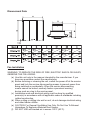
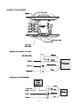
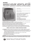
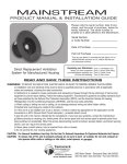
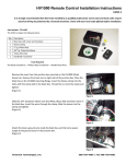
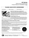
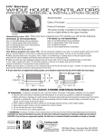
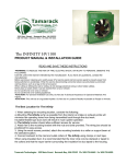
The DRAGON
Tamarack
Technologies, Inc.
Ventilation Solutions
www.tamtech.com
Date of Purchase
Place of Purchase
Dimensional Data
Fan Installation
WARNING: TO REDUCE THE RISK OF FIRE, ELECTRIC SHOCK OR INJURY,
OBSERVE THE FOLLOWING:
(a) Use this unit only in the manner intended by the manufacturer. If you have any questions contact the manufacturer.
(b) Before servicing or cleaning the unit, switch the power off at the service panel and lock the service disconnecting means to prevent power from being switched on accidentally. When the service disconnecting means cannot be locked; securely fasten a prominent warning device such as a tag to the service panel.
(c) Installation work and electrical wiring must be done by qualified person(s) in accordance with all applicable codes & standards including related construction.
(d) When cutting or drilling into wall or roof, do not damage electrical wiring and other hidden utilities.
(e) CAUTION: For General Ventilating Use Only. Do Not Use To Exhaust Hazardous Or Explosive Materials And Vapors.
(f) DO NOT USE with heated air in excess 140˚F (60˚C).
1
Select Fan Location
When selecting a location to install the Dragon fan, take into consideration the
application of the product, the locations of fresh air intakes, and sound generated
by the Dragon unit. If ductwork is to be used, consider the path of the ducting
material.
The fan should be located a minimum of 6 feet horizontally and 8 feet vertically
from any fresh air intakes for HVAC systems, heat recovery systems, etc. to
prevent exhaust air streams from being re-introduced into the occupied space.
Doors or windows that are frequently opened during pleasant seasons may also
be considered fresh air intakes so keep this in mind when selecting the location
of the Dragon.
Locate Mounting and Through Holes
Once the location on the exterior wall where the fan is to be mounted has been
selected, mark all screw and hole locations utilizing the included template. Cut
the holes through the wall for the duct connection and for the electrical conduit.
Measure the thickness of the wall and the length of the duct flange that is part
of the Dragon fan. Cut a length of duct (not supplied) so that once connected to
the duct flange, it will eliminate air leakage into the wall cavity. Attach grille or fan
guard (not supplied) to prevent objects from entering ductwork and fan.
If mounting the fan on a masonry wall, drill four holes and insert wall anchors. If
mounting to wooden structure, you will utilize wood screws to secure the Dragon
to the wall. If the fan is to be mounted on a wall surface which is not flush such
as lapped siding, a mounting plate to provide for a flush fit needs to be made.
Mount the Fan
Insert electrical supply through the wall. Attach the duct extension to the Dragon
making sure that the connection is secure. Apply a generous amount of exterior
silicone caulk (not supplied) to backplate of the fan to ensure an airtight/
waterproof connection between the fan and the wall surface. If a mounting frame
is used in conjunction with lapped siding, be certain to apply a generous amount
of caulk between the frame and the wall as well as the fan backplate and the
frame. Mount the fan to the wall.
Note: Be certain to make an airtight seal around all interior wall penetrations before attaching duct work.
Electrical Connection
All Dragon series fans operate from a standard 120V 60Hz A.C. electrical supply.
All wiring must be carried out in accordance with applicable state and local
2
buildings codes. Note: A licensed Electrician may be needed. If unsure,
consult with your local Electrical Inspector.
WIRING INSTRUCTIONS
WARNING! Make sure that power supply is disconnected and locked to
prevent accidental activation.
1. Remove the screws securing the terminal box cover plate located on the fan
motor mounting bracket. All fan motor and capacitor connections are pre-wired
to the electrical terminal strip. A 3/8” romex type cable restraint connector will be
needed to secure the wiring through the knockout provided on the side of the
terminal box.
2. Bring incoming electrical service through the romex connector and the fan
electrical service opening. Using a small regular screwdriver, tighten the neutral
(white) wire of the incoming 115V power supply under the open terminal strip port
opposing the motor Blue wire. Tighten the line (black) wire of the incoming supply
under the open terminal opposing the motor Black wire. Now, secure the source
ground to the open terminal strip opposing the Green/Yellow Wire.
3. Secure the romex connector to the terminal box. Secure the incoming supply
using the romex connector. Replace the fan terminal box cover.
4. Apply a generous bead of silicone caulk around the electrical provision hole in
the backplate of the fan to provide for a secure seal.
CONTROLS
The Dragon can be controlled by several methods. A standard SPST wall switch
or 2, 3-way “hallway” switches. There are many wall mounted crank timers with
2,4 or 6 hour setting available. Some automatic garage door openers will allow
the Dragon to operate for a preset interval after the door opens or closes. Check
with the manufacturer of your door opener about these options.
MAINTENANCE INSTRUCTIONS
1. Since fan bearings are sealed and provided with an internal lubricating
material, no additional lubrication is necessary.
2. It is recommended that the cover screen is checked on a regular basis to
check for any obstructions and the cover is removed and the motor and wheel
are inspected and cleaned as necessary.
No other maintenance is necessary.
3
WIRING DIAGRAMS
4
LIMITED WARRANTY
If, within the period of three years from the date of purchase, the Dragon (the
Product) is defective or malfunctions in normal home use, Tamarack Technologies,
Inc. will repair or replace the Product at its discretion without charge for labor or
materials. Customer is responsible for shipping charges.
Conditions, Exclusions, and Limitations-This Warranty is subject to the following
conditions, exclusions and limitations:
This Warranty does not cover problems resulting from installation,
operation or maintenance that has been undertaken other than
in accordance with the instructions. This Warranty does not
cover problems resulting from defects in or caused by associated
equipment (furnaces, solaria, etc.); From repairs or modifications
attempted by persons other than Tamarack Technologies, Inc.;
From abuse, accidental or shipping damage or acts of God. This
Warranty does not apply to the Product used outside the United
States, its territorial possessions, and Canada. Except as set forth
above, no express or implied Warranty is given or authorized by
Tamarack Technologies, Inc. And all other such warranties are
expressly disclaimed. Any warranty or merchantability of fitness
for any particular purpose shall be limited to the warranty
hereunder. Moreover, any liability of Tamarack Technologies, Inc.
For the product shall be limited to the replacement value of the
product. In no event shall Tamarack Technologies, Inc. be liable
for any incidental damages or for any consequential property or
commercial damages, irrespective of the cause thereof, occurring
either during or after the warranty period, including without
limitation any damages to any part of a building or its contents.
Note: Some states do not allow the exclusion or limitation of
incidental or consequential damages and some states do not allow
limitations on how long an implied warranty lasts, so the above
limitations or exclusions may not apply to you. This Warranty gives
you specific legal rights and you may also have other rights that
vary from state to state.
Tamarack
Technologies, Inc.
Ventilation Solutions
www.tamtech.com
Tamarack Technologies, Inc.
320 Main Street
Buzzards Bay, MA 02532
800-222-5932
P/N DF.1
5