1
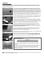
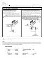
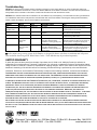
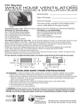
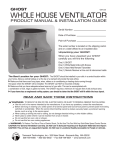
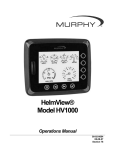
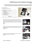
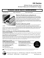
HV Series
Whole House Cooling Fans
Product Manual & Installation Guide
HVM.01
PLEASE LEAVE WITH HOMEOWNER
Serial Number _________ Date of Purchase __________Point of Purchase _________________
What the HV whole house cooling fans do
The HV is used to assist the natural cooling process in the house. When the
outside temperature drops below the inside temperature, the cooler outside air
can be used to cool the house. The HV will pull the cooler air from the outside,
through the house, up into the attic and push the hot air outside. The HV is a
fan product and will not cool the house below the outside air temperature or
create a noticeable breeze. The HV can be used for as long as needed to cool
the house to the desired level. It can also be used any time you want to change
the air in the house.
The best location for your HV
Air will always take the path of least resistance. The HV should be located so
that it is as central as possible to the area that you want to cool. Above a
central hallway or at the top of a stairwell provide the best airflow. The fan can
also be mounted vertically, exhausting through a knee wall into an under-the-eaves attic space. Cooler outside air should
be able to move through the window, the space that needs to be cooled, and exhaust out through the fan into the attic.
Warning: Not to be used over cooking appliances.
HV1000
Before installing your HV: Read all instructions carefully
► Some state and local electrical codes require fan products be installed by a licensed electrician. Check with your local
code officials before installation.
► Make sure that you have adequate net free exhaust area out of your attic. A minimum of 2 square feet is required for
the HV1000 and 3-1/2 square feet for the HV1600. This can be accomplished with a combination of roof, ridge, soffit or
gable end vents or other attic exhaust points.
► Make sure that there is enough clearance for the doors to open. Minimum requirement for the HV with R22 insulating
doors (HV1000 and HV1600-GR) is 11” and 12” for models with R38 insulating doors (HV1000-DB and HV1600-GDR).
► Make sure that there aren’t any pipes, wires, rafters, or air conditioning or heating ducts running through the space
where the HV will be installed and that the doors will face an unoccupied area.
Unpacking your HV: When you have unpacked your HV carefully you will find the following:
HV1000 (silver faced insulation)
HV1600 (gold faced insulation)
One (1) HV1000 Whole House Cooler
One (1) White Metal Grille w/(6) White Screws
One (1) Package of Foam Gasket
One (1) Metal Electrical Box Cover
One (1) Wall Switch (SPST)
Six (6) #8x3/4 Screws
One (1) Grounding Screw (green)
One (1) HV1600 Whole House Cooler
One (1) White Metal Grille w/(6) White Screws
One (1) Package of Foam Gasket
Six (6) #8x3/4 Screws
One (1) Hand Held Remote Transmitter
DO NOT
PULL ON,
CARRY BY
OR STRESS
THE DOORS
Please note the serial number, date of purchase and the point of purchase on the top of this page for handy
reference. The serial number is located on a label affixed to the HV next to the junction/utility box.
©Tamarack Technologies, Inc.• 320 Main Street • PO Box 963 • Buzzards Bay, MA 02532
508-759-4660 • 800-222-5932 • Fax 508-759-6001
www.tamtech.com
Installation
Tools and supplies needed
You will need two pieces of 2x stock to match your existing framing, a saw to cut the hole in the ceiling, a hammer or
screw gun to attach the blocking to the existing joists and both a flat head and Phillips head screw driver to attach the
grille and for the electrical work.
1. Cut a hole in the ceiling under where the HV will be installed. The dimensions of the
hole should be no greater than 23 1/2" x 14". This will allow for the grille to cover the
exposed sheetrock edges. Suggested methods for making the proper sized hole in the
ceiling are; Cut a pilot hole under where the fan will be installed. Cut toward the edge to
find the joist pattern and lay out the fan opening on the ceiling. (Figure 1) ; or mark the four
corners of the opening from the attic side and draw a line between each of the four
corners to lay out the fan opening; or use a stud finder to locate the joists, cut a template
from the fan packaging material and use the template to lay out the fan opening.
Figure 1
2. The fan housing will fit either 16” or 24” on center framing. Cut two pieces of 2x stock
(2 x 6 or 2 x 8 etc.) of the same dimension as the existing joists. Add these pieces of
framing to form a box between the joists. (Figure 2).
3. Install the foam gasket (supplied) on the top of the joists and added framing. Check
the joint between the ceiling and the 2x stock. Some types of ceilings are spaced away
from the joists. Any gap between the 2x’s and the ceiling should be sealed prior to final
installation. (Figure 3) Use a low expansion spray foam sealant (not supplied).
Figure 2
4. Set the HV on the gasket with the doors facing to open into the attic. The lower
housing will fit into the box with the mounting flanges overlapping the joists. (Figure 4)
The HV should not be forced into this opening. Forcing it into place may cause the
doors to bind and not function properly.
5. If desired, secure the HV to the top of the joists using the screws provided. When
fastening the mounting flange to the joists care should be taken that all screws are
tightened evenly to avoid the door hinges binding.
Figure 3
6. Wire the HV as shown in the Wiring section of this manual. It is recommended that the
wiring of the HV be done by a licensed electrician.
7. Check the HV for proper operation. Turn the unit on and allow 30 seconds for the
doors to fully cycle open and the fans to start. DO NOT FORCE THE DOORS OPEN.
8. Install the grille (6 screws included) on the ceiling below the fan. (Figure 5)
Operating your HV
Figure 4
IMPORTANT
Be sure at least one window is open when the fan is operating
HV1000 - The HV1000 is operated by the wall switch installed per the wiring
instructions.
HV1600 - The HV1600 is controlled by the hand held remote transmitter. Button 1
is used to turn the unit On/Off and button 2 for High/Low. Additional controls,
when used, may override the remote control. See the Wiring section of this
manual for further details.
Figure 5
Some owners find the installation has a more finished look when the inside of the blocking has been painted before
the unit is installed and the grille is put in place.
Wiring
Important - Because of the motorized doors, wiring the HV is different than a normal ON/OFF fan. Please follow the
instructions carefully. Be sure to turn off power before wiring the HV Whole House Fan It is recommended that the
wiring of the HV be done by a licensed electrician.
The HV requires a constant source of power. Because the doors are motorized, they need power to open and power to
close. The fan operation is controlled internally.
HV1000
HV1600
There are three wires in the electrical box:
The HV1600 is connected to power through the line cord
WHITE, RED, and BLACK.
and must be plugged into a constant, grounded power
• Connect the WHITE wire to Line Neutral
source. When connected to power, it will be fully functional
• Connect the RED wire to Line Hot
with the hand held remote control unit. When any of the
• Connect the BLACK wire to a Switched Hot Feed
buttons on the remote control are pushed, the red indicator
When 115 VAC Hot is applied to it, the doors will
light should momentarily flash.
open. When 115 VAC Hot is removed, the doors will
Hardwiring the unit to wall switches using the BLUE and
close.
YELLOW wires will provide additional, manual control. The
• Connect the ground wire to the screw in the electrical
BLUE wire will provide on/off control and the YELLOW wire
box
will provide high or low speed control. Using a switch in the
ON position will override the remote control function.
Use only SPST (single pole, single throw) switches.
Drawing is not to scale
Drawing is not to scale
The HV whole house cooling fans are not for use with solid state speed controls
A Remote Control Kit for the HV1000 is available and may be purchased separately. Installation is quick and easy
and it may be installed at any time.
Care
All the motors in the HV are permanently sealed and do not require oiling. To keep dirt, dust and debris from the fans we
recommend that you periodically remove the grille from within the living space and dust the fan blades. Please remember
to make sure that the fan is OFF before dusting the fan blades.
Specifications
Voltage ……………………………. 115VAC 60 Hz
Power
HV1000…………..…....... 112 Watts
HV1600…………..…....... 276 Watts
Airflow @ .03” (System)
HV1000 …………...……. 1000 CFM
HV1600 High……..……. 1600 CFM
HV1600 Low …………… 900 CFM
R-Value
HV1000 & HV1600-GR
R-22
HV1000-DB & HV1600-GDR
R-38
Weight
HV1000…………………. 17 Lbs.
HV1600………………… 21 Lbs.
Rough Opening…………………… 14 ½” x 22 ½”
Grille Dimensions…………………. 15 ¾” x 25 ¾”
Grille Color ………………………... White
Troubleshooting
HV1000: The most common problem with the HV1000 is caused by incorrect wiring. Before you check anything else make sure:
WHITE wire in HV1000 is connected to 115 VAC Line Neutral; RED wire in HV1000 is connected to 115 VAC Line Hot (Constant Hot
Feed); BLACK wire in HV1000 is connected to a switch that will make it hot when the switch is closed.
HV1600: If the wireless remote fails to activate the fan, the batteries may need replacing. The transmitter uses two type CR2016 3V
coin cell batteries. Remove the back plate from the transmitter and remove the batteries. Following the markings above the battery
holders, replace the batteries. Secure the back plate to the transmitter.
Switch
Doors
Fans
Possible Cause
Try
On
Do Not Open
Do Not Run
No Power
Check connections and circuit breakers
On
(audible “click”)
Do Not Open
Do Not Run
No constant power on RED
Check wiring connections. There must be
constant power on the red wire.
Off
Do Not Close
Stop
RED and BLACK are connected
together
Check wiring connections. Connections at the
fan must be made individually.
On
Both Open
One Fan Runs
Something blocking fan rotation
Turn the power off and check for foreign
matter blocking blade rotation.
On
Both Open- One
closes then
opens ...
One Fan Runs
Door motor gears or switch may
have been stressed during
installation. Framing opening may
be too small.
Remove fan from between joists and test
operation while fan is sitting on top of joists. If
the fan operates, enlarge the opening and
return the fan to installed position.
Off
Both ClosedOne opens then
closes…
Stop
Door motor gears or switch may
have been stressed during
installation. Framing opening may
be too small.
Remove fan from between joists and test
operation while fan is sitting on top of joists. If
the fan operates, enlarge the opening and
return the fan to installed position.
Our unique energy saving system, the R-Gardian, is designed for homes with blown in insulation and will protect
your insulation when using an HV Whole House Cooler. The R-Gardian may be purchased separately.
LIMITED WARRANTY
If, within the period of three years from the date of purchase, the HV 1000 or HV 1600 (the Product) is defective or
malfunctions in normal home use, Tamarack Technologies, Inc. will repair or replace the Product at its discretion without
charge for labor or materials. Customer is responsible for shipping charges. NOTE: Some states codes require fans to be
hardwired. Hardwiring of the HV1600 will not void warranty provided the wiring is performed by a licensed electrician.
Conditions, Exclusions, and Limitations-This Warranty is subject to the following conditions, exclusions and limitations:
THIS WARRANTY DOES NOT COVER PROBLEMS RESULTING FROM INSTALLATION , OPERATION OR MAINTENANCE THAT HAS BEEN
UNDERTAKEN OTHER THAN IN ACCORDANCE WITH THE INSTRUCTIONS . T HIS W ARRANTY DOES NOT COVER PROBLEMS RESULTING
FROM DEFECTS IN OR CAUSED BY ASSOCIATED EQUIPMENT ( FURNACES, SOLARIA, ETC .); FROM REPAIRS OR MODIFICATIONS
ATTEMPTED BY PERSONS OTHER THAN T AMARACK T ECHNOLOGIES , I NC .; FROM ABUSE , ACCIDENTAL OR SHIPPING DAMAGE OR ACTS
OF G OD. T HIS WARRANTY DOES NOT APPLY TO THE PRODUCT USED OUTSIDE THE UNITED STATES, ITS TERRITORIAL POSSESSIONS,
AND C ANADA. EXCEPT AS SET FORTH ABOVE , NO EXPRESS OR IMPLIED WARRANTY IS GIVEN OR AUTHORIZED BY T AMARACK
TECHNOLOGIES, INC. AND ALL OTHER SUCH WARRANTIES ARE EXPRESSLY DISCLAIMED . ANY WARRANTY OR MERCHANTABILITY OF
FITNESS FOR ANY PARTICULAR PURPOSE SHALL BE LIMITED TO THE WARRANTY HEREUNDER . MOREOVER, ANY LIABILITY OF
TAMARACK TECHNOLOGIES, INC. FOR THE PRODUCT SHALL BE LIMITED TO THE REPLACEMENT VALUE OF THE PRODUCT . IN NO EVENT
SHALL T AMARACK T ECHNOLOGIES , I NC . BE LIABLE FOR ANY INCIDENTAL DAMAGES OR FOR ANY CONSEQUENTIAL PROPERTY OR
COMMERCIAL DAMAGES, IRRESPECTIVE OF THE CAUSE THEREOF, OCCURRING EITHER DURING OR AFTER THE WARRANTY PERIOD ,
INCLUDING WITHOUT LIMITATION ANY DAMAGES TO ANY PART OF A BUILDING OR ITS CONTENTS.
NOTE: SOME STATES DO NOT ALLOW THE EXCLUSION OR LIMITATION OF INCIDENTAL OR CONSEQUENTIAL DAMAGES AND SOME
STATES DO NOT ALLOW LIMITATIONS ON HOW LONG AN IMPLIED WARRANTY LASTS, SO THE ABOVE LIMITATIONS OR EXCLUSIONS MAY
NOT APPLY TO YOU . T HIS W ARRANTY GIVES YOU SPECIFIC LEGAL RIGHTS AND YOU MAY ALSO HAVE OTHER RIGHTS THAT VARY FROM
STATE TO STATE .
©Tamarack Technologies, Inc.• 320 Main Street • PO Box 963 • Buzzards Bay, MA 02532
508-759-4660 • 800-222-5932 • Fax 508-759-6001
www.tamtech.com