1
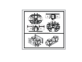
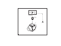
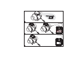
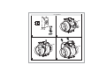
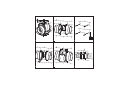
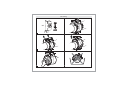
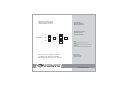
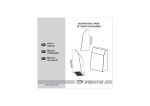
IN-LINE MIXED TYPE
FANS OF VENTS TT SILENT
SERIES
EN
User’s
manual
FR
Manuel
d'utilisation
ES
Manual
de usuario
www.vents-us.com
EN
READ AND SAVE THESE INSTRUCTIONS
WARNING!
TO REDUCE THE RISK OF FIRE, ELECTRIC SHOCK, INJURY TO PERSONS, READ THE INSTRUCTIONS
CAREFULLY
1. Use this unit only in the manner intended by the manufacturer. If you have questions, contact the manufacturer.
2. Before servicing or cleaning the unit, switch off the power at the service panel and lock it to prevent power
from being switched on accidentally. When the power can not be locked securely, fasten a prominent warning
device, such as tag, to the service panel.
3. Installation work and electrical wiring must be done by qualified person(s) in accordance with all applicable
codes and standards, include fire-rated construction codes and standards.
4. Sufficient air is needed for proper combustion and exhausting of gases through the flue (chimney) of fuel
burning equipment to prevent backdrafting. Follow the heating equipment manufacturer’s guideline and safety
standards, such as those published by the National Fire Protection Association (NFPA), and the American Society
for Heating, Refrigeration and Air Conditioning Engineers (ASHRAE), and the local code authorities.
5. When cutting or drilling into wall or ceiling, do not damage electrical wiring and other hidden utilities.
6. Fans with exhaust ducts must always be vented to the outdoors.
7. This unit may have sharp edges. Use caution to avoid being cut when installing and cleaning.
8. This unit must be grounded.
CAUTION!
1. For general ventilating use only. For use in non fire rated installations only.
Do not use exhaust hazardous or explosive materials and vapors.
2. For interior use only. Mount with the lowest moving parts at least 8 feet (2.5 meters) above the floor or grade level.
3. To avoid motor damage and noisy and/or unbalanced impeller, keep drywall spray, construction duct, etc. off power unit.
4. Before installation unit one must be convinced of absence of visible damages of impeller and housing. Inwardly
housing must not be parts, which can damage to blades of the impeller.
5. Please read specification label on product for further information and requirements.
6. Not for installation by children or any person who is unable to follow these safety guidelines.
7. Connect through switch built into fixed wiring. Gap between breaker contacts on all poles must
be not less than 1/8”.
8. Do not close or block unit inlets and outlets in order to allow optimal air passage. Do not sit or put objects on the unit.
9. Store fan in manufacturer’s packaging in ventilated room at temperatures between 41 and 104ºF and relative
humidity not more than 80%. The ambient air in a stockroom must not contain corrosion-provoking dust, acid or alkali
vapours.
The fans are in-line mixed type fans designed for
extract ventilation of rooms heated in winter time. Fans
are made of white plastic. Delivery set includes:
1. Fan - 1;
2. Screws with plugs - 4;
3. User’s manual;
4. Packing box.
An air duct at least 40 inches (1 meter) long should be
connected to an inlet flange in case of horizontal fan
mounting; a canopy should be installed on an inlet flange
in case of vertical mounting. Outlet flange should always
be connected to an air duct. Mounting is shown on
Fig. 7-16. Air motion must coincide with direction of i
ndicator on the fan case.
Fans are compatible with 4” (100 mm), 5” (125 mm),
6” (150 mm) diameter ducts.
Input: 120V AC 60Hz. Scheme of fan connection to the
power network is shown on Fig. 3. Fans are designed for
continuous operation without disconnection from network.
Protection rating from access to dangerous parts and
water penetration is IPX4. Fans can be operated at
ambient temperatures between +37 ° F and +107 ° F
(for the details, please, see the manufacturer's catalog).
- VENTS TT SILENT ÕÕÕ - the basic fan model, equipped
with an integrated speed switch and a power cord
with a plug. It is provided with the following operation
modes (see fig. 4):
“0”– turned off, the fan is not operating;
“I” – the fan is operating at minimum speed;
“II” – the fan is operating at maximum speed.
- VENTS TT SILENT ÕÕÕ S - the fan is equipped with a
high-powered motor;
- VENTS TT SILENT ÕÕÕ U(U1, U2) - the fan is equipped
with an integrated speed controller with electronic thermostat,
built into the fan's duct temperature sensor, and power cord
with plug (fig. 5);
Fan surfaces need to be cleaned of dirt and dust
regularly by using a soft, wet cloth and mild detergent
(Fig. 17-22).
Do not allow liquids to come in contact with the
electric motor. Wipe surfaces dry after cleaning.
Fan construction is constantly being improved, that is
why some models can differ slightly from those described
in this manual models.
- VENTS TT SILENT ÕÕÕ Un (U1n, U2n) - the fan is equipped
with an integrated speed controller with electronic thermostat,
remote temperature sensor fixed on 13 feet cable, and power
cord with plug (fig. 5);
- VENTS TT ÕÕÕ P - the fan is equipped with an integrated
smooth speed controller and power cord with plug (fig. 6).
Fans may be mounted either vertically or horizontally
(fig. 1). Fans may be used either separately or as part of
a set for parallel or in-line mounting (fig. 2). Parts that
come with connecting units are delivered separately.
Recycle at the end of unit's
service life.
Do not dispose of with other trash.
ELECTRONICS CONTROL LOGIC
VENTS TT SILENT___ U/U1/U2 fan (fig. 5) enable automatic
impeller speed (air flow) control depending on the air
temperature in the duct.
The "n" index models are equipped with a remote
temperature sensor on a 13 feet extension cable.
The terminal box cover incorporates two control knobs and two
LED light indicators:
- motor speed preset knob;
- electronic thermostat operation threshold knob;
- yellow LED light for electronic thermostat operating status
indication;
- green LED light for power supply indication.
To set the thermostat's operation threshold point rotate the
thermostat control knob clockwise to increase
or rotate counter-clockwise to decrease the thermostat's
operation threshold point.
To set the fan's motor speed (air capacity) rotate the speed
control knob in the same way.
The subsequent fan operation depends on the chosen
operating mode:
TT SILENT U Operating Mode
Set the minimum air flow required using the speed dial (i.e.
impeller speed under temperatures below the thermostat
operating threshold). On reaching the pre-set air
temperature the motor will switch to a higher (maximum)
speed. The fan will switch down as soon as
the duct temperature drops 2° below the pre-set thermostat
operating threshold. This prevents frequent fan speed
changing triggered by crossing the temperature threshold.
The above algorithm is used to precisely maintain the
desired temperature.
TT SILENT U1 Operating Mode
Set the minimum air flow required using the speed dial
(I.e. impeller speed under temperatures below the thermostat
operating threshold).
On reaching the pre-set air temperature the motor will switch to
a higher (maximum) speed and the delay timer will start the 5minute countdown. The motor reverts to the previous (low)
speed not earlier than 5 minutes after provided the duct air
temperature is lower than the thermostat preset.
The minimum switching cycle in this mode is 5 minutes.
TT SILENT U2 Operating Mode
Set the desired fan speed by turning the speed dial.
The fan stops as soon as the duct air temperature reaches
the pre-set thermostat operating threshold.
On exceeding the pre-set temperature the fan will switch to
the pre-defined speed until the duct temperature drops 2°
below the thermostat threshold.
The VENTS TT SILENT ___ P fan (fig. 6) is equipped with a
speed controller that enables the fan switching
on/off, smooth motor speed (air capacity) regulation within
the range of minimum to maximum motor speed.
WARRANTY
Production meets standard operating
requirements in the territory of the USA and Canada.
Manufacturer guarantees normal operation of the
unit for 60 months from the date of resale, subject to
the compliance with transport, storage, mounting
and operation rules.
If proof of sales date is absent, warranty period is
calculated from the production date.
In case of failure due to faulty equipment
warranty period, the consumer has the right to
exchange it.
The unit can be exchanged at the following
address:
Bodor Vents, LLC
11013 Kenwood Road Cincinnati, Ohio 45242
Phone: (513)348-3853
e-mail: [email protected]
Manufacturer is not responsible for damages
resulting from misuse of the unit or gross
mechanical alteration.
Owner of the unit must follow the guidelines set
forth in the manual.
Typical installation of the fan
min 1 diameter
min 3 diameter
1
Kits for parallel and in-line use fans
2
Connection of the fan and standard wall socket
HOUSE JUNCTION BOX
QF
AUTOMATIC
SWITCH
GREEN
GROUND
SCREW
120vAC, 60Hz
HOUSE POWER
STANDARD
WALL SOCKET
FAN
3
EARTH
GROUND
STANDARD
MIN
MAX
STOP
4
U/U1/U2
Un/U1n/U2n
Speed control
knob
Thermostat control
knob
5
P
Speed control
knob
min
6
max
Fan installation
QF
7
8
9
10
11
12
13
14
15
16
Fan cleaning
QF
17
18
19
20
21
22
ACCEPTANCE CERTIFICATE
CERTIFICAT D'ACCEPTATION
CERTIFICADO DE CALIDAD
Approval mark
Signe d'approbation
Marca de producción
Manufactured on (date):
Fabriqué le (date)
Fecha de producion
U
100
U1
TT SILENT
125
n
S
U2
150
P
Sold
(name of trading enterprise, stamp of store)
Vendu
(nom d'entreprise de commerce, cachet du magasin)
Vendido
(Nombre de empresa de comercial, timbro o sello)
The fan has been duly certified as serviceable.
Le ventilateur a été certifié comme utilisable.
Este ventilador está certificado para el uso normal.
Date of sale
Date de la vente
Fecha de venta
www.vents-us.com