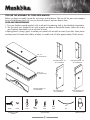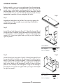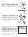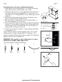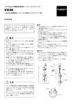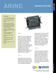
1
STEP 8
D
D
B
RIGHT SIDE PANEL 1PC
B
LEFT SIDE PANEL 1PC
D
B
B
STEP 5
D
TIPS FOR THE ASSEMBLY OF YOUR NEW MANTEL
Before you begin assembly, locate the instructions and hardware. Take out all the parts and compare
them to the diagrams below. Be sure you have all the parts and can identify them.
LEFT SIDE PANEL 1PC
CARE
AND MAINTENANCE
BASE 1PC
RIGHT SIDE PANEL 1PC
1. Dust your fireplace mantel regularly with a soft non-lint producing cloth or household dusting product.
2.You can clean your fireplace insert with a gentle non-abrasive household cleaner. Make sure to dry
your fireplace immediately with a soft cloth or towel.
LEFT SIDE PANEL 1PC
BASE 1PC
RIGHT SIDE PANEL 1PC
A helping hand is always good. Assemble your mantel with an adult assistant if possible. Some pieces
are heavy and will need to be held by a helper. Assembly time will take approximately 30-60 minutes.
F
G
F
A
G
A
AA
AA
F
F
E
STEP 7
RIGHT FRONT PANEL 1PC
E
AA
LEFT FRONT PANEL 1PC
CENTRAL HEADER 1PC
C
AA
AA
AA
21
STEP 4
LEFT SIDE PANEL 1PC
C
RIGHT FRONT PANEL 1PC
LEFT FRONT PANEL 1PC
2
UPPER FACING 1PC
LEFT FRONT
CENTRAL HEADER
1PCPANEL 1PC
RIGHT FRONT PANEL 1PC
FRONT BASE SUPPORTOR
TOP 1 PC
ZZ.2367BWLG.01
CENTRAL HEADER 1PC
STEP 1
BOTTOM SUPPORTER 1PC
2
LEFT FRONT PANEL 1 PC
ZZ.2367BWLG.04
UPPER FACING 1PC
1PC
1PCS
FLAT HEAD SCREW
(4*15mm)2PCS
BOTTOM SUPPORTER 1PC
RPRIGHT SUPPORTER 24PC
2PCS
2 PCS
HEAD SCREW
30mm)2PCS
ING LOCK 24PCS
FLAT HEAD SCREW
(4*25mm)2PCS
2PCS
TOP
BASE SUELF
SCREW
RGHTFLAT
SIDEHEAD
PANEL
1 PC
FLAT HEAD SCREW
ZZ.2367BWLG.07
(4*15mm)2PCS
(4*15mm)2PCS
FF
STEP 4
FLAT HEAD
SCREW
30mm
(4*25mm)2PCS
FLAT HEAD SCREW
ANTI-TIP DEVICE
RPRIGHT SUPPORTER 24PC
21
FRONT BASE SUPPORTOR
WING NUT
UPPER FACING 1PC
AA
EE
FLAT HEAD SCREW
(4*25mm)2PCS
1
21
EE CC
2 PCS
2
WASHER
15mm
WING NUT
RIGHT SUPPORTER
WINGNUT
& LOCK
FIG 24PC
5
FLAT HEAD SCREW
(4*30mm)2PCS
(4*30mm)2PCS
2PCS
2 PCS
ANCHOR
1 PC
2PCSPANEL
2PCSLEFT SIDE
2PCS
ZZ.2367BWLG.06
DD
FLAT HEAD SCREW
2 PCS
BB
AA
16 PCS
2PCS
2
NG LOCK 24PCS
16 PCS
5
2
CC
MOUNTING BRACKET
ANCHOR
BB
2
FLAT HEAD SCREW
MOUNTING BRACKET 2
2
GG
TOP
RPRIGHT SUPPORTER 24PC
2
12
CENTRAL HEADER 1 PC
ZZ.2367BWLG.03
SPRING LOCK 24PCS SPRING LOCK 24PCS2PCS
RPRIGHT SUPPORTER 24PC
TOP
FLAT HEAD SCREW
FLAT HEAD SCREW
CABLE
TIE SCREW
FLAT HEAD
BASE SUELF
11
AA
CC
BB
DD
CC
EE
DD
FFEE
BASE 1 PC
ZZ.2367BWLG.02
CABLEUP
TIESTAIN
TOUCH
21
TOP
RGHT FRONT PANEL 1 PC
ZZ.2367BWLG.05
BOTTOM SUPPORTER 1PC
BOTTOM SUPPORTER 1PC
1
OM SUPPORTER 1PC
1
BASE SUELF
EE CC
EE CC
1
BASE SUELF
FRONT BASE SUPPORTOR
FRONT BASE SUPPORTOR
TOUCH UP STAIN
2
GGFF
GG
2
W
UPPERHEADER
FACING 1PC
TRAL
1PC
W
NTITY
1
1
ANTITY
1
11
11
11
11
1
1
1
BASE 1PC
(4*15mm)2PCS
1PCS
1PCS
1 PC
1PC
1 PC
1PC
TOUCH UP PAINT
S
GET READY TO START
Before assembly, use scissors to unwrap the parts from the packaging.
WING NUT
AA may cut
DO NOT use a box cutter or exacto-knife as you
into the
mantel pieces inside the box and damage the finish. Check for the
hardware bag which is RED and located inside the packaging, taped
to the top box. Be sure you DO NOT discard any pieces. Use an
ANCHOR
BB
appropriate screwdriver to insert and BASE
tighten
all screws.
1PC
RIGHT SIDE PANEL 1PC
F
G
21
2
LEFT SIDE PANEL 1PC
Step 1
Step 1
2
KONG
Locate base A and place it on the floor. Do not putCCit up against
the
wall at this point in the assembly as you need to get in behind the
mantel during assembly.
FLAT HEAD SCREW
(4x35mm)
DD
E
Step 2
C
2
Step 2
A
RIGHT FRONT PANEL 1PC
LEFT FRONT PANEL 1PC
Locate left and right side panels B and C. Take left side panel B and
line up the hole in the block on left side panel B with
inHEAD
baseSCREW
FLAT
EE the hole
(4x25mm)
A. Once lined up insert and tighten 1 wing nut AA through
lock
G
WING NUT
washer GG. Do not over tighten and strip wingAAnut AA. Repeat
for
right side panel C.
FF
QUANTITY
DESCRIPTION
UPPER FACING 1PC
BASE 1PC
1
1
1
1
1
1
1
BASE
F
FT SIDE PANEL EXTERIOR
GHT SIDE PANEL EXTERIOR
LEFT FRONT PANEL
RIGHT FRONT PANEL
CENTRAL HEADER
TOP
1
ANCHOR
2
BOTTOM
SUPPORTER
1PC
LEFT
SIDE PANEL
1PC
AA Wingnut
x2
21 Washer
LOCK WASHER GG Lock
HH
C
21
Used
TOUCH UP STAINHardware
1
2
KONG
CC
BASE SUELF
2
CABLE TIE
FRONT BASE
RIGHTSUPPORTOR
SIDE PANEL 1PC
GG
E
Step 3
BB
CENTRAL HEADER 1PC
TOPHEAD SCREW
FLAT
(4x35mm)
DD
2
x2
RPRIGHT SUPPORTER 24PC
Step 3
A
RIGHTD
FRONT
LEFT FRONT
CENTRAL
FIG 3right front panels
FIG 5 HEADER 1PC
Locate left and
andPANEL
E. 1PC
Take left front panel
DPANEL
and1PC
line up the hole in the block on left front panel D with the hole in
2
FLAT HEAD SCREW
EE
base A. Once lined up insert and tighten 1 wing nut AA through
lock
(4x25mm)
washer GG. Do not over tighten and strip wing nut AA. Line up the 2
HH
holes in the 2 AA
blocks
on left side panel B with the 2 holes in left front
panel D. Once lined up insert
and
tighten
AA through 2
FLAT HEAD SCREW
2PCS
2PCS
SPRING
LOCK
24PCS 2 wing nuts
(4*15mm)2PCS
lock washers GG. Do not over tighten and strip wing
nuts AA.
Repeat
CABLE TIE
1
FF
for right QUANTITY
front panel E.
DESCRIPTION
UPPER FACING 1PC
BOTTOM SUPPORTER 1PC
FRONT BASE SUPPORTOR KONG
BASE
1
FT SIDE PANEL EXTERIOR
1
FLAT HEAD
GHT SIDE PANEL EXTERIOR
1
SCREW
LEFT FRONT PANEL
Used
GG
TOUCH UP STAINHardware
1
1
RIGHT FRONT PANEL
1
AA Wingnut
x6
CENTRAL HEADER
1
TOP
1
1PCS
FLAT
FLAT HEAD SCREW
AA
x6 HEAD SCREW
WING NUT
EE CC
E
F
C
A
B
(4*30mm)2PCS
HH
LOCK WASHER
x6
BASE SUELF
CCGG KONG
21 Washer
Lock
HH(4*25mm)2PCS LOCK WASHER
TOP
2
EE
1PC
xx16
RPRIGHT SUPPORTER 24PC
FLAT HEAD SCREW
x2
(4*15mm)
FLAT HEAD SCREW
(4x35mm)
DD
E
Step 4
C
2
Step 4
A
1PC
LEFT FRONT PANEL 1PC
Locate central header F. Line RIGHT
up FRONT
the PANEL
2 holes
on the bottom
central
header F with the wood dowels on each of theEEleft and right
frontSCREW
FLAT HEAD
G
panels (D and E). Press down until flush. Line up the 4 holes WING
in NUT
central
(4x25mm)
AA
header F with the 4 holes in the already built assembly
(2 on each
of the left and right side panels B and C). Once lined up insert and
tighten 4 wing nuts AA through 4 lock washers GG. Do not over
tighten and strip the wing nuts AA.
CABLE TIE
FF
QUANTITY
DESCRIPTION
F
BASE 1PC
UPPER FACING 1PC
1
1
1
1
1
1
1
BASE
FT SIDE PANEL EXTERIOR
GHT SIDE PANEL EXTERIOR
LEFT FRONT PANEL
RIGHT FRONT PANEL
CENTRAL HEADER
TOP
ANCHOR
BB
RIGHT SIDE PANEL 1PC
FRONT BASE SUPPORTOR
CENTRAL HEADER 1PC
2
21
12
LEFT SIDE PANEL 1PC
BOTTOM SUPPORTER 1PC
KONG
TOUCH UP STAINHardware
12 Used
GG
CC
AA Wingnut
21 Washer
LOCK WASHER GG Lock
HH
DD
E
C
Step
5
A
x4
FLAT HEAD SCREW
TOP
(4x35mm)
BASE SUELF
RIGHT FRONT PANEL 1PC
2
x4
RPRIGHT SUPPORTER 24PC
Step 5
LEFT FRONT PANEL 1PC
CENTRAL HEADER 1PC
Get your assistant
and locate the top of your mantel. This top is very
FIG 3
FIG 5
2
FLATplace.
HEAD SCREW
heavy. It will take 2 people to lift and position EEthe top into
Place top G onto the mantel assembly already built with (4x25mm)
the front
and sides over the assembly. Make sure the wood dowel on the top
AA HH
of central header
F lines up with the hole in top G. Press down until
flush. From underneath, lineSPRING
up 4LOCK
holes
in the mantel top
FLAT HEAD SCREW
2PCS with 4 holes
2PCS
24PCS
(4*15mm)2PCS
CABLE
1
FF
in the mantel assembly (2 each in the left and right side panels
B TIE
and
QUANTITY
DESCRIPTION
C). Once lined up insert and tighten
4 1PC
wing nuts AA FRONT
through
4 lock
UPPER FACING
BOTTOM SUPPORTER 1PC
BASE SUPPORTOR
BASE
1
washers
GG.
Do
not
over
tighten
and
strip
the
wing
nuts
AA.
KONG
FT SIDE PANEL EXTERIOR
1
GHT SIDE PANEL EXTERIOR
1
FLAT HEAD
LEFT FRONT PANEL
Hardware
Used
SCREW
GG
TOUCH UP STAIN
1
1
RIGHT FRONT PANEL
1
AA Wingnut
x4
CENTRAL HEADER
1
TOP
1
EE CC
E
F
C
B
A
AA
FLAT
x6 HEAD SCREW
(4*30mm)2PCS
WING NUT
Step 6
21 Washer
Lock
LOCK WASHER GG 1PCS
HH
FLAT HEAD SCREW
CC
KONG
(4*25mm)2PCS
EE
x6
LOCK WASHER
x4
x1
RPRIGHT SUPPORTER 24PC
TOP
BASE SUELF
HH
1PC
Take your electric firebox out of its packaging and position it between
FIGthe
3
the 2 legs of
mantel. Once you are close to the wall, plug the
FIG 4
firebox into the nearest outlet.
FLAT HEAD SCREW
(4*15mm)
Step 6
x2
FIG 5
FIG 6
The firebox comes
with 3 metal brackets and 10 black screws. These
AA HH
AA brackets must be attached to all 3 sides of the firebox and 2
metal
2PCS
LOCKfirebox
24PCS does not 2PCS
HH of the mantel to ensureSPRING
sides
that your
move around as
you use it. All 3 trims attach to the firebox by inserting and tightening
AA
2 screws. Both the left andHH
right side trim attach to the mantel front by
KONG
inserting and tightening 2 screws
EE CC
E
G
FLAT HEAD SCREW
2 IN
(4*15mm)2PCS
F
F
C
D
B
A
C
A
E
The top trim does not attach to the mantel, just the firebox. If you
have any questions about the firebox please reference the installation
instructions that come with the firebox.
AA
AA
WING NUT
WING NUT
FLAT
x6 HEAD SCREW
x5
(4*30mm)2PCS
FLAT HEAD SCREW
(4*25mm)2PCS
3
FLAT HEAD
SCREW
CC
1PCS
KONG
FLAT HEAD SCREW
1PC
x1
AA
E
AA
D
G
B
C
C
C
C
A
E
PART
F
D
QUANTITY
DESCRIPTION
BASE SUELF
Anti-tipping device (instructions included with hardware)
1. Attach one of the mounting brackets (CC) securely to the back
edge of the furniture. Use the shorter screws (DD).
LEFT
PANEL 1PCwhereRIGHT
FRONT PANEL 1PC
LEFT
FRONT
PANEL
1PC
CENTRAL
CENTRAL
1PC
2.FRONT
Determine
furniture
is to beHEADER
placed
and
mark
location
on HEADER1 1PC
A
B
1
the wall for the other mounting bracket (CC) screw holes.
You
C
1
D
1
may need to use 2 wall plugs (BB) if you are attaching EFto drywall 11
G
1
or p
laster.
3. Position the bracket over the holes and use the longer screws
(EE) to securely attach the bracket to wall.
4. Place the furniture so the bracket (CC) on the back edge is in
UPPER FACING 1PC
BOTTOM SUPPORTER
1PC
FRONT BASE SUPPORTOR
Hardware
Used
line with the bracket (CC) on the wall.
5. Place an end of the nylon restraint strap (FF) down through each
DD 5/8” Screw
bracket (CC). Bring both ends
together
and
slide
the
end
of
the
EE 1-3/8” Screw
BOTTOM SUPPORTER 1PC
FRONT BASE SUPPORTOR
strap through the slot in the other end until snug. Pull down on
CC Mounting Bracket
the end until it snap locks into the slot.
BB Anchor
6. Check to make sure the strap (FF) is securely laced and locked
RPRIGHT SUPPORTER 24PC
to the brackets (CC).
TOP
BASE SUELF
Young children may be injured by tipping furniture. The use of a
Wall
tipping restraint is highly recommended. This hardware,
when
LOCK
properly installed, could provide protection against the unexpected
Mantel
tipping of furniture due to improper use.
A
Step 7
AA
FLAT HEAD SCREW
(4*30mm)2PCS
AA
F
SPRING LOCK 24PCS
STEP 7
B
EEE CC
CC
E
Step 7
STEP 1
EE CC
MEF2362E
B
BASE
LEFT SIDE PANEL EXTERIOR
RIGHT SIDE PANEL EXTERIOR
BASE 1PC
LEFT FRONT PANEL
RIGHT SIDE PANEL 1PC
LEFT SIDE PANEL 1PC
E
RIGHT FRONT PANEL
CENTRAL SHELF
STEP 7
ST
AA
x2
BOTTOM SUPPORTER 1PC
F
CENTRAL HEADER 1PC
1PCS
FLAT HEAD SCREW
2 PCS
(4*15mm)2PCS
FLAT HEAD SCREW
(4*30mm)2PCS
1 PC
1PC
FLAT HEAD SCREW
(4*25mm)2PCS
Wall
G
D
C
A
E
FF Nylon Strap
FLAT HEAD SCREW
30mm
(4*25mm)2PCS
FLAT HEAD SCREW
(4*15mm)2PCS
1PCS
ELOCK
x1
1PC
C
BB
BASE 1PC
5
RIGHT SIDE PANEL 1PC
FLAT HEAD SCREW
(4*25mm)2PCS
2PCS
Hardware Used
STEP 2
STEP 1
F
LEFT SIDE PANEL 1PC
FLAT HEAD SCREW
(4*30mm)2PCS
2PCS
SPRING LOCK 24PCS
FF
BB
LEFT FRONT PANEL 1PC
C
A
AA
CC
GHT FRONT PANEL 1PC
STEP 5
2PCS
FRONT BASE SUPPORTOR
2 PCS
AA
PPER FACING 1PC
1PC
STEP 4
1PCS
RPRIGHT SUPPORTER 24PC
2PCS
TOP
SPRING LOCK 24PCS
BASE SUELF
A
2121
15mm
FLAT HEAD SCREW
(4*15mm)2PCS FF
22
EE
BB
G
D
E
FLAT HEAD SCREW
STEP 4
Wall
RPRIGHT SUPPORTER 24PC
DD
BB
STEP
CC
STEP 7
1PCS
RPRIGHT SUPPORTER 24PC
DD
FLAT HEAD SCREW
(4*15mm)2PCS
1PC
21
CC
B
CC
(4*30mm)2PCS
2PCS
2 PCS
BOTTOM SUPPORTER 1PC
E
TOP
21
2
2
2
1
AA
D
CC
FRONT BASE SUPPORTOR
BASE SUELF
RPRIGHT SUPPORTER 24PC
AA
BB
x2
C
A
UPPER FACING 1PC
22
FLAT HEAD SCREW
(4*15mm)2PCS
2PCS
FLAT HEAD SCREW
(4*15mm)2PCS
x2
2PCS
A
1PCS
WING NUT
WING NUT
ANCHOR
FLAT HEAD SCREW
1
11
MOUNTING BRACKET 2
2
ANCHOR
2
FLAT HEAD SCREW
MOUNTING BRACKET 2
2
FLAT HEAD SCREW
CABLE TIE
FLAT HEAD SCREW
TOUCH
CABLEUP
TIESTAIN
TOUCH UP STAIN
BB
BASE SUELF
AA
G2LOCK
24PCS
2
D
WARNING: This product is only a deterrent. It is not a
2PCS
2PCS
SPRING LOCK 24PCS
substitute for proper
adult supervision.
One anti-tip device includes the following:
T HEAD SCREW
25mm)2PCS
F
C
BB
TOP
CENTRAL HEADER 1PC
B
C
A
x2
LEFT FRONT PANEL 1PC
2PCS
AA
RIGHT FRONT PANEL 1PC
22
B
E
2 PCS
11
1PC
1PCS
AA
BB
AA
CC
BB
DD
CC
EE
DD
FF
EE
GGFF
GG
C
E
2PCS
2 IN
AA
D
A
DD
FLAT HEAD SCREW
(4*25mm)2PCS
AA
F
B
TOP
D
5
2PCS
AA
AA
1
G
AD1SCREW
m)2PCS
FLAT HEAD SCREW
(4*25mm)2PCS
AA
C
A
TOP
1PC
A
G
F
4
WARRANTY
Greenway Home Products is pleased to offer in-home warranty repairs. Please refer to your Firebox Use and Care Guide for warranty
information on your Firebox.
DO NOT RETURN THIS PRODUCT TO THE STORE:
Please contact Customer Service at: 1-866-253-0447
Monday to Thursday from 8:30AM to 5:00PM (EST), Friday from 8:30AM to 4:00PM (EST)
Web: www.greenwayhp.com
Email: [email protected]
Canada:400 Southgate Dr., Guelph, Ontario, Canada, N1G 4P5
USA: 1270 Flagship Dr., Perrysburg, Ohio, USA, 43551
Limited Warranty Definitions:
Greenway Home Products: (Greenway)Manufacturer.
Mantel: Mantel manufactured by Greenway Home Products.
Purchaser: Purchaser of the Mantel
Distributor: Facility authorized to sell Greenway Home Products.
Warranty Card Greenway Home Products Limited Warranty Registration Card identifying the Purchaser and product model.
Greenway Limited Warranty:
Greenway warrants to the Purchaser that the Mantel is free from defects in material and workmanship, under normal use and service, for
1 year (1 year limited parts) from the date of purchase.
All warranty repairs must be preauthorized by Greenway Home Products. Greenway will, at its’ option, replace or repair free of charge
any defective part, which the Purchaser shall notify their Distributor or Greenway Home Products within the warranty period. The obligation
of Greenway Home Products under this warranty, is expressly limited to such replacement or repairs.
The provisions of this limited warranty shall not apply to the following:
1. Accidents.
2. Unauthorized repairs or alterations.
3.Normal maintenance.
4. Changes made to other units manufactured after this mantel was manufactured.
5. Incidental damages caused by failure of the mantel such as inconvenience or loss of use.
6. Improper installation.
The provisions of this limited warranty shall not apply to deterioration due to wear and exposure beyond the following limitations:
1. For 180 days from the date of purchase for exterior finished surfaces.
Due to the properties of natural wood, Greenway Home Products makes no warranty against mineraling of wood components.
Greenway Limited Warranty is void unless the following conditions are adhered to:
1. Warranty registration must be completed and returned to a Greenway Home Products.
2. All warranty repairs must be preauthorized by a Greenway repair facility.
3. Greenway reserves the right to inspect defective parts that have been replaced under warranty. Dealer is expected to hold
defective parts for 60 days.
4. Only parts and accessories and other material, available through Greenway Home Products are to be used in the performance
of warranty service.
5. Purchasers are responsible for presenting/notifying their Distributor as soon a problem exists. The warranty repairs should be
completed in a reasonable amount of time from the date of authorization. Not to exceed 30 days past notification.
This limited warranty is expressly in lieu of any other expressed or implied warranty, including any implied warranty or
merchantability or fitness for a particular purpose and of any obligations or liabilities on Greenway Home Products which
neither assumes nor authorizes any other person to assume for it any other liability in connection with the Mantel
manufactured by it.
The warranty is null and void if used in commercial or industrial applications.
5