1
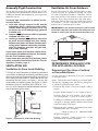
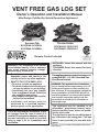
VENT FREE GAS LOG SET
Owner’s Operation and Installation Manual
Also Design Certified As Vented Decorative Appliances
Savanna Oak
SCVFR18N SCVFR18L
SCVFR24N SCVFR24L
Premier Estate
PEVFR18NG PEVFR18LP
PEVFR24NG PEVFR24LP
Remote Control Included
WARNING: If the information in this manual
is not followed exactly, a fire or explosion
may result causing property damage,
personal injury, or loss of life.
— Do not store or use gasoline or other
flammable vapors and liquids in the
vicinity of this or any other appliance.
— WHAT TO DO IF YOU SMELL GAS
• Do not try to light any appliance.
• Do not touch any electrical switch; do
not use any phone in your building.
• Immediately call your gas supplier
from a neighbor’s phone. Follow the
gas supplier’s instructions.
• If you cannot reach your gas supplier,
call the fire department.
— Installation and service must be
performed by a qualified installer,
service agency, or the gas supplier.
This is an unvented gas-fired heater. It uses
air (oxygen) from the room in which it is
installed. Provisions for adequate combustion and ventilation air must be provided.
Refer to page 4, Air for Combustion and
Ventilation.
ANSI Z21.11.2 - 2011
Unvented Heaters
ANSI Z21.60 - 2004
Vented Decorative
INSTALLER: Leave this manual with the
appliance.
CONSUMER: Retain this manual for future
reference.
This appliance has been tested and approved
under ANSI Z21.11.2–2011 Unvented GasFired Room Heaters.
WARNING: This appliance is for installation
only in a solid fuel burning masonry or UL127
factory-built fireplace or listed ventless firebox enclosure. It has been design certified for
these installations. EXCEPTION: DO NOT install this appliance in a factory-built fireplace
that includes instruction stating it has not
been tested or should not be used with unvented gas logs.
This appliance may be installed in an
aftermarket,* permanently located, manufactured (mobile) home, where not prohibited by local codes.
This appliance is only for use with the type of
gas indicated on the rating plate. This appliance is not convertible for use with other
gases.
* Aftermarket: Completion of sale, not for purpose of resale, from
the manufacturer
TABLE OF CONTENTS
Safety Information ........................................................ 2
Local Codes .................................................................. 3
Unpacking ..................................................................... 4
Product Features............................................................ 4
Qualified Installation Agency ....................................... 4
Air For Combustion and Ventilation ............................ 4
Installation..................................................................... 7
Operating Log Set ....................................................... 15
Inspecting Burners ...................................................... 18
Cleaning and Maintenance.......................................... 18
Troubleshooting .......................................................... 19
Specifications .............................................................. 23
Parts List and Illustrated Parts Breakdown ................. 22
Warranty Information .................................. Back Cover
SAFETY INFORMATION
You must operate this heater with the fireplace screen in place. Make sure the fireplace
screen is in place before funning this appliance.
Unless other provisions are made for combustion air, the screens shall have an opening
or openings for introduction of combustion
air into the fireplace
If this appliance is installed in a fireplace that
has glass doors, the doors must be left open
when the appliance is in use.
WARNING: Improper installation, adjustment, alteration, service, or maintenance
can cause injury or property damage. Refer
to this manual for correct installation and
operational procedures. For assistance or
additional information consult a qualified
installer, service agency, or the gas supplier.
WARNING:This product contains and/or
generates chemicals known to the state of
California to cause cancer or birth defects
or other reproductive harm.
2
DANGER: Carbon monoxide poisoning
may lead to death!
Carbon Monoxide Poisoning: Early signs of carbon
monoxide poisoning resemble the flu, with headaches, dizziness, and/or nausea. If you have these signs, heater may
not be working properly. Get fresh air at once! Have
heater serviced. Some people–pregnant women, persons
with heart or lung disease, anemia, those under the influence of alcohol, those at high altitudes–are more affected
by carbon monoxide than others.
Propane/LP Gas: Propane/LP gas is odorless. An odormaking agent is added to the gas. The odor helps you detect
a gas leak. However, the odor added to the gas can fade.
Gas may be present even though no odor exists.
Make certain you read and understand all warnings. Keep
this manual for reference. It is your guide to safe and proper
operation of this appliance.
WARNING: Any change to this heater
or its controls can be dangerous.
WARNING: Do not use a blower insert,
heat exchanger insert, or other accessory
not approved for use with this appliance.
WARNING: Do not allow fans to blow
directly into the appliance. Avoid any drafts
that alter burner flame patterns. Ceiling
fans can create drafts that alter burner
flame patterns. Altered burner patterns can
cause sooting.
Due to high temperatures, the appliance
should be located out of traffic and away
from furniture and draperies.
Do not place clothing or other flammable
material on or near the appliance. Never
place any objects on the heater.
Fireplace front and screen become very
hot when running appliance. Keep children and adults away from hot surfaces to
avoid burns or clothing ignition. Logs will
remain hot for a time after shutdown. Allow
surfaces to cool before touching.
Carefully supervise young children when
they are in the room with fireplace.
SAFETY
INFORMATION
CONTINUED
Keep the appliance area clear and free from
combustible materials, gasoline, and other
flammable vapors and liquids.
1. This appliance is only for use with the type of gas
indicated on the rating plate. This appliance is not
convertible for use with other gases.
2. Do not place propane/LP supply tank(s) inside any
structure. Locate propane/LP supply tank(s) outdoors
(propane/LP units only).
3. If you smell gas
• shut off gas supply
• do not try to light any appliance
• do not touch any electrical switch; do not use any
phone in your building
• immediately call your gas supplier from a neighbor’s
phone. Follow the gas supplier’s instructions
• if you cannot reach your gas supplier, call the
department
4. This appliance shall not be installed in a bedroom or
bathroom.
5. Do not use this appliance as a wood-burning fireplace.
Use only the logs provided with the appliance.
6. Do not add extra logs or ornaments such as pine cones,
vermiculite or rock wool. Using these added items can
cause sooting and poor combustion. Do not add lava
rock around base. Rock and debris could fall into the
control area of heater.
7. This appliance is designed to be smokeless. If logs ever
appear to smoke, turn off appliance and call a qualified
service person. Note: During initial operation, slight
smoking could occur due to log curing and fireplace
burning manufacturing residues.
8. To prevent the creation of soot, follow the instructions
in Cleaning and Maintenance section.
Keep the appliance area clear and free from
combustible materials, gasoline and other
flammable vapors and liquids.
9. Before using furniture polish, wax, carpet cleaner, or
similar products, turn heater off. If heated, the vapors
from these products may create a white powder residue
within burner box or on adjacent walls or furniture.
10. This appliance needs fresh air ventilation to run properly. This appliance has an Oxygen Depletion Sensing
(ODS) safety shutoff system. The ODS shuts down the
fireplace if not enough fresh air is available. See Air
for Combustion and Ventilation, pages 4 through 6.
If appliance keeps shutting off, see Troubleshooting,
pages 17 through 20.
11. Do not run appliance
• where flammable liquids or vapors are used or
stored
• under dusty conditions
12. Do not use this appliance to cook food or burn paper
or other objects.
13. Never place any objects in the heater or on logs.
14. Do not use appliance if any part has been exposed to
or under water. Immediately call a qualified service
technician to inspect the appliance and to replace any
part of the control system and any gas control which
has been under water.
15. Turn appliance off and let cool before servicing. Only
a qualified service person should service and repair
appliance.
16. Operating appliance above elevations of 4,500 feet
could cause pilot outage.
17. To prevent performance problems, do not use propane/
LP fuel tanks of less than 100 lbs. capacity.
18. Provide adequate clearances around air openings.
LOCAL CODES
Install and use appliance with care. Follow all local codes.
In the absence of local codes, use the latest edition of The
National Fuel Gas Code ANSI Z223.1/NFPA 54*.
*Available from:
American National Standards Institute, Inc.
1430 Broadway
New York, NY 10018
National Fire Protection Association, Inc.
Batterymarch Park
Quincy, MA 02269
State of Massachusetts: The installation must
be made by a licensed plumber or gas fitter in the
Commonwealth of Massachusetts.
Sellers of unvented propane or natural gas-fired
supplemental room heaters shall provide to each
purchaser a copy of 527 CMR 30 upon sale of
the unit.
Vent-free gas products are prohibited for bedroom
and bathroom installation in the Commonwealth of
Massachusetts.
3
UNPACKING
1. Remove the carton and log wrap.
2. Remove all protective packaging applied to heater for
shipment.
3. Make sure your logset includes one hardware packet.
4. Check heater for any shipping damage. If h eater is
damaged, call SHM International at (800) 229-5647
for replacement parts before returning to dealer.
PRODUCT FEATURES
SAFETY PILOT
This heater has a pilot with an Oxygen Depletion Sensing
(ODS) safety shutoff system. The ODS/pilot is a required
feature for vent-free room heaters. The ODS/pilot shuts off
the heater if there is not enough fresh air.
PIEZO IGNITION SYSTEM
This heater has a piezo ignitor. This system requires no
matches, batteries or other sources to light heater.
THERMOSTATIC HEAT CONTROL
Thermostat-controlled models have a thermostat sensing
bulb and a control valve. The thermostat will automatically
modulate the heat output to maintain a consistent room
temperature. This results in greater heater comfort. This
can also result in lower gas bills.
QUALIFIED
INSTALLATION AGENCY
Installation and replacement of gas piping, gas utilization equipment or accessories and repair and servicing of
equipment shall be performed only by a qualified agency.
The term “qualified agency” means any individual, firm,
corporation, or company that either in person or through a
representative is engaged in and is responsible for:
A. Installation, testing or replacements of gas piping or
B. Connection, installation, testing, repair or servicing
of equipment that is experienced in such work; that
is familiar with all precautions required; and that has
complied with all requirement of the authority having
jurisdiction.
4
AIR FOR COMBUSTION
AND VENTILATION
WARNING: This heater shall not be
installed in a room or space unless the
required volume of indoor combustion air
is provided by the method described in
the National Fuel Gas Code, ANSI Z223.1/
NFPA 54, the International Fuel Gas Code,
or applicable local codes.
Read the following instructions to insure
proper fresh air for this and other fuelburning appliances in your home.
Today’s homes are built more energy efficient than ever.New
materials, increased insulation, and new construction methods
help reduce heat loss in homes. Home owners weather strip
and caulk around windows and doors to keep the cold air out
and the warm air in. During heating months, home owners
want their homes as airtight as possible.
While it is good to make your home energy efficient, your
home needs to breathe. Fresh air must enter your home. All
fuel-burning appliances need fresh air for proper combustion and ventilation.
Exhaust fans, fireplaces, clothes dryers, and fuel burning appliances draw air from the house to operate. You must provide
adequate fresh air for these appliances. This will insure proper
venting of vented fuel-burning appliances.
PROVIDING ADEQUATE
VENTILATION
The following are excerpts from National Fuel Gas Code
ANSI Z223.1/NFPA 54,Section 5.3, Air for Combustion
and Ventilation.
All spaces in homes fall into one of the following
ventilation classifications:
1. Unusually Tight Construction
2. Unconfined Space
The information on pages 4 through 6 will help you classify
your space and provide adequate ventilation.
Unusually Tight Construction
Ventilation Air From Outdoors
The air that leaks around doors and windows may provide
enough fresh air for combustion and ventilation. However, in
buildings of unusually tight construction, you must provide
additional fresh air.
Provide extra fresh air by using ventilation grills or ducts.
You must provide two permanent openings: one within
12" of the ceiling and one within 12" of the floor. Connect
these items directly to the outdoors or spaces open to the
outdoors. These spaces include attics and crawl spaces.
Follow the National Fuel Gas Code ANSI Z223.1/NFPA
54, Section 5.3, Air for Combustion and Ventilation for
required size of ventilation grills or ducts.
Unusually tight construction is defined as construction where:
a. walls and ceilings exposed to the outside
atmosphere have a continuous water vapor
retarder with a rating of one perm (6 x 10-11 kg
per pa-sec-m2) or less with openings gasketed
or sealed and
b. weather stripping has been added on openable
windows and doors and
c. caulking or sealants are applied to areas such
as joints around window and door frames,
between sole plates and floors, between wallceiling joints, between wall panels, at penetra
tions for plumbing, electrical, and gas lines,
and at other openings.
If your home meets all of the three criteria above,
you must provide additional fresh air. See Ventilation Air From Outdoors, page 5.
If your home does not meet all of the three criteria
above, proceed to Determining Fresh-Air Flow for
Appliance Location, page 6.
VENTILATION AIR
Ventilation Air From Inside Building
This fresh air would come from an adjoining unconfined
space. When ventilating to an adjoining unconfined space,
you must provide two permanent openings: one within 12"
of the ceiling and one within 12" of the floor on the wall
connecting the two spaces (see Figure 1). You can also
remove door into adjoining room (see Figure 1). Follow
the National Fuel Gas Code ANSI Z223.1/NFPA 54, Section 5.3, Air for Combustion and Ventilationfor required
size of ventilation grills or ducts.
12"
Ventilation
Grills
Into Adjoining
Room,
Option 1
Ventilation Grills
Into Adjoining Room,
Option 2
Or
Remove
Door into
Adjoining
Room,
Option
3
12"
Figure 1 - Ventilation Air from Inside Building
IMPORTANT: Do not provide openings for inlet or outlet
air into attic if attic has a thermostat-controlled power vent.
Heated air entering the attic will activate the power vent.
Outlet
Air
Outlet
Air
Ventilated
Attic
To Attic
To
Crawl
Space
Inlet
Air
Inlet Air
Ventilated
Crawl Space
Figure 2 - Ventilation Air from Outdoors
DETERMINING FRESH-AIR FLOW
FOR APPLIANCE LOCATION
Determining if You Have a Confined
or Unconfined Space
Use this work sheet to determine if you have a confined
or unconfined space.
Space: Includes the room in which you will install appliance plus any adjoining rooms with doorless passageways
or ventilation grills between the rooms.
1. Determine the volume of the space (length x width x
height).
Length x Width x Height = cu. ft. (volume of space)
Example: Space size 22 ft. (length) x 18 ft. (width) x
8 ft. (ceiling height) = 3168 cu. ft. (volume of space)
If additional ventilation to adjoining room is supplied
with grills or openings, add the volume of these rooms
to the total volume of the space.
2. Multiply the space volume by 20 to determine the maximum Btu/Hr the space can support.
_______ (volume of space) x 20 = (Maximum Btu/Hr
the space can support)
Example: 3168 cu. ft. (volume of space) x 20 = 63,360
(maximum Btu/Hr the space can support)
5
AIR FOR COMBUSTION
AND VENTILATION
CONTINUED
3. Add the Btu/Hr of all fuel burning
space.
Vent-free log set _______________
Gas water heater* ______________
Gas furnace___________________
Vented gas heater ______________
Gas fireplace logs ______________
Other gas appliances* + ________
Total
= ________
appliances in the
Btu/Hr
Btu/Hr
Btu/Hr
Btu/Hr
Btu/Hr
Btu/Hr
Btu/Hr
* Do not include direct-vent gas appliances. Direct-vent
draws combustion air from the outdoors and vents to
the outdoors.
Example:
39,000 Btu/Hr
Vent-free log set ______________
40,000 Btu/Hr
Gas water heater* _____________
79,000 Btu/Hr
Total
= ________
4. Compare the maximum Btu/Hr the space can support with
the actual amount of Btu/Hr used.
____ Btu/Hr (max. the space can support)
____ Btu/Hr (actual amt. of Btu/Hr used)
Example: 63,300 Btu/Hr (maximum the space can support)
73,000 Btu/Hr (actual amount of Btu/Hr used)
The space in the above example is a confined space because
the actual Btu/Hr used is more than the maximum Btu/Hr
the space can support. You must provide additional fresh
air. Your options are as follows:
A. Rework work sheet, adding the space of an adjoining room.
If the extra space provides an unconfined space, remove
door to adjoining room or add ventilation grills between
rooms. See Ventilation Air from Inside Building,page 5.
B. Vent room directly to the outdoors. See Ventilation Air
from Outdoors, page 5.
WARNING: If the area in which the
heater may be operated does not meet the
required volume for indoor combustion
air, combustion and ventilation air shall be
provided by one of the methods described
in the National Fuel Gas Code, ANSI Z223.1/
NFPA 54, the International Fuel Gas Code,
or applicable local codes.
Note: When used as a vented heater, appliance must be
installed only in a solid-fuel burning fireplace with a
working flue and constructed of noncombustible material.
VENTED OPERATION
You may also use this heater as a vented product. There are.
three reasons for operating your heater in the vented mode.
1.
2.
The fireplace does not meet the clearance to combustibles requirements for vent-free operation.
State or local codes do not permit vent-free operation.
3.
You prefer vented operation.
If reasons number 1 or 2 above apply to you, you must permanently open chimney flue damper. You must install the
damper clamp. This will insure vented operation (see Figu r e 10). The damper clamp will keep damper open.
See chart below for minimum permanent flue opening
you must provide. Attach damper clamp so the minimum permanentflue opening will be maintained at all times.
Area of Various Standard
Round Flues
Diameter (ins.)
Area (sq. ins.)
5"
6"
7"
8"
20 sq. inches
29 sq. inches
39 sq. inches
51 sq. inches
Chimney
Minimum Permanent
Height (ft.) Flue Opening (sq. ins.)
6' to 15'
15' to 30'
39 sq. inches
29 sq. inches
C. Install a lower Btu/Hr appliance, if lower Btu/Hr size
makes room unconfined.
If the actual Btu/Hr used is less than the maximum Btu/Hr
the space can support, the space is an unconfined space.
You will need no additional fresh air ventilation.
6
Follow instructions INSTALLING DAMPER Clamp on
page
INSTALLATION
WARNING: Before installing in a solidfuel-burning fireplace, the chimney flue
and firebox must be cleaned of soot, creosote, ashes, and loose paint by a qualified
chimney cleaner.
NOTICE: This appliance is intended for
supplemental heating. Use this heater
along with your primary heating system.
Do not install this heater as your primary
heat source. If you have a central heating
system, you may run system’s circulating
blower while using heater. This will help
circulate the heat throughout the house. In
the event of a power outage, you can use
this heater as your primary heat source.
WARNING: A qualified service person must
install appliance. Follow all local codes.
•
•
•
•
•
WARNING: Never install the appliance
in a recreational vehicle
where curtains, furniture, clothing, or
other flammable objects are less than
36 inches (91.5 cm) from the front, top,
or sides of the appliance
in a wood-burning stove
areas
in high
in windy or drafty areas
WARNING: Never install in a bedroom
or bathroom. Any heating product with a
Btu/Hr rating over 10,000 cannot be used
in a bedroom. Any heating product with a
Btu/Hr rating over 6,000 cannot be used
in a bathroom.
CAUTION: This appliance creates warm
air currents. These currents move heat to
wall surfaces next to appliance. Installing
appliance next to vinyl or cloth wall coverings or operating appliance where impurities
(such as tobacco smoke, aromatic candles,
cleaning fluids, oil or kerosene lamps, etc.)
in the air exist, may discolor walls.
IMPORTANT: Vent-free heaters add moisture to the air.
Although this is beneficial, installing appliance in rooms
without enough ventilation air may cause mildew to form
from too much moisture. See Air for Combustion and
CHECK GAS TYPE
Use the correct gas type (natural or propane/LP) for your
appliance. If your gas supply is not correct or if you do not
know your gas type, do not install appliance.
INSTALLATION ITEMS NEEDED
Before installing appliance, make sure you have the items
listed below.
• external regulator for propane/LP unit only (supplied by
installer)
• piping (check local codes)
• sealant (resistant to propane/LP gas)
• equipment shutoff valve *
• test gauge connection *
• ground joint union
• sediment trap (optional)
• tee joint
• pipe wrench
• approved flexible gas line (not provided), or provided
gas connector (if allowed by local codes)
* A CSA/AGA design-certified equipment shutoff valve
with 1/8" NPT tap is an acceptable alternative to test gauge
connection. Purchase the optional CSA/AGA design-certified
equipment shutoff valve from your dealer.
For propane/LP units, the installer must supply an external
regulator. The external regulator will reduce incoming gas
pressure. You must reduce incoming gas pressure to between
11 and 14 inches of water. If you do not reduce incoming
gas pressure, heater regulator damage could occur.
LOG SET PLACEMENT
Place the log set in the center of your fireplace or firebox.
CLEARANCES (Vent-Free Operation Only)
WARNING: Maintain the minimum clearances. If
you can, provide greater clearances from floor, ceiling, and adjoining wall.
Minimum Fireplace Clearance To Combustible Materials
Log Size
Side Wall
18",24”
Ceiling
15.5"
42"
LOG SIZING REQUIREMENTS
Minimum Firebox Size
Log
Front Rear*
Size Height Depth Width Width
18"
24"
18"
18"
12"
15"
22"
28"
18"
22"
*Measured at 14" Depth
Ventilation, page 4.
7
INSTALLATION
CONTINUED
INSTALLATION CLEARANCES
WARNING: Maintain the minimum clearances.
Mantel Clearances for Installation
If placing mantel above heater, you must meet the minimum clearance between the mantel shelf and the top of
the firebox opening.
NOTICE: Surface temperatures of adjacent
walls and mantels become hot during
operation. Walls and mantels above the
firebox may become hot to the touch. If
installed properly, these temperatures meet
the requirement of the national product
standard. Follow all minimum clearances
shown in this manual.
CONNECTING TO GAS SUPPLY
WARNING: This appliance requires a
5/8” UNF (Unified National Fine Thread)
and 1/2" NPT (National Pipe Thread) inlet
connection and the gas connection tube
provided.
WARNING: A qualified service person
must connect log set to gas supply. Follow
all local codes.
WARNING: Never connect natural gas
log set to private (non-utility) gas wells.
This gas is commonly known as wellhead
gas.
IMPORTANT: For natural gas, check gas line pressure
before connecting heater to gas line. Gas line pressure must
be no greater than 10.5” of water. If gas line pressure is
higher, heater regulator damage could occur.
CAUTION: Never connect propane/LP
log set directly to the propane/LP supply.
This appliance requires an external regulator (not supplied). Install the external regulator between the appliance and propane/
LP supply.
For propane/LP gas, the installer must supply an external
regulator. The external regulator will reduce incoming gas
pressure. You must reduce incoming gas pressure to between
11” and 14” of water. If you do not reduce incoming gas
pressure, heater regulator damage could occur. Install the
external regulator with the vent pointing down as shown in
Figure 4. Pointing the vent down protects it from freezing
rain or sleet.
External
Regulator
Figure 3 - Minimum Mantel Clearances for
Installation
Propane/LP
Supply Tank
Vent
Pointing
Down
Figure 4 - External Regulator with Vent Pointing
Down
8
CAUTION: Use only new, black iron or
steel pipe. Internally-tinned copper tubing
may be used in certain areas. Check your
local codes. Use pipe of 1/2" diameter or
greater to allow proper gas volume to appliance. If pipe is too small, undue loss of
pressure will occur.
Shutoff Valve
Installation must include an equipment shutoff valve,
union, and plugged 1/8” NPT tap. Locate NPT tap within
reach for test gauge hook up. NPT tap must be upstream
from appliance.
IMPORTANT: Install equipment shutoff valve in
an accessible location. The equipment shutoff
valve is for turning on or shutting off the gas to
the appliance.
Check your building codes for any special requirements for locating equipment shutoff valve
to fireplaces.
Apply pipe joint sealant lightly to male NPT threads. This
will prevent excess sealant from going into pipe. Excess
sealant in pipe could result in clogged fireplace valves.
Never use sealant on flare threads.
CSA/AGA DesignCertified Equipment
Shutoff Valve With
1/8" NPT Tap*
Approved
Gas Line
3" Minimum
Pipe Cap Tee
Nipple
Joint
Propane/LP
From External
Regulator (11”
W.C.** to 14”
W.C. Pressure)
Natural Gas
From Gas
Meter (7” W.C.**
to 10.5” W.C.
Pressure)
Sediment
Trap
Figure 5 - Gas Connection
* Purchase the optional CSA/AGA design-certified equipment
shutoff valve from your dealer.
** Minimum inlet pressure for purpose of input adjustment.
CAUTION: Use pipe joint sealant that is
resistant to liquid petroleum (LP) gas.
We recommend that you install a sediment trap in supply
line as shown in Figure 5. Locate sediment trap where it is
within reach for cleaning. Install in piping system between
fuel supply and appliance. Locate sediment trap where
trapped matter is not likely to freeze. A sediment trap traps
moisture and contaminants. This keeps them from going
into appliance gas controls. If sediment trap is not installed
or is installed wrong, appliance may not run properly.
CHECKING GAS CONNECTIONS
WARNING: Test all gas piping and connections, internal and external to unit, for
leaks after installing or servicing. Correct
all leaks at once.
WARNING: Never use an open flame
to check for a leak. Apply a mixture of liquid soap and water to all joints. Bubbles
forming show a leak. Correct all leaks at
once.
Pressure Testing Gas Supply Piping
System
Test Pressures In Excess Of 1/2 PSI
(3.5 kPa)
1. Disconnect appliance with its main gas valve (control
valve) and equipment shutoff valve from gas supply
piping system. Pressures in excess of 1/2 psi will damage
appliance gas regulator.
2. Cap off open end of gas pipe where equipment shutoff
valve was connected.
3. Pressurize supply piping system by either opening
propane/LP supply tank valve for propane/LP gas or
opening main gas valve located on or near gas meter of
natural gas or using compressed air.
4. Check all joints of gas supply piping system. Apply
noncorrosive leak detection fluid to all joints. Bubbles
forming show a leak.
5. Correct all leaks at once.
6. Reconnect appliance and equipment shutoff valve to
gas supply. Check reconnected fittings for leaks.
9
INSTALLATION
CONTINUED
Test Pressures Equal To or Less Than 1/2
PSIG (3.5 kPa)
1. Close equipment shutoff valve (see Figure 6).
2. Pressurize supply piping system by either opening
propane/LP supply tank valve for propane/LP gas or
opening main gas valve located on or near gas meter of
natural gas or using compressed air.
3. Check all joints from gas meter to equipment shutoff
valve for natural gas or propane/LP supply to equipment
shutoff valve for propane/LP. Apply noncorrosive leak
detection fluid to all joints. Bubbles forming show a
leak.
4. Correct all leaks at once.
Open
ON
POSITION
Equipment
Shutoff
Valve
OPTIONAL REMOTE CONTROL SET
INSTALLATION AND OPERATION
Remote control set included with log set.
- + - +
Install four (4) "AA"
batteries into the
remote receiver box
as shown on the left.
Install three (3) "AAA"
batteries into the
remote control
as shown on the left.
OFF
POSITION
Closed
Figure 6 - Equipment Shutoff Valve
MANUAL SHUT-OFF VALVE
GRH/OV 020
PRESSURE TESTING APPLIANCE
GAS CONNECTIONS
1. Open equipment shutoff valve (see Figure 14).
2. For natural gas, open main gas valve located on or near
gas meter. For propane/LP gas, open propane/LP supply
tank valve.
3. Make sure control knob of fireplace is in the OFF position.
4. Check all joints from equipment shutoff valve to gas
control valve. Apply noncorrosive leak detection fluid
to all joints. Bubbles forming show a leak.
5. Correct all leaks at once.
6. Light fireplace (see Operating Log Set, page 13). Check
all other internal joints for leaks.
7. Turn off fireplace (see To Turn Off Gas To Log Set, page
14).
10
COMMUNICATION BETWEEN THE
REMOTE CONTROL TRANSMITTER
AND THE RECEIVER
To program the transmitter to the receiver
,
move
the three positions slider of the receiver in the
REMOTE position and depress the ON/OFF key
of the transmitter. The System has an automatic
learning mode that allows the receiver to mate
with a new trans mitter in the event the trans mitter must be replaced. As soon as the receiver
module receives the firstcorrectcommand from
any remote control it captures the new address
and then "beeps"3 times to confirm the syncronization and command execution.
Log Placement Premier Estate 18”
1
2
3
4
5
6
7
13
Log Placement Premier Estate 24
1
2
4
3
5
6
7
8
14
15
(Found on Left side of unit)
16
13
17
18
19
20
21
Model: SCVFR18L, SCVFR18N, SCVFR24L, SCVFR24N
13
(Gas supply tube may be carefully
bent into needed shape)
SERVICE PARTS LIST
ITEM
1
2
2
3
4
4
5
6
7
8
8
9
9
10
11
12
13
14A
14B
15
16
16
22
DESCRIPTION
Dual Burner
Air Shutter NG
Air Shutter LP
FRAME, GRATE BURNER ASSM.
Gas Valve, mV NG
Gas Valve, mV LP
Tube, Control Valve to ODS
Burner Support Clip
Piezo Igniter with nut
Orifice NG
Orifice LP
Orifice Tube, Main Burner
Orifice Tube, Main Burner
Elbow, .375 MNPT X .375 Flare
Adapter, .375 MNPT X .5625 Flare
Adapter, .375 FNPT X .5625 Flare
Tube, Main Gas Supply
Remote Receiver
Remote Hand set (Not Shown)
Nut, ODS Mounting
ODS Pilot NG
ODS Pilot LP
QUANTITY
1
1
1
1
1
1
1
2
1
1
1
1
1
1
1
1
1
1
1
2
1
1
SCVFR18
RMH-120-01120
RMH-120-00260
RMH-120-00252
WIP-120-90530A
RMH-120-00547
RMH-120-00544
WIP-120-90432
FCHD1809008
RMH-120-90945
RMH-120-SP033
RMH-120-SP051
RMH-120-09003
RMH-120-09004
RMH-120-00062
RMH-120-00050
FCHD1809021
WIP-120-90414
RMH-120-00549
RMH-120-00548
RMP-122-0062
RMH-120-008419
RMH-120-008421
SCVFR24
RMH-120-01430
RMH-120-00260
RMH-120-00252
WIP-120-90534A
RMH-120-00547
RMH-120-00544
WIP-120-90432
FCHD1809008
RMH-120-90945
RMH-120-SP018
RMH-120-SP049
RMH-120-09003
RMH-120-09004
RMH-120-00062
RMH-120-00050
FCHD1809021
WIP-120-90414
RMH-120-00549
RMH-120-00548
RMP-122-0062
RMH-120-008419
RMH-120-008421
SERVICE INFORMATION
REPLACEMENT PARTS
SERVICE HINTS
Note: Use only original replacement parts. This will
protect your warranty coverage for parts replaced under
warranty.
When gas pressure is too low:
• pilot will not stay lit
• heater will not produce the specified heat
• propane/LP gs supply may be low
Parts Under Warranty
Contact authorized dealers of this product. If they can’t supply original replacement part(s), call SHM International’s
Technical Service Department at (800) 229-5647.
When calling SHM International, have ready:
• your name
• your address
• model and serial numbers of your heater
• how heater was malfunctioning
• type of gas used (propane/LP or natural gas)
• purchase date
Usually, we will ask you to return the part to the factory.
Parts Not Under Warranty
Contact authorized dealers of this product. If they can’t
supply original replacement part(s), call SHM International
at (800) 229-5647 for referral information. When calling
SHM International, have ready:
• model number of your heater
• the replacement part number (see Page 22)
You may feel your gas pressure is too low. If so, contact
your local natural or propane/LP gas supplier.
Note: Use only original replacement parts. This will
protect your warranty coverage for parts replaced under
warranty.
TECHNICAL SERVICE
You may have further questions about installation, operation or troubleshooting. If so, contact SHM International’s
Technical Service Department at (800) 229-5647.
When calling please have your model and serial
numbers of your heater ready. You can also visit
SHM International’s Technical Service web site at
www.sureheat.com.
SPECIFICATIONS
Model
SCVFR18N
PEVFR18NG
SCVFR18P
PEVFR18LP
SCVFR24N
PEVFR24NG
SCVFR18P
PEVFR18LP
Propane/LP
Natural Gas Propane/LP
Gas Type
Natural Gas
Input Max.
34,000 BTU/Hr 34,000 BTU/Hr 39,000 BTU/Hr 39,000 BTU/Hr
Input Min.
23,000 BTU/Hr 27,000 BTU/Hr 25,000 BTU/Hr 31,500 BTU/Hr
8.0” W.C.
3.5” W.C.
Manifold Pressure
8.0” W.C.
3.5” W.C.
Inlet Pressure Max.
10.5” W.C.
14.0” W.C.
10.5” W.C.
14.0” W.C.
7.0” W.C.
11.0” W.C.
Inlet Pressure Min.*
11.0” W.C.
7.0” W.C.
Minimum Firebox Size
18” H X 22” W X 12” D
18” H X 28” W X 15” D
23
OMSO2112A
Rev. 1.1
12/12