1
Ceiling Fan
Installation Instructions
Model #: AC-19544
Please Read and Save
1. TOOLS AND MATERIALS
REQUIRED
Philips screw driver
Blade screw driver
11 mm wrench
Step ladder
Wire cutters
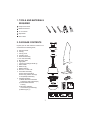
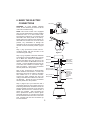
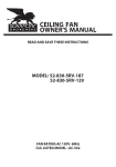
2. PACKAGE CONTENTS
a
Unpack your fan and check the contents. You
should have the following items;
b
a. Hanger bracket
b. Canopy
c. Canopy cover
d. Coupling cover
e. Downrod assembly
f. Fan motor assembly
g. Mounting plate
h. Light plate
i. 75W JD-type halogen bulbs (2)
j. Glass shade
k. Blade set (3)
l. Blade holder(3)
m. Receiver + 6 wire nuts
n. Transmitter assembly
Screws A(2),Screws B(2)
Screws C(2), Plastic anchor(2)
3 volt (#2032) batteries(2)
o. Package hardware
1) Blade attachment hardware:
screws(10),paper washers(10)
2) blade holder hardware:
screw(1)
3) Mounting hardware:
wood screws(2),washers(2)
4) Balancing kit (1)
c
d
k
e
f
l
g
m
h
i
A B
C
j
n
o
1
3. SAFETY RULES
8. Avoid placing objects in the path of the
blades.
1. To reduce the risk of electric shock, insure
electricity has been turned off at the circuit
breaker or fuse box before beginning.
9. To avoid personal injury or damage to the
fan and other items, be cautious when
working around or cleaning the fan.
2. All wiring must be in accordance with the
National Electrical Code and local
electrical codes. Electrical installation
should be performed by a qualified
licensed electrician.
10. Do not use water or detergents when
cleaning the fan or fan blades. A dry dust
cloth or lightly dampened cloth will be
suitable for most cleaning.
3. WARNING: To reduce the risk of shock,
this fan must be installed with an isolating
wall control/switch.
11. After marking electrical connections,
spliced conductors should be turned
upward and pushed carefully up into
outlet box. The wires should be spread
apart with the grounded conductor and
the equipment - grounding conductor on
one side of the outlet box.
4. WARNING: To reduce the risk of personal
injury, use only the two steel screws (and
lock washers) provided with the outlet box
for mounting to the outlet box. Most outlet
boxes commonly used for the support of
lighting fixtures are not acceptable for fan
support and may need to be replaced,
consult a qualified electrician if in doubt.
12. Electrical diagrams are reference only.
Light kit that are not packed with the fan
must be CUL Listed and marked suitable
for use with the model fan you are
installing. Switches must be CUL General
Use Switches. Refer to the Instructions
packaged with the light kits and switches
for proper assembly.
WARNING
TO REDUCE THE RISK OF FIRE,
ELECTRIC SHOCK OR PERSONAL
INJURY, MOUNT FAN TO OUTLET BOX
MARKED "ACCEPTABLE FOR FAN
SUPPORT".
ATTENTION: Canada's Office of Energy
Efficiency requires this fan to be equipped with
a 190 watt limiting device. If lamping exceeds
190 watts, the ceiling fan's light kit will shut off
automatically.
5. The outlet box and support structure must
be securely mounted and capable of
reliably supporting a minimum of 50
pounds. Use only CUL Listed outlet boxes
marked "FOR FAN SUPPORT".
WARNING
6. The fan must be mounted with a minimum
of 7 feet clearance from the trailing edge of
the blades to the floor.
TO REDUCE THE RISK OF PERSONAL
INJURY, DO NOT BEND THE BLADE
BRACKETS (ALSO REFERRED TO AS
FLANGES) DURING ASSEMBLY OR AFTER
INSTALLATION. DO NOT INSERT OBJECTS
IN THE PATH OF THE BLADES.
7. Do not operate reversing switch while fan
blades are in motion. Fan must be turned
off and blades stopped before reversing
blade direction.
2
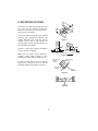
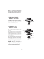
4. MOUNTING OPTIONS
If there isn't an existing CUL listed mounting
box, then read the following instructions.
Disconnect the power by removing fuses or
turning off circuit breakers.
Outlet box
Secure the outlet box directly to the building
structure. Use appropriate fasteners and
building materials. The outlet box and its
support must be able to fully support the
moving weight of the fan (at least 50 lbs). Do
not use plastic outlet boxes.
Figure 1
Figures 1,2 and 3 are examples of different
ways to mount the outlet box.
Outlet box
Note: You may need a longer downrod to
maintain proper blade clearance when
installing on a steep, sloped ceiling. (Fig. 3)
Figure 2
Angled ceiling
maximum
20 angle
To hang your fan where there is an existing
fixture but no ceiling joist, you may need an
installation hanger bar as shown in Figure 4.
Provide strong
support
Recessed
outlet box
Figure 3
Outlet box
Figure 4
3
Ceiling
mounting
plate
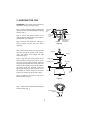
5. HANGING THE FAN
REMEMBER to turn off the power. Follow the
steps below to hang your fan properly:
Step 1. Pass the 120-volt supply wires through
the center hole in the ceiling hanger bracket as
shown in Fig. 5.
CUL Listed
electrial
box
Ceiling
mounting
plate
Step 2. Secure the hanger bracket to the
ceiling outlet box with the screws and washers
provided with your outlet box.
Washers
Hook
120V Wires
Step 3. Remove the hanger pin, locking pin
and set screws from the top of the motor
assembly.
Mounting screws
(supplied with
electrical box)
Figure 5
Step 4. Route wires exiting from the top of the
fan motor through the couping cover, canopy
cover and canopy, then through the ball/
downrod. (Fig. 6)
Downrod
Canopy
Step 5. Align the holes at the bottom of the
downrod with the holes in the collar on top of
the motor housing (Fig.6). Carefully insert the
hanger pin through the holes in the collar and
downrod. Be careful not to jam the pin against
the wiring inside the downrod. Insert the
locking pin through the hole near the end of
the hanger pin until it snaps into its locked
position, as noted in the circle inset of Fig. 6.
Canopy cover
Set screws
Coupling cover
Hanger pin
Step 6. Tighten two set screws on top of the
fan motor firmly. (Fig. 6)
Locking
pin
Figure 6
Step 7. Place the downrod ball into the hanger
bracket socket. (Fig. 7)
Registration slot
Figure 7
4
6. MAKE THE ELECTRIC
CONNECTIONS
Code switch
WARNING: To avoid possible electrical
shock, be sure electricity is turned off at the
main fuse box before wiring.
ON
NOTE: This remote control unit is equipped
with 16 code combinations to prevent possible
interference from or to other remote units.
The frequency switches on your receiver and
transmitter have been preset at the factory.
Please recheck to make sure the switches on
transmitter and receiver are set to the same
position, any combination of settings will
operate the fan as long as the transmitter and
receiver are set to the same position. (Figure
8)
Figure 8
Receiver
Hanger
bracket
Step 1. (Fig. 9) Insert the receiver into the
mounting bracket with the flat side of the
receiver facing the ceiling.
Figure 9
Step 2. (Fig. 10) Motor to Receiver Electrical
Connections: Connect the Black wire from the
fan to Black wire marked "TO MOTOR L".
Connect the White wire from the fan to the
White wire marked "TO MOTOR N" from the
receiver. Connect the Blue wire from the fan
to the Blue wire marked "For bottom Light"
from the receiver. Secure wire connections
with the plastic wire nuts provided.
Outlet box
Green or bare
copper (ground)
Black ("AC IN L")
White ("AC IN N")
Receiver
Black ("to motor L")
Step 3. (Fig. 10) Receiver to House Supply
Wires Electrical Connections: Connect the
black (hot) wire from the ceiling to the black
wire marked "AC in L" from the receiver.
Connect the white (neutral) wire from the
ceiling to the white wire marked "AC in N" from
the Receiver. Secure the wire connections
with the plastic wire nuts provided.
Step 4. (Figure 10) If your outlet box has a
ground wire (green or bare copper) connect it
to the fan ground wires; otherwise connect the
hanging bracket ground wire to the mounting
bracket. Secure the wire connection with a
plastic nut provided. After connecting the
wires, spread them apart so that the green
and white wires are on one side of the outlet
box and black and blue wires are on the other
side. Carefully tuck the wire connections up
into the outlet box.
White (neutral)
Black (hot)
White ("to motor N")
Blue (for bottom light)
Blue ("to motor L")
Black (motor)
Ground (Connect to
(green) ground wire on
hanger bracket
if no house
ground wire
exists.)
White (neutral)
5
Figure 10
Note: Fan must be installed at a maximum
distance of 20 feet from the transmitting unit
for proper signal transmission between the
transmitting unit and the fan's receiving unit.
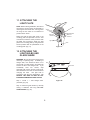
7. INSTALLATION OF
SAFETY SUPPORT
An additional safety support is provided to
prevent the fan from falling. Secure the safety
cable to the ceiling joist with screw and
washer, as illustrated in Figure 11.
Hanger bracket
Safety cable
Figure 11
8. FINISHING THE
INSTALLATION
Step 1. Tuck connections neatly into ceiling
outlet box.
Outlet box
Step 2. Slide the canopy up to hanger bracket
and place the key hole on the canopy over the
screw on the hanger bracket, turn canopy until
it locks in place at the narrow section of the
key holes. (Fig.12)
Hanger
bracket
Screws
Canopy
Step 3. Align the circular hole on canopy with
the remaining hole on the hanger bracket,
secure by tightening the two set screws. Note:
Adjust the canopy screws as necessary until
the canopy and canopy cover are snug.
Canopy cover
Figure 12
WARNING: Make sure tab at bottom of
hanger bracket is properly seated in groove of
hanger ball before attaching canopy to
bracket. Failure to properly seat tab in groove
could cause damage to electrical wiring.
6
9. ATTACHING THE FAN
BLADES
Step 1. Attach the fan blades to the blade holders
by using three screws and paper washers as
shown in Figure 13. Start a screw into the blade
holder, do not tighten. Repeat for the 2 remaining
screws and washers.
Screws
Paper washers
Blade
Step 2. Tighten each screw securely starting with
the center screw. Make sure the blade is straight.
Step3. Remove the screws from the bottom
motor before fasten the blade assemblies to the
bottom motor housing.
Blade holder
Figure 13
Step 4. Tighten the blade assemblies onto
bottom motor by using two screws reviously
removed from the motor.(Figure 14)
CAUTION: Make
tightened securely.
sure
all
screws
Motor
are
Blade assembly
The following procedure should correct most fan
wobble. Check after each step.
Screws
Step 1. Check that all blades and blade holder
screws are secure.
Figure 14
Step 2. Most fan wobble problems are caused
when blade levels are unequal. Check this level
by selecting a point on the ceiling above the tip of
one of the blades. Measure this distance as
shown in Figure 16. Rotate the fan until the next
blade is positioned for measurement. Repeat for
each blade. The distance should be equal within
1/8".
Touching ceiling
Figure 15
10. INSTALLATING THE
MOUNTING PLATE
Step 1. Remove the 1 of 3 screws from the
mounting ring and loosen the other 2 screws.
(Do not remove)
Mounting ring
Step 2. Place the key holes on the mounting
plate over the 2 screws previously loosened
from the mounting ring, turn mounting plate
until it locks in place at the narrow section of
the key holes. Secure by tightening the 2
screws previously loosened and the one
previously removed. (Fig. 16)
Mounting
plate
Screws
Figure 16
7
11. ATTACHING THE
LIGHT PLATE
NOTE: Before starting installation, disconnect
the power by turning off the circuit breaker or
removing the fuse at fuse box. Turning power
off using the fan switch is not sufficient to
prevent electric shock.
Mounting plate
Black wire
connectors
Raise and hold the light plate close to the
mounting plate and proceed to do the wire
connections, follow the same procedure with
the black wire connectors. Attach the light
plate to the mounting plate by using the three
screws provided that are preinstalled on the
mounting plate. (Fig. 17)
White wire
connectors
Light plate
Screw
Figure 17
12. ATTACHING THE
LIGHT BULBS AND
GLASS SHADE
WARNING: Shut off the power supply before
removing or replacing lamp. In handling of
halogen bulb, care should be taken not to
touch it with your bare hands. Oil residue will
shorten the life of the halogen bulb. If you
accidentally come into contact, wipe
thoroughly with a clean, lint-free, cotton cloth.
Allow the bulb to cool off for 10 minutes before
changing the bulb.
Use light bulb in
accordance with the fan's specification. TO
REDUCE THE RISK OF FIRE DO NOT
EXCEED MAXIMUM WATTAGE RATING.
Bulb
Glass shade
Step 1. Install 1 × 75W halogen bulb
(included). (Fig. 18)
Figure 18
Step 2. Install the glass shade by carefully
turning it clockwise until snug. DO NOT
OVERTIGHTEN. (Fig. 18)
8
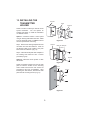
13. INSTALLING THE
TRANSMITTER
HOLDER
Outlet box
Switch
Wall plate
Select a location to install your remote control
system transmitter. You can replace an
existing wall switch or, install the transmitter
on ANY flat surface.
Option 1: Install the remote c ontrol system
using an existing wall switch outlet box. Make
sure the electrical power is TURNED OFF at
the main panel before continuing.
Figure 19
Step 1. Remove the existing wall plate and the
old switch from the wall outlet box. Wire nut
the BLACK leads (hot) together and push
back inside the outlet box. (Fig. 19)
Outlet box
Metal plate Wall plate
Screws A
Step 2. Install the metal plate and wall plate to
the existing wall outlet box with 4 screws
provided. (Fig. 20)
Screws B
Option 2: Install the control system on ANY
flat surface.
Figure 20
Select the desired location and use the wall
plate to mark the location for the mounting
holes. Plastic wall anchors and screws are
provided for this type of installation. After
installing the wall anchors, attached the wall
plate with the mounting screws. (Fig. 21)
Plastic
anchor
Screws C
Holder
Wall
Figure 21
9
14. INSTALLING THE
BATTERY
Remove the back cover on the transmitter and
install both, 3 volt (#2032) batteries that were
included with the remote control. Make sure
the + sign is facing up. (Fig. 22)
15. OPERATING YOUR
TRANSMITTER
Figure 22
Restore power to ceiling fan and test for
proper operation.
A.
,
and
buttons:
These three buttons are used to set the
fan speed as follows:
= low speed
= medium speed
= high speed
B.
button:
This button turns the fan off.
C.
button:
This button controls the light. Press and
release the button to turn the light ON or
OFF. Press and hold the button to set the
desired brightness. The light key has an
auto-resume, it will stay at the same
brightness as the last time it was turned off.
Figure 23
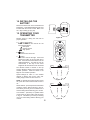
The Reverse switch is located on the top
housing. Slide the switch to the Left for warm
weather operation. Slide the switch to the
Right for cool weather operation.
Speed settings for warm or cool weather
depend on factors such as the room size.
Ceiling height, number of fans and so on.
Figure 24
NOTE: To operate the reverse function on this
fan, press the reverse button while the fan is
off.
Warm weather - (Forward) A downward airflow
creates a cooling effect as shown in Fig. 24.
This allows you to set your air conditioner on a
warmer setting without affecting your comfort.
Cool weather - (Reverse) An upward airflow
moves warm air off the ceiling area as shown
in Fig. 25. This allows you to set your heating
unit on a cooler setting without affecting your
comfort.
Figure 25
10
15. CARE OF YOUR FAN
Here are some suggestions to help you maintain your fan.
1. Because of the fan's natural movement, some connections may become loose. Check the
support connections, brackets, and blade attachments twice a year. Make sure they are
secure. (It is not necessary to remove fan from ceiling.)
2. Clean your fan periodically to help maintain its new appearance over the years. Use only a
soft brush or lint-free cloth to avoid scratching the finish. The plating is sealed with a lacquer
to minimize discoloration or tarnishing. Do not use water when cleaning. This could damage
the motor, or the wood, or possibly cause an electrical shock.
3. You can apply a light coat of furniture polish to the wood blades for additional protection and
enhanced beauty. Cover small scratches with a light application of shoe polish.
4. There is no need to oil your fan. The motor has permanently lubricated sealed ball bearings.
11
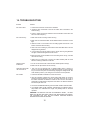
16. TROUBLESHOOTING
Problem
Solution
Fan will not start.
1. Check main and branch circuit fuses or breakers.
2. Check line wire connections to the fan and switch wire connections in the
switch housing.
3. Check to make sure the dip switches from the transmitter and receiver are
set to the same frequency.
Fan sounds noisy.
1. Make sure all motor housing screws are snug.
2. Make sure the screws that attach the fan blade bracket to the motor hub are
tight.
3. Make sure wire nut connections are not rattling against each other or the
interior wall of the switch housing.
4. Allow a 24-hour "breaking-in" period. Most noises associated with a new fan
disappear during this time.
5. If using ceiling fan light kit, make sure the screws securing the glassware
are tight. Check that the light bulb is also secure.
6. Make sure there is a short distance from the ceiling to the canopy. It should
not touch the ceiling.
7. Make sure your ceiling box is secure and rubber isolator pads are used
between mounting bracket and outlet box.
Remote control
malfunction.
1. Do not connect the fan with a wall mounted variable speed control(s).
2. Make sure the dip switches are set correctly.
Lights shut off and will
not come back on.
1. This unit may be equipped with a wattage limiting device. Lamping in
excess of 190 watts will disable your ceiling fan's light kit. To reset your light
kit you must turn the power off and relamp, keeping the wattage under 190
watts. Restore power to your ceiling fan and continue normal operation.
Fan wobble.
1. Check that all blade and blade arm screws are secure.
2. Most fan wobbling problems are caused when blade levels are unequal.
Check this level by selecting a point on the ceiling above the tip of one of
the blades. Measure this distance. Rotate the fan until the next blade is
positioned for measurement. Repeat for each blade. The distance deviation
should be equal within 1/8".
3. Use the enclosed Blade Balancing Kit if the blade wobble is still noticeable.
4. If the blade wobble is still noticeable, interchanging two adjacent (side by
side) blades can redistribute the weight and possibly result in smoother
operation.
WARNING: TO REDUCE THE RISK OF PERSONAL INJURY, DO NOT
BEND THE BLADE ARM WHILE INSTALLING, BALANCING THE BLADES,
OR CLEANING THE FAN. DO NOT INSERT FOREIGN OBJECTS
BETWEEN ROTATING FAN BLADES.
12