Transcript
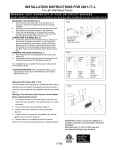
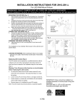
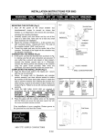
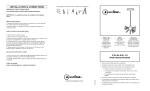
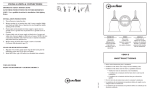
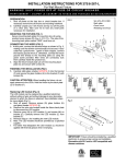
INSTALLATION INSTRUCTIONS FOR 9801-L 9802-L
For Wall Sconce Fixture
READ AND SAVE THESE INSTRUCTIONS
W A R N I N G ! S H U T P O W E R O F F AT F U S E O R C I R C U I T B R E A K E R .
AV E R T I S S E M E N T ! C O U P E R L E C O U R A N T A U N I V E AU D E S F U S I B L E S O U D O D I S J O N C T E U R
ASSEMBLING THE FIXTURE (Fig.1)
1 Shut off power at the fuse box or circuit breaker. If necessary,
2
3
remove the old fixture including the mounting hardware.
Carefully remove the fixture from the carton and check that all
parts are included as show in Figure 1.
Attach circular strap (B) to junction box with two junction box
screws (C)(size:8-32*1/2”L).The “GND” must be face out.
Fig.1
JUNCTION
BOX
Set:
Circular Strap
Mounting Screw(2)
Green Screw
.
CONNECTION THE WIRES (Fig. 2)
4 Connect the electrical wires as shown in Fig.2, making sure that
5
all wire nuts are secured. If your outlet has a ground wire (green
or bare copper), connect the fixture's ground Wire to it.
Otherwise, connect the fixture's ground wire directly to the
circular strap using the green screw provided. Tuck the wire
connections neatly into the junction box.
Align fixture (F) over the mounting screws (E), and secure with
cap nuts (G).
FINISHING THE INSTALLATION (Fig. 1)
6 Carefully slide glass (H) with the marked arrow on the topside,
7
Fig.2
into the fixture and secure with glass support bar (I) and
screws(J).
To prevent moisture from entering the outlet box and causing a
short circuit, use clear caulking (i.e. Indoor/Outdoor silicone
sealant) to outline the outside of fixture back plate where it
meets the wall leaving a space at bottom to allow moisture a
means to escape (Fig.3).
Your installation is now complete. Return power to the junction box
and test the fixture.
CAUTION /ATTENTION: When handling the fixture, do not apply
pressure to the LEDs. Hold the fixture by the base or back plate (F)
only.
Replacing LED module (Fig. 4)
The LED module can be replaced by a qualified electrician without
cutting of wire and without damage to any decorative element to which
the fixture is attached. See installation steps for more details (Fig. 4)
Warning: Turn off power at the circuit breaker before
replacing LED module.
a.
Loosen screw (J) to remove steel bar (I) and glass (H). Loosen
cap nuts (G) remove the wire nuts and remove the fixture.
b.
Loosen screws (L) remove cap (K) and glass plate (P). Loosen
screws (O) and remove LED module (N)L loosen screws (Q) on
LED module and wire fastener (R).
c. Reverse steps a-e for installing the new LED module
d.
e.
Note: The LED module should be provided by a specified supplier.
For better heat dissipation the LED module should be applied
with thermal grease when re-lamping.
IMPORTANT: Fixture should be installed by a qualified
electrician to ensure proper wiring and installation.
Dimmable with C-L (CFL & LED) type and
Incandescent/Halogen type dimmers