1
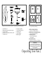
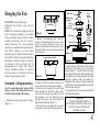
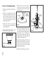
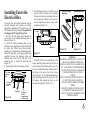
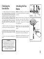
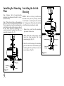
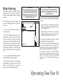
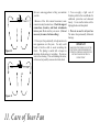
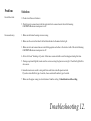
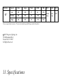
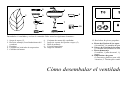
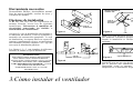
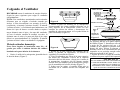
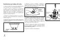
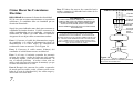
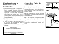
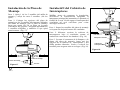
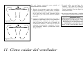
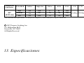
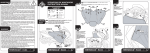
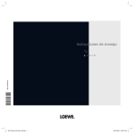
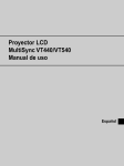
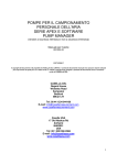
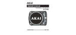
PROGRESS LIGHTING 15-Year Limited Warranty
PROGRESS LIGHTING FAN MOTORS ARE WARRANTED TO THE END USER TO BE
FREE OF ELECTRICAL AND/OR MECHANICAL DEFECTS FOR A PERIOD OF 15
YEARS FROM DATE OF SALE. PULL CHAIN SWITCHES, REVERSE SWITCHES,
CAPACITORS AND METAL FINISHES ARE WARRANTED FOR A PERIOD OF 1 YEAR.
WARPING OF WOODEN OR PLASTIC BLADES IS NOT COVERED BY THIS
WARRANTY.
Date Purchased
Store Purchased
Model No.
THE END USER HAS THE OPTION OF RETURNING THE DEFECTIVE FAN TO THE
PLACE OF PURCHASE DURING THE FIRST 30 DAYS FOR A REPLACEMENT. AFTER
30 DAYS, THE PURCHASER MUST CONTACT PROGRESS LIGHTING FOR REPAIR
OR REPLACEMENT. THE END USER ALSO BEARS THE RESPONSIBILITY FOR ALL
COSTS IN THE REMOVAL, SHIPPING AND REINSTALLATION OF FANS OR PARTS
FOR REPAIR OR REPLACEMENT.
PROGRESS LIGHTING WILL NOT ASSUME LIABILITY OR RESPONSIBILITY FOR
DAMAGES (INCLUDING INCIDENTAL OR CONSEQUENTIAL) CAUSED BY THE
IMPROPER INSTALLATION OR OPERATION OF THE UNIT OR ITS COMPONENT
PARTS, OR BY THE FAILURE OF SUPPORTING HARDWARE NOT SUPPLIED BY
PROGRESS LIGHTING. THIS WARRANTY IS GIVEN IN LIEU OF ALL OTHER
GUARANTEES, WHETHER EXPRESSED OR IMPLIED, AND IS VOIDED IN CASES OF
ABUSE, MISUSE OR IMPROPER HANDLING, NEGLIGENCE, SHIPPING DAMAGE,
UNAUTHORIZED REPAIRS (MADE OR ATTEMPTED) OR UNUSUAL APPLICATION.
Serial No.
Vendor No.
UPC
11221
785247139217
SOME STATES DO NOT ALLOW LIMITATIONS ON HOW LONG AN IMPLIED
WARRANTY LASTS OR THE EXCLUSION OR LIMITATIONS OF INCIDENTAL OR
CONSEQUENTIAL DAMAGES, SO THE ABOVE LIMITATIONS AND EXCLUSIONS
MAY NOT APPLY TO YOU. THIS WARRANTY GIVES YOU SPECIFIC RIGHTS AND
YOU MAY HAVE OTHER RIGHTS WHICH VARY FROM STATE TO STATE.
15-Year Limited Warranty
Safety Rules..................................................................................................................................... 1.
Unpacking Your Fan ........................................................................................................................ 2.
Installing Your Fan ........................................................................................................................... 3.
Operating Your Fan ........................................................................................................................ 10.
Care of Your Fan ............................................................................................................................ 11.
Troubleshooting ............................................................................................................................ 12.
Specifications ............................................................................................................................... 13.
Table of Contents
1. To reduce the risk of electric shock, insure electricity has been turned 9.
off at the circuit breaker or fuse box before beginning.
10.
2. All wiring must be in accordance with the National Electrical Code and
local electrical codes. Electrical installation should be performed by a
qualified licensed electrician.
11.
3. WARNING: To reduce the risk of electrical shock and fire, do not use
this fan with any solid-state fan speed control device.
12.
4. WARNING: To reduce the risk of personal injury, use only the two steel
screws (and lock washers) provided with the outlet box for mounting to
the outlet box. Most outlet boxes commonly used for the support of
lighting fixtures are not acceptable for fan support and may need to be
replaced, consult a qualified electrician if in doubt.
13.
WARNING
TO REDUCE THE RISK OF FIRE, ELECTRIC SHOCK OR PERSONAL
INJURY, MOUNT FAN TO OUTLET BOX MARKED ACCEPTABLE FOR
FAN SUPPORT.
5. The outlet box and support structure must be securely mounted and
capable of reliably supporting a minimum of 50 pounds. Use only UL
Listed outlet boxes marked FOR FAN SUPPORT.
6. The fan must be mounted with a minimum of 7 feet clearance from the
trailing edge of the blades to the floor.
7. WARNING: Use only with light kit marked "Suitable for Use in Damp
Locations" .
8. Do not operate reversing switch while fan blades are in motion. Fan
must be turned off and blades stopped before reversing blade direction.
1. Safety Rules
Avoid placing objects in the path of the blades.
To avoid personal injury or damage to the fan and other items, be
cautious when working around or cleaning the fan.
Do not use water or detergents when cleaning the fan or fan blades. A
dry dust cloth or lightly dampened cloth will be suitable for most
cleaning.
After marking electrical connections, spliced conductors should be
turned upward and pushed carefully up into outlet box. The wires
should be spread apart with the grounded conductor and the
equipment-grounding conductor on one side of the outlet box.
Electrical diagrams are reference only. Light kit that are not packed
with the fan must be UL Listed and marked suitable for use with the
model fan you are installing. Switches must be UL General Use
Switches. Refer to the Instructions packaged with the light kits and
switches for proper assembly.
WARNING
TO REDUCE THE RISK OF PERSONAL INJURY, DO NOT BEND THE
BLADE BRACKETS (ALSO REFERRED TO AS FLANGES) DURING
ASSEMBLY OR AFTER INSTALLATION. DO NOT INSERT OBJECTS IN
THE PATH OF THE BLADES.
WARNING
THIS PRODUCT CONTAINS CHEMICALS KNOWN TO THE STATE OF
CALIFORNIA TO CAUSE CANCER, BIRTH DEFECTS AND /OR OTHER
REPRODUCTIVE HARM. THOROUGHLY WASH HANDS AFTER
INSTALLING, HANDLING, CLEANING, OR OTHERWISE TOUCHING
THIS PRODUCT.
NOTE
READ AND SAVE ALL INSTRUCTIONS!
2
1
6
9
3
a
4
b
7
10
5
8
11
c
d
Unpack your fan and check the contents. You should have the following items:
11. Loose parts bag containing:
1. Set of blades (5)
2. Mounting plate (located inside canopy)
3. Canopy assembly
4. Ball/downrod assembly with safety cable
a. Blade attachment hardware
(16 screws, 16 rubber washers)
b. Blade bracket attachment hardware
(1 screws with lock washers)
c. Mounting hardware
(3 screws, 1 plastic gasket,
1 metal gasket)
d. Electrical hardware
(3 plastic wire connectors, 1 Pull chain)
5. Coupling cover
6. Fan motor assembly
7. Set of blades bracket (5)
8. Mounting plate
9. Switch housing
10. Balancing kit
IMPORTANT
PLEASE REMOVE RUBBER MOTOR
SUPPORT PLATE ON THE BOTTOM OF THE
FAN BEFORE INSTALLING BLADES OR
TESTING MOTOR
Unpacking Your Fan 2.
Tools Required
Figures 1,2 and 3 are examples of different
ways to mount the outlet box.
Phillips screw driver, straight slot screw
driver, adjustable wrench, step ladder, and
wire cutters.
Provide strong
support
Ceiling
Mounting
Plate
Recessed
outlet box
Mounting Options
If there isn't an existing UL listed mounting
box, then read the following instructions.
Disconnect the power by removing fuses or
turning off circuit breakers.
Secure the outlet box directly to the
building structure. Use appropriate
fasteners and building materials. The outlet
box and its support must be able to fully
support the moving weight of the fan (at
least 50 lbs). Do not use plastic outlet
Angled ceiling
maximum
45 angle
Outlet box
Figure 3
Note: You may need a longer downrod to
maintain proper blade clearance when
installing on a steep, sloped ceiling.
Figure 1
WARNING
TO REDUCE THE RISK OF FIRE, ELECTRIC
SHOCK, OR OTHER PERSONAL INJURY,
MOUNT FAN ONLY TO AN OUTLET BOX
MARKED ACCEPTABLE FOR FAN SUPPORT
AND USE THE MOUNTING SCREWS
PROVIDED WITH THE OUTLET BOX. OUTLET
BOXES COMMONLY USED FOR THE SUPPORT
OF LIGHTING FIXTURES MAY NOT BE
ACCEPTABLE FOR FAN SUPPORT AND MAY
NEED TO BE REPLACED. CONSULT A
QUALIFIED ELECTRICIAN IF IN DOUBT.
Figure 4
Outlet box
Figure 2
3. Installing Your Fan
Outlet box
To hang your fan where there is an existing
fixture but no ceiling joist, you may need an
installation hanger bar as shown in Figure 4
(available at your Progress Lighting
Hanging the Fan
REMEMBER to turn off the power.
Follow the steps below to hang your fan
properly.
NOTE: This ceiling fan is supplied with two
types of hanging assemblies; the standard
ceiling installation using the ball/ downrod
assembly mounting, and the "close-toceiling" mounting. The "close-to-ceiling"
mounting is recommended in rooms with less
than 8-foot ceilings or in areas where
additional space is desired from the floor to
the fan blades. When using standard downrod
installation, the distance from the ceiling to
the bottom of the fan blades will be
approximately 14.5 inches. The "close-toceiling" installation reduces the distance
from the ceiling to the bottom of the fan
blades to approximately 9 inches.
Standard ceiling mounting
Note: For mounting angles between 20-45
degrees, remove the canopy bottom cover
installed on the bottom of the canopy.
1. Remove the canopy ring from the canopy.
(Figure 5).
Pin in
locked
position
Motor wires
Ball/downrod
assembly
Canopy ring
Ceiling
canopy
Canopy ring
Figure 5
Collar cover
2. Remove the mounting plate from the
canopy by loosening the four screws on the
top of the canopy. Remove the two nonslotted screws and loosen the slotted screws.
This will enable you to remove the mounting
plate (Figure 6).
Tighten
screws
firmly
Motor collar
Hanger pin
Locking pin
Loosen but do not remove
Figure 7
Remove
Figure 6
3. Remove the bolt, lock pin and loosen set
screws from the top of the motor assembly.
4. Route the wires exiting the top of the fan
motor through the decorative motor collar
cover then the canopy ring. Make sure the
slot openings are on top. Route the wires
through the canopy and then through the
ball/downrod assembly (Figure 7).
5. Loosen, but do not remove, the set screws
on the collar on the top of the motor housing.
6. Align the holes at the bottom of the downrod
with holes in the collar on top of the motor
housing (Figure 7). Carefully insert the hanger
pin through the holes in the collar and downrod.
Be careful not to jam the pin against the wiring
inside the downrod. Insert the locking pin
through the hole near the end of the hanger pin
until it snaps into its locked position as noted in
the circle inset of Figure 7.
7. Re-tighten the set screws on the collar on the
top of the motor housing.
WARNING
FAILURE TO PROPERLY INSTALL
LOCKING PIN AS NOTED IN STEP 6 COULD
RESULT IN FAN LOOSENING AND
POSSIBLY FALLING.
4.
Close-to-Ceiling Mounting
1. Remove the canopy ring from the canopy.
(Figure 5)
2. Remove the mounting plate from the
canopy by loosening the four screws on the
top of the canopy. Remove the two nonslotted screws and loosen the slotted
screws. This will enable you to remove the
mounting plate (Figure 7).
3. Remove the decorative canopy bottom
cover from the canopy by depressing the
three studs (Figure 8).
4. Remove the bolt, lock pin and set screws
from the top of the motor assembly.
Canopy bottom
cover
Figure 8
5. Remove three of six screws and lock
washers (every other one) securing the
motor collar to the top of the fan motor
housing. (Figure 9).
Motor collar
Screw with
lock washer
(3 of 6 places)
Metal
gasket
Ceiling
Canopy
Figure 9
6. Route the wires exiting the top of the fan
motor through the plastic gasket, canopy
ring, canopy and the metal gasket, place the
plastic gasket over the remaining three
screws, place the canopy ring, canopy and
the metal gasket over the motor collar at the
top of the fan motor (Figure 10).
7. Align the three mounting screw holes on the
metal gasket with the holes on the motor
collar at the top of the fan motor and fasten,
using the three screws and lock washers
provided with metal gasket.
8. Tighten the three mounting screws securely.
5.
Screw with
lock washer
Canopy
ring
Plastic
gasket
Figure 10
Installing Fan to the
Electrical Box
The outlet box and support structure must be
securely mounted and capable of reliably
supporting a minimum of 50 pounds. use only
cul listed outlet boxes marked"Acceptable for
Fan Support of 22.7 kgs (50 lbs) or less".
1. Pass the 120-volt supply wires through the
center hole in the ceiling mounting plate as
shown in Figure 11.
2. Install the ceiling mounting plate on the
electrical box by mounting screws provided with
the outlet box. When using close-to-ceiling
mounting, it is important that the mounting plate
be level. If necessary, use leveling washers (not
supplied) between the mounting plate and
electrical box. Note that the flat side of the
mounting plate is toward the electrical box
(Figure 11).
3. Securely tighten the two mounting screws.
CUL Listed
electrical
box
Ceiling
mounting
plate
Washers
120V Wires
Figure 11
Mounting
screws
(supplied with
electrical box)
4. For additional security, install the wood
screws with flat washers (not included)
through outer slots in mounting plate and
into wooden joist. Note: Leave one wood
screw untightened to attach safety cable
from motor (Figure 12).
Ceiling
Close- to-Ceiling
Mounting
Standard Mounting
Wood joist
Outlet box
Figure 13
Figure 13-1
Figure 12
5. Carefully lift the fan assembly up to the
ceiling mounting plate and hang the fan on
the hook under the following two ways: for
Close-to-Ceiling Mounting; utilizing one of
the holes at the outer rim of the ceiling
canopy (Figure 13), for Standard Mounting;
place the looped end of the safety cable out
of hanging ball around the hook on the
ceiling mounting plate. (Figure 13-1)
WARNING
THE HOOK AS SHOWN IN FIG. 13 IS ONLY TO
BALANCE FAN WHILE CONNECTING
WIRING. FAILURE TO HANG AS SHOWN IN
FIG. 13 MAY RESULT IN HOOK BREAKING
CAUSING THE FAN TO FALL. HOOK MUST
PASS FROM INSIDE TO OUTSIDE OF
CANOPY.
THE ILLUSTRATION SHOWN IN FIGURE 13-1
IS ONLY TO PROVIDE A MEANS TO
BALANCE THE FAN WHILE ATTACHING
WIRING.
FAILURE TO COMPLETE INSTALLATION
ACCORDING TO THIS MANUAL WILL
RESULT IN DAMAGE TO PROPERTY AND
PERSONAL INJURY.
6.
Step 1 Connect the fan supply (black) wire and
light supply (blue) wire to the black household
supply wire as shown in Figure 14.
Step 4 After connecting the wires, spread them
apart so that the green and white wires are on one
side of the outlet box and the black wire is on the
other side.
7.
Ground
Conductor
Outlet Box
WARNING
ELECTRICAL DIAGRAMS ARE FOR
REFERENCE ONLY. OPTIONAL USE OF ANY
LIGHT KIT SHALL BE CUL LISTED AND
MARKED SUITABLE FOR USE WITH THIS
FAN.
Step 2. Connect the neutral fan (white) wire to the
white neutral household wire.
Step 3 Connect the two green fan ground wires,
located on the hanging ball and mounting plate, to
the household ground wire. When using Close-toCeiling mounting, there is only one green ground
lead from the ceiling mounting plate since the
ball/downrod assembly is not used.
WHITE
BLACK
WARNING
TO REDUCE THE RISK OF FIRE OR ELECTRIC
SHOCK, DO NOT USE A WALL MOUNTED
SOLID STATE SPEED CONTROL WITH THIS
FAN. IT WILL PERMANENTLY DAMAGE THE
ELECTRONIC CIRCUITRY.
GREEN
Follow the steps below to connect the fan to your
household wiring. Use the wire connecting nuts
supplied with your fan. Secure the connectors with
electrical tape. Make sure there are no loose
strands or connections.
SUPPLY CIRCUIT
WHITE
REMEMBER to disconnect the power. If you feel
that you do not have enough electrical wiring
knowledge or experience, have your fan installed
by a licensed electrician.
Step 5 Turn the connecting nuts upward and
push the wiring into the outlet box.
BLUE
BLACK
Making the Electrical
Connections
BLUE
BLACK
Green
Ground
Lead
Ground to
Downrod
WHITE
WHITE
Figure 14
Diagram indicates optional light kit wiring.
Finishing the
Installation
Attaching the Fan
Blades
1. Carefully unhook the fan from the mounting
plate, for Standard Mounting; you can keep the
cable around the hook and seat the hanger ball
in canopy, make sure the tab in the ring at the
bottom of the canopy is properly seated in the
groove in the hanger ball. Align the locking
slots of the ceiling canopy with the two screws
in the mounting plate. Push up to engage the
slots and turn clockwise to lock in place.
Immediately tighten the two mounting screws
firmly.
NOTE: Your fan blades are reversible. Select
the blade side finish which best accentuates
'
'
your decor.
2. Install the remaining two mounting screws
into the holes in the canopy and tighten firmly.
Step 2 Tighten each screw securely starting
with the center screw. Make sure the blade is
straight.
Rubber
washer
Figure 15
Step 1 Attach the blades to the blade arms
using three screws and rubber washers as
shown in Figure 15. Start a screw into the arm,
do not tighten. Repeat for the 2 remaining
screws and washers.
3. Install the decorative canopy ring by aligning
the ring's slots with the screws in the canopy.
Rotate the ring counter-clockwise to lock in
place.
Step 3 Fasten the blade assembly to the motor
using the motor screws provided. (Figure 16)
4. You may now proceed to attaching the fan
blades.
Step 4 Install an optional light kit if you wish.
Follow the instructions included with the kit.
WARNING
LOCKING SLOTS OF CEILING CANOPY
ARE PROVIDED ONLY AS AN AID TO
MOUNTING. DO NOT LEAVE FAN
ASSEMBLY UNATTENDED UNTIL ALL
FOUR CANOPY SCREWS ARE ENGAGED
AND FIRMLY TIGHTENED.
Screws
Blade
arm
Blade
Motor
Blade arm
Figure 16
8.
Installing the Mounting Installing the Switch
Plate
Housing
Step 1. Remove 1 of the 3 screws from the
mounting ring and loosen the other 2 screws.
(Do not remove)
Step 2. Place the key holes on the mounting
plate over the 2 screws previously loosened
from the mounting ring, turn mounting plate
until it locks in place at the narrow section of
the key holes. Secure by tightening the 2
screws previously loosened and the one
previously removed. (Fig. 17)
NOTE: Before starting installation,
disconnect the power by turning off the
circuit breaker or removing the fuse at fuse
box. Turning power off using the fan switch is
not sufficient to prevent electric shock.
1. Remove the screws from the mounting
plate under the fan motor.
2. While holding the switch housing under
your fan, snap together the wire
connection plug. (Fig. 18)
3. Raise the switch housing to the mounting
plate until the holes in switch housing and
mounting plate line up. Reinsert screws to
secure in place. (Fig. 18)
Connection plug
Switch
housing
Figure 18
Mounting ring
Mounting
plate
Figure 17
9.
Screws
Mounting ring
Screws
Blade blancing
All blades are grouped by weight. Because
natural woods very in density, the fan may
wobble even though the blades are weighed
equally.
WARNING
TO REDUCE THE RISK OF PERSONAL INJURY,
DO NOT BEND THE BLADE HOLDERS
WHILE INSTALLING, BALANCING THE
BLADES, OR CLEANING THE FAN. DO NOT
INSERT FOREIGN OBJECTS BETWEEN
ROTATING FAN BLADES.
The following procedure should correct
most fan wobbling problems. Check after
each step.
Touching
ceiling
1. Check that all blade and blade arm
screws are secure.
2. Most fan wobbling problems are caused
when blade levels are unequal. Check this
level by selecting a point on the ceiling
above the tip of one of the blades. Measure
this distance as shown in Figure 19. Rotate
the fan until the next blade is positioned for
measurement. Repeat for each blade. The
distance deviation should be equal within
1/8".
3. Use the enclosed Blade Balancing Kit if
the blade wobble is still noticeable.
NOTE
WAIT FOR FAN TO STOP BEFORE
CHANGING THE SETTING OF THE
SLIDE SWITCH.
Turn on the power and check the operation of
your fan. There are two pull chains available in
your fan:
1. 3-speed pull chain- it controls the fan speed as
follows: 1 pull- High, 2 pulls- Medium, 3 pullsLow, and 4 pulls- Off.
Speed settings for warm or cool weather
depend on factors such as the room size,
ceiling height, number of fans, and so on.
Figure 19
The slide switch controls directions: forward
(switch left) or reverse (switch right).
Warm weather - (Forward) A downward air flow
creates a cooling effect as shown in Figure 20.
This allows you to set your air conditioner on a
higher setting without affecting your comfort.
Cool weather - (Reverse) An upward airflow
moves warm air off the ceiling area as shown in
Figure 21. This allows you to set your heating
unit on a lower setting without affecting your
comfort.
4. If the blade wobble is still noticeable,
interchanging two adjacent (side by side)
blades can redistribute the weight and
possibly result in smoother operation.
Operating Your Fan 10.
Here are some suggestions to help you maintain
your fan
1.Because of the fan's natural movement, some
connections may become loose. Check the support
connections, brackets, and blade attachments
twice a year. Make sure they are secure. (It is not
necessary to remove fan from ceiling.)
Figure 20
2. Clean your fan periodically to help maintain its
new appearance over the years. Use only a soft
brush or lint-free cloth to avoid scratching the
finish. The plating is sealed with a lacquer to
minimize discoloration or tarnishing. Do not use
water when cleaning. This could damage the motor,
or the wood, or possibly cause an electrical shock.
Figure 21
11. Care of Your Fan
3. You can apply a light coat of
furniture polish to the wood blades for
additional protection and enhanced
beauty. Cover small scratches with a
light application of shoe polish.
4. There is no need to oil your fan.
The motor has permanently lubricated
bearings.
IMPORTANT
MAKE SURE THE POWER IS OFF AT THE
ELECTRICAL PANEL BOX BEFORE YOU
ATTEMPT ANY REPAIRS. REFER TO THE
SECTION "MAKING ELECTRICAL
CONNECTIONS"
Problem
Solution
Fan will not start.
1.Check circuit fuses or breakers.
2. Check line wire connections to the fan and switch wire connections in the switch housing.
CAUTION: Make sure main power is off.
Fan sounds noisy.
1. Make sure all motor housing screws are snug.
2. Make sure the screws that attach the fan blade bracket to the motor hub is tight.
3. Make sure wire nut connections are not rubbing against each other or the interior wall of the switch housing.
CAUTION: Make sure main power is off.
4. Allow a 24-hour "breaking-in" period. Most noise associated with a new fan disappear during this time.
5. If using an optional light kit, make sure the screws securing the glassware are tight. Check that light bulb is
also secure.
6.Some fan motors are sensitive to signals from solid-state variable speed controls.
If you have installed this type of control, choose and install another type of control.
7. Make sure the upper canopy is a short distance from the ceiling. It should not touch the ceiling.
Troubleshooting 12.
Fan Size
52"
Speed
Volts
Amps
Watts
RPM
CFM
Low
120
0.28
17
64
1510
Medium
120
0.43
38
118
2766
High
120
0.59
70
170
4150
These are approximate measures. They do not include Amps and Wattage used by the light kit.
C 2007 Progress Lighting, Inc.
701 Millennium Blvd
Greenville, SC 29607
All Rights Reserved
13. Specifications
N.W.
G.W.
C.F.
11.64
kgs
13.2
kgs
2.37'
Garantía Limitada de 15 Años
LOS VENTILADORES PROGRESS LIGHTING GARANTIZAN AL CONSUMIDOR ESTAR
LIBRES DE DEFECTOS ELÉCTRICOS Y/O MECÁNICOS PRO UN PERÍODO DE 15 AÑOS A
PARTIR DE LA FECHA DE VENTA. LOS INTERRUPTORES CON CADENA, LOS
INTERRUPTORES DE INVERSIÓN. LOS CONDENSADORES Y LAS TERMINACIONES
METÁLICAS ESTÁN GARANTIZADAS POR UN PERÍODO DE 1 AÑO. LAS PALETAS
PANDEADAS DE MADERA O PLÁSTICO NO ESTÁN CUBIERTAS POR ESTA GARANTÍA.
EL CONSUMIDOR TIENE LA OPCIÓN DE DEVOLVER EL VENTILADOR DEFECTUOSO
PARA SU CAMBIO AL NEGOCIO DE ADQUISICIÓN DURANTE LOS 30 DÍAS
SIGUIENTES. DESPUÉS DE 30 DÍAS, EL COMPRADOR DEBE CONTACTAR PROGRESS
LIGHTING PARA LA REPARACIÓN O REEMPLAZO. EL CONSUMIDOR SE HARÁ CARGO
DE TODOS LOS COSTOS DE TRANSPORTE, EXPEDICIÓN Y REINSTALACIÓN DE LOS
VENTILADORES O DE LAS PARTES PARA REPARAR O REEEMPLAZAR.
PROGRESS LIGHTING NO ASUMIRÁ OBLIGACIONES O RESPONSABILIDAD POR
DAÑOS (INCLUYENDO INCIDENTALES O CONSIGUIENTES) CAUSADOS POR EL USO O
LA INSTALACIÓN IMPROPIA DE LA UNIDAD O DE SUS PARTES COMPONENTES, O POR
LA FALLA DEL EQUIPO DE SOPORTE NO SUMINISTARADO POR PROGRESS LIGHTING
ESTA GARANTÍA ESTÁ DADA EN LUGAR DE TODAS LAS OTRAS GARANTÍAS, SEAN
ÉSTAS EXPRESAS O IMPLÍCITAS, Y ES INVÍCIDA EN CASOS DE ABUSO, USO O
MANEJO INCORRECTOS, TRATAMIENTO NEGLIGENTE, DAÑOS OCASIONADOS POR
EL TRANSPORTE, REPARACIONES NO AUTORIZADAS (REALIZADAS O TENTATIVAS) O
APLICACIÓN INUSUAL.
Fecha de compra
Lugar de compra
N de modelo.
N de serie
Numero de vendedor
UPC
11221
785247139217
ALGUNOS ESTADOS NO RECONOCEN LIMITACIONES EN EL TÉRMINO DE LA
GARANTÍA IMPLICADA O LA EXCLUSIÓN O LIMITACIÓN DE LOS DAÑOS
INCIDENTALES O CONSIGUIENTES, ENTONCES LAS LIMITACIONES Y EXCLUSIONES
PRECEDENTES PUEDEN NO SER APLICABLES A UD. ESTA GARANTÍA LE OTORGA
DERECHOS ESPECÍFICOS Y UD. PUEDE TENER OTROS DERECHOS QUE VARÍEN DE
ESTADO EN ESTADO.
Garantía Limitada de 15 Años
Normas de seguridad ...................................................................................................................................................................... 1.
Cómo desembalar el ventilador ...................................................................................................................................................... 2.
Cómo instalar el ventilador ............................................................................................................................................................ 3.
Operando su transmisor ..............................................................................................................................................................10.
Cómo cuidar del ventilador .......................................................................................................................................................... 11.
Resolución de problemas ............................................................................................................................................................. 12.
Especificaciones ........................................................................................................................................................................... 13.
Tabla de Contenido
1. Para reducir el riesgo de eléctrocución, asegurarse de que la eléctricidad se
ha desactivado en el cortacircuitos o caja de fusibles antes de comenzar.
2. Todo cableado debe relizarse conforme al Código Electrico Nacional y los
códigos electricos locales. La instalación eléctrica debe ser relazada por un
eléctricista registrado calificado.
3. ADVERTENCIA: Para reducir el riesgo de una electrocuion e incendio, no
usar este ventilador con ningun dispositivo de esto s lido para control de la
velocidad del ventilador.
4. ADVERTENCIA: Para reducir el riesgo de daños personales, utilice sólo
los dos tornillos de acero (y arandelas de bloqueo) suministrados en la caja
del enchufe para el montaje en ésta. La mayoría de cajas de enchufes usadas
comúnmente para instalaciones de luz no sirven para soportar un ventilador y
puede que necesite cambiarlas; si tiene dudas, consulte con un electricista
cualificado.
ADVERTENCIA
PARA REDUCIR EL RIESGO DE INCENDIO ELECTROCUCIÓN O
LESIONES PERSONALES. MONTAR EL VENTILADOR EN UNA CAJA DE
DISTRIBUCIÓN MARCADA CÓMO ACEPTABLE PARA SOPORTE DE
VENTILADORES.
5. La caja de distribución y la estructura de soporte deben estar montados de
manera segura y deben ser capaces de soportar, de manera confiable,
unminimo de 35 libras (15.9 kilogramos). Usar solamente cajas de
distribución listadas por U.L. marcadas "PARA SOPORTEDE
VENTILADORES".
6. EL ventilador debe estar montado con un m nimo de 7 pies (213cm) de
espacio libre desde el borde posterior de las aspas hasta el piso.
7. ADVERTENCIA: Utilice solamente con "conveniente marcada kit ligero
para el uso en localizaciones húmedas".
8. No operar el conmutador inversor mientras las aspas del ventilador están
en movimiento. EI ventilador debe estar desacivado y las aspas estáticas
antes de invertir la dirección de la aspas.
1. Normas de seguridad
9. Evitar colocar objetos qen interfiera el giro de las aspas.
10. Para evitar lesiones personales o da os al ventilador y otros articulos, tener
cuidado al trabajar cerca del ventilador o al limpiarlo.
11. No usar agua o detergentes al limpiar el ventilador o las aspas del ventilador.
Para la mayoria de los propsitos de limpieza, un paño seco o ligeramente
humedecido será apropiado.
12. Despues de realizar las conexiones eléctricas, los conductores empalmados
se deben voltear hacia arriba y se deben empujar con cuidado hacia dentro
de la caja de distribución. Los cables deben estar separados, con el
conductor a tierra y el conductor a tierra del equipo en un lado de la caja de
distribución.
13. Los diagramas eléctricos son para referencia únicamente. Los juegos de
iluminación que no estén embalados con el ventilador deben estar Listados
por U.L. y marcados como apropiados para ser usados con el modelo de
ventilador que se está instalando. Los interruptores deberán ser
Interruptores para uso general U.L. Réfierase a las instrucciónes embaladas
con los juegos de iluminación e interruptores para obtener información
sobre el montaje adecuado.
ADVERTENCIA
ESTE PRODUCTO CONTIENE SUBSTANCIAS QUÍMICAS QUE SEGÚN EL
ESTADO DE CALIFORNIA CAUSA CÁNCER, DEFECTOS DE NACIMIENTO Y
(O) DAÑO AL SISTEMA REPRODUCTOR. LAVARSE BIEN LAS MANOS
DESPUÉS DE INSTALAR, MANIPULAR, LIMPIAR O TOCAR DE MANERA
ALGUNA ESTE PRODUCTO.
ADVERTENCIA
PARA REDUCIR EL RIESGO DE LESIONES PERSONALES, NO DOBLAR LOS
SOPORTES DE LAS ASPAS (TAMBIEN LLAMADOS"REBORDES" DURANTE
EL MONTAJE O DESPUES DE LA INSTALACIÓN NO INSERTAR OBJETOS EN
LA TRAYECTORIA DE LAS ASPAS.
NOTA
!LEER Y GUARDAR TODAS LAS INSTRUCCIONES!
2
1
6
9
3
a
b
7
4
10
8
5
11
c
d
Desembalar el ventilador y revisar el contenido. Debe tener los siguientes elementos:
1. Juego de aspas (5)
2. Placa de montaje (Localizada dentro del
escudete)
3. Escudete
4. Conjunto de bola/tubo de suspension
5. Cubridor del motor
6.
7.
8.
9.
10.
Conjunto de motor del ventilador.
Juego de soporte de fijación a aspas (5)
Plato de montaje
Caja del interruptor
Juego de balanceo
12. Dos bolsas de piezas pequeñas:
a. Piezas de fijacion de las aspas
(16 tornillos, 16 arandelas de goma )
b. Piezas de fijación de los soporte de pala
(11 tornillos con arandelas de cierre)
c. Piezas demontaje
(3 tornillos, 1 junta de metal, 1 junta de
goma)
d. Empacadura de goma
(3 conectores plasticos para cables)
electricos, 2 Tirador para ventilador)
Cómo desembalar el ventilador 2.
Herramienta necesarias
Angulo máximo en
el techo: 45°
Destornillador Phillips, destornillador normal,
llave de tuercas ajustable, escalera de tijera, y
cortadoras de alambre.
Opciones de instalación
Soportede
Montajeen el
Techo
Caja de
Distribución
Recedida
Si no hay una caja con UL registración de
montaje existente, sirvase leer las siguientes
instrucciones. Desconectar el suministro de
electricidad removiendo los fusibles o
desactivando los cortacircuitos.
Asegurar la caja de distribución directamente a
la estructura del edificio. Usar los sujetadores y
meteriales de construcción apropiados. La caja
de distribución y su soporte deben ser capaces de
soportar completamente el peso en movimiento
del ventilador (al menos 50 libras o 22.7 kgs.)No
usar cajas de distribución plásticas.
Proveer Soporte Fuerte
Caja de
Distribución
Figura 3
Figura 1
Nota: Ud. Puede necesitar una barra de extension
para mantener la distancia apropiada de las aspas
cuando la instalación se efectúe en un techo
inclinado.
Las figuras 1,2 y 3 son ejemplos de diferentes
maneras de montar la caja de distribución.
ADVERTENCIA
PARA REDUCIR EL RIESGO DE INCENDIO,
ELECTROCUCIÓN O DAÑO PERSONAL,
INSTALAR EL VENTILADOR A UNA CAJA DE
DISTRIBUCION MARCADA "ACEPTADA
PARA SOPORTAR VENTILADOR" Y USAR
LOS TORNILLOS DE MONTAJE
SUMINISTRADOS CON LA CAJA DE
DISTRIBUCION
Caja de
Distribución
Figura 2
3.Cómo instalar el ventilador
Figura 4
Caja de distribución
Para colgar su ventilador donde ya existe una
instalación pero no una viga de techo, es possible
que se necesite una instalación de barra de
suspención como se muestra la Figura 4
(disponible en su distribuidor Progress Lighting).
Colgando el Ventilador
RECORDAR cortar el suministro de energía eléctricia.
Seguir los pasos siguientes para colgar su ventilador
apropiadamente.
NOTA: Este ventiladores suministrado con dos métodos
diferentes para ser colgado; el método estandar que
incluye el tubo descendiente con montaje de bola y
receptáculo y el montaje "próximo al techo". El método
"próximo al techo", se recomienda para habitaciones con
menos de 8 pies de altura o en areas donde se requiera
mayor distancia entre el piso y las aspas del ventilador.
Al usar el método estandar de montaje con tubo, la
distáncia entre el techo y la parte más baja de las aspas
deberá ser aproximadamente 14.5 pulgadas. El método
"próximo al techo" reduce esta distancia a 9 pulgadas.
Cables del motor
Anillo decorativo
Conjunto de
bola/tubo de
suspensión
Escudete
para el techo
Anillo
decorativo
Chaveta en
la posición
asegurada
Figura 5
Cubridor del motor
2. Retire la placa de montaje de la marquesina
desenroscando los cuatro tornillos ubicados en la
parte superior de la marquesina. Retire los dos
tornillos de cabeza sin ranura y desenrosque los
tornillos de cabeza con ranura. Asi se podrá retirar la
placa de montaje (Figura 6).
Soltar pero NO remover
Collain del motor
Pasador de
suspensión
Apretar los
tornillors
confimeza
Chavetar de
seguridad
Figura 7
6. Alinee los agujeros de la parte inferior del tubo con
los agujeros del aro en la parte superior de la cubierta
del motor (Figura 7). Introduzca con cuidado el pasador
Metodo estándar demontaje
a través de los agujeros del aro y del tubo. Tenga
cuidado de no empujar el pasador contra los alambres
Nota: Para ángulos de instalación entre 20 y 45
Figura 6
dentro del tubo. Inserte la chaveta en los agujeros
grados, por retire el cubierta inferior del escudete
ubicados cerca de la extremidad del pasador hasta que
instalada en la parte inferior de la abertura.
3. Retirar de la parte superior del conjunto del de enganche en su posición cerrada como se nota en la
motor, el pasador de suspensión, la chaveta de insercion redonda de la Figura 7.
7. Apriete de nuevo el juego de tornillos que esta sobre
1. Retire el anillo de la márquesina girandolo hacia seguridad y los tornillos de fijación.
4. Pase los alambres que salen de la parte superior el collar en la parte superior del caparazón del motor.
la derecha hasta. (Figura 5)
del motor del ventilador a través de la cubierta
ADVERTENCIA
decorativa del aro del motor y luego por el anillo de
la marquesina. Asegúrese que las ranuras queden EL NO APPRETAR ADECUADAMENTE LA TUERCA
COMO SE MUESTRA EN EL PASO Y NO APRETAR
encima. Pase los alambres por la marquesina y luego
ADECUADAMENTE LOS TORNILLOS COMO SE
por el ensamblaje de la bola/ del tubo (Figura 7).
MUESTRA EN EL PASO 6, PUEDE RESULTAR EN
5. Soltar pero no quitar, el tornillo fijado que se
QUE EL VENTILATOR SE SUELTE Y CAIGA.
encuentra en el collarin encima del conjunto del
motor.
Remover
4.
Instalacion próxima al techo
5. Remover 3 de los 6 tornillos y arandelas de
seguridad (dejando uno por medio) asegurando el
collarín del motor localizado en la parte superior
1. Retire el anillo de la marquesina girándolo hacia
de la cubierta del motor (Figura 9).
la derecha hasta que se desenganche (Figura 5).
2. Retire la placa de montaje de la marquesina
desenroscando los cuatro tornillos ubicados en la
parte superior de la marquesina. Retire los dos
tornillos de cabeza sin ranura y desenrosque los
tornillos de cabeza con ranura. Asi se podrá retirar
la placa de montaje (Figura 6).
Collarin
Tornillos y
arandela de
seguridad
(3 de 6 lugares)
Tornillos y
arandela de
seguridad
Empacadura
de metal
Escudeta
para el
techo
Figura 9
3. Remover la cubierta decorativa en la parte de
abajo del escudete presianando los 3 botones de la
6. Coloque el sello plastico sobre los 3 tornillos
cubierta (Figura 8).
restantes, acomode los cables existentes en la parte
4. Retirar de la parte superior del conjunto del de motor, superior del motor del ventilador pasandolos a
el pasador de suspensión, la chaveta de seguridad y los traves del escudete. Luego coloque el anillo del
escudete y el escudete de techo sobre el collar en la
tornillos de fijación.
parte superior del motor (Figura 10).
7. Alinee los agujeros de montaje con los agujeros
de la parte superior del motor y ajuestelos usando
los tres tornillos y arandelas suministrados con el
sello metalico (Figura 10).
Cubierta del
escudete
Figura 8
5.
8. Apretar los tornillos adecuadamente.
Anillo
decorativo
Empacadura
de goma
Figura 10
4. Para mayor seguridad, instale dos tornillos de
madera con las arandelas planas (no
proporcionadas) a través de las ranuras externas
en la placa de montaje y en la vigueta de madera.
La caja de distribucion y el soporte de la Nota: Deje un tornillo de madera aflojado para
estructura debe estar seguramente montado y ser
capas de confiablemente soportar el minimo de fijar el cable de seguridad del motor. (Figura 12)
22.7kgs (50lbs) o menos.
Instalacion del Ventilador a la
Caja Electrica
1. Introduzca los cables de suministro de 120 voltios
en el agujero céntrico de la placa de montaje ubicada
en el cieloraso como se muestra en la Figura 11.
2. Instale la placa de montaje sobre la caja de
conexiones usando los tornillos provistos con la caja
de conexiones. Fíjese que el lado plano de la placa de
montaje quede junta a la caja de conexiones (Figura
11). Cuando instale el ventilador próximo al techo es
importante que el soporte de montaje rápido este
nivelado. De ser necesario use arandelas de nivel (no
incluidas) entre el soporte de montaje y la caja de
electricidad. El lado plano del soporte de montaje
rápido deberá estar hacia la caja de electricidad
(Figura 11).
3. Ajuste de manera segura los dos tornillos de
montaje.
Caja de
Distribución
aprobada
por CUL
Arandelas
Montaje
Montaje Próximo
al Techo
Montaje Estandar
Vigueta de
madera
Caja de distribucion
Figura 12
5. Levante el montaje del ventilador con cuidado
hacia la placa de montaje en el techo y cuelgue el
ventilador en el gancho de estos dos modos: para
el montaje cerca del techo; utilice uno de los
agujeros en el anillo exterior de la tapa del techo
(Figura 13); para el montaje estándar, coloque el
extremo con lazo del cable de seguridad fuera de
la bola de suspensión alrededor del gancho en la
placa de montaje en el techo. (Figura 13-1)
Figura 13
Figura 13-1
WARNING
EL GANCHO QUE APARECE EN LA FIG.13 SÓLO ES
PARA EQUILIBRAR EL VENTILADOR DURANTE
LA CONEXIÓN DE LOS CABLES. SI NO SE CUELGA
COMO EN LA FIG. 13 PUEDE PROVOCAR LA
ROTURA DEL GANCHO Y EL VENTILADOR
PODRÍA CAERSE. EL GANCHO DEBE PASAR DEL
INTERIOR AL EXTERIOR DE LA CARCASA.
LA ILUSTRACIÓN DE LA FIGURA 13-1 SIRVE SÓLO
COMO MEDIO PARÍA EQUILIBRAR EL
VENTILADOR DURANTE LA CONEXIÓN DE LOS
CABLES.
SI NO COMPLETA LA INSTALACIÓN SIGUIENDO
ESTE MANUAL PODRA PROVOCAR DAÑOS A LA
PROPIEDAD Y DAÑOS PERSONALES.
Placa de
montaje de
techo
Cables de 120V
Figura 11
Tornillos de
montaje
(suplidos en la
caja eléctrica)
6.
Paso. 1 Conectar el cable de alimentacion (negro)
de ventilador y el cable de alimentacion (azul) de
alimentacion l al cable negro de alimentacion
residencial cómo se muestra en la Figura 14.
ADVERTENCIA
LOS DIAGRAMAS ELÉCTRICOS SON PARA
REFERENCIA ÚNICAMENTE. LOS JUEGOS DE
ILUMINACIÓN QUE NO ESTÉN EMBALADOS CON
EL VENTILADOR DEBEN ESTAR LISTADOS POR
CUL Y MARCADOS COMO APROPIADOS PARA
SER USADOS CON EL MODELO DE VENTILADOR
QUE SE ESTÁ INSTALANDO.
Paso. 2 Conectar el cable neutro (blanco) del
ventilador al cable blanco neutro residencial.
Paso 3 Al usar el método estandar de montaje
existen dos cables verdes de bola uno del soporte
de montaje rápido y otro del tubo descendente. Si
usa el método próximo al techo existe solo un
cable verde de tierra del soporte de montaje ya que
el tubo descendente no se usa.
Paso 4 Después de conectar los cables. separarlos
de modo que los cables verde y blanco estén en un
lado de la caja de distribución y los cables negro y
azul estén en el otro lado.
7.
BLANCO
NEGRO
ADVERTENCIA
PARA REDUCIR EL RIESGO DE FUEGO O
CORTO CIRCUITO NO SE RECOMIENDA EL
USO DE CONTROL DE VELOCIDAD PARA
ESTE VENTILADOR, ESTO CAUSARIA
DAÑO PERMANTENTE EN LOS CIRCUITOS
ELECTRICOS.
Conductor
a tierra
VERDE
Seguir los pasos indicados mas abajo para conectar su
ventilador al circuito electrico. Usar los conectores de
cables suministrados con su ventilador. Asegurar los
sconectores de cables con cinta adhesive electrica.
Asegurese de no dejar cables o conexiones sueltas.
CIRCUITO DE A LIMENTACIÓN
BLANCO
RECORDAR desconectar la fuenta de electricidad.
Si Ud. cree que no tiene conocimientos ni experiencia
suficientes, su ventilador debe ser instalado por un
electricista licenciado..
Paso 5 Voltear las tuercas de conexión hacia
arriba y empujar el cableado hacia detro de la
caja de distribución.
AZUL
NEGRO
Cómo Hacer las Conexiones
Electrias
Caja de
distribución
Hilo de tierra
verde
Conexión a
tierra para la
barra
descendente
AZUL
BLANCO
NEGRO
BLANCO
Figura 14
El diagrama indica el cableado para el juego
opcional de iluminación.
Finalizacion de la
Instalación del
Ventilador
1. Desenganche con cuidado el ventilador de la
placa de montaje, para el montaje estándar;
puede mantener el cable alrededor del gancho y
encajar la bola de suspensión en la carcasa,
compruebe que la pestaña del anillo en la parte
inferior de la carcasa quede correctamente
ajustada a la ranura de la bola de suspensión.
Alinee las ranuras de cierre de la carcasa del
techo con los dos tornillos de la placa de
montaje. Empuje hacia arriba para ajustar las
ranuras y gire en sentido horario para
bloquearlo. Apriete inmediatamente los dos
tornillos de montaje.
Juntar Las Palas del
Ventilador
Paso 1: Se pegan las palas a los soportes usando
los tornillos y las arandelas de goma provistos
como indicado en Fig 15. Inserta un tornillo en el
soporte sin apretarlo. Repite el paso por los otros 2
tornillos y arandelas.
Tornillos
Arandelas
de goma
Soporte de pala
15
Paso 2: Apreta todos los tornillos fimemente
empezando con el tornillo cortador. Asgúrate de
que la pala esté recta.
2. Instale los dos tornillos de montaje restantes en
los agujeros de la carcasa y apriete con firmeza.
Paso 3 Alinie los agujeros de la abrazadera con los
del motor y asegurela con los tornillos suministrados.
Apriete bien los tornillos. (Figura 16).
3. Instale el anillo de la carcasa decorativa
alineando las ranuras del anillo con los tornillos
de la carcasa. Gire el contador del anillo en
sentido horario para bloquearlo.
Paso 4: Se agrega un juego de luz opcional si lo
desea. Observe las instrucciones incluidas con el
juego.
Pala
Motor
Soporte de pala
4. Ahora puede continuar montando las palas del
ventilador.
Figura 16
ADVERTENCIA
LAS RANURAS DE SEGURIDAD DEL
ESCUDETE SON SUMINISTRADAS
SOLAMENTE COMO A YUDA EN EL MONTAJE.
NO DEJAR EL VENTILADOR DESATENDIDO
HASTA QUE LOS CUATRO TORNILLOS DE LA
CUPULA ESTEN COLOCADOS Y APRETADOS
FIRMEMENTE.
8.
Instalación de la Placa de
Montaje
InstalacióN del Cubierta de
Interruptores
Paso 1. Quite 1 de los 3 tornillos del anillo de NOTA: Antes de comenzar la instalación,
montaje y afloje los otros 2 tornillos. (No los desconecte la alimentación apagando el
quite)
interruptor principal del automático o quitando el
Paso 2. Coloque los agujeros del plato de fusible de su caja. Si sólo apaga el interruptor del
montaje en los 2 tornillos previamente aflojados ventilador no será suficiente para evitar
del anillo de montaje, gire el plato de montaje descargas eléctricas.
hasta que quede fijo en su lugar en la parte
estrecha de los agujeros. Asegúrela apretando los Paso 1. Saque los tornillos del placa de montaje
2 tornillos aflojados y también el que quitó en la parte de abajo del motor del ventilador.
anteriormente. (Fig. 17)
Paso 2. Mientras sostiene la cubierta de
interruptores bajo el ventilador, monte el
enchufe de conexión de los alambres. (Fig. 18)
Clavijas de conexión
Paso 3. Levante el estructura de la lámpara, a la
altura del placa de montaje, hasta que los
agujeros de la cubierta de interruptores y del
anillo queden alineados. Vuelva a colocar los
tornillos para asegurar todo en su lugar. (Fig. 18)
Cubierta de
interruptores
Figura 18
Anillo de montaje
Placa de montaje
Figura 17
9.
Tornillos
Placa de
montaje
Tornillos
Todas las aspas están agrupadas por peso.
Debido a que la desidad de las maderas naturales
varía, el ventilador podría oscilar aún cuando el
peso de las aspas esté equilibrado.
El siguiente proceimiento deberia mayor parte
de la oscilación del ventilador. corregir la
Verificar después de cada paso.
ADVERTENCIA
PARA REDUIR RIESGO DE LESIONES
PERSONALES. NO DOBLAR LOS SUJET
ADORES DE ASPAS MIENTRAS SE REALIZA
LA INSTALACIÓN. EL BALANCEO DE LAS
ASPAS O SU LIMPIEZA. NO INSERTAR
OBJETOS EXTRANOS ENTRE LAS ASPAS DEL
VENTILADOR EN ROTACIÓN
1. Verificar que todos los tornillos de aspas y de
soportes de aspas estén seguros.
2. La mayoría de los problemas de oscilación se
originan cuando los niveles de las aspas son
desiguales. Revisar esté nivel por medio de
seleccionar un punto del techo por encima de
la punta de una de las aspas. Medir esta
distancia como se muestra en la Figura 19.
Rotar el ventilador hasta que la siguiente aspa
esté ubicada para medición. procedimiento
para cada aspa. Las medi repetir el das hacer
fucional deben mantenerse dentro de 1/8
pulgadas (3mm). el ventilador durante 10
minutos.
3. Usar el juego de balanceo de aspas incluido si
aún se puede notar la oscilación.
4. Si la oscilación de las aspas todavía se puede
notar, el intercambio de dos aspas adyacentes
(lado a lado) puede redistribuir el peso y es
posible que resulte en un funcionamiento más
uniforme.
En contacto
con el techo
NOTA
ESPERE A QUE EL VENTILADOR PARE
ANTES DE CAMBIAR LA POSICIÓN
DEL INTERRUPTOR DESLIZANTE.
Conecte la alimentación y compruebe el
funcionamiento del ventilador. Hay 2 cordones en
el ventilador:
1. Cordán para 3 velocidades- controla la
velocidad del ventilador como sigue: 1 tir nAlta, 2 tirones- Media, 3 tirones- Baja y 4
tirones- Apagado.
La configuración de la velocidad para
temperatura fría o templada depende de
factores como el tama o de la habitación,
altura del techo, número de ventiladores, etc.
Figura 19
El interruptor deslizante controla las direcciones:
adelante (interruptor abajo) o atrós (interruptor
arriba).
Temperatura templada - (Adelante) el flujo del
aire hacia abajo crea un efecto enfriador como se
muestra en la figura 20. Esto le permite colocar su
aire acondicionado en un lugar más alto sin que
afecte a su confort.
Temperatura fría - (Reversa) el flujo del aire hacia
arriba quita el aire caliente del techo como aparece
en la figura 21. Esto le permite colocar el radiador
en un lugar más bajo sin que afecte a su confort.
Cómo cuidar del ventilador 10.
He aqui algunas sugerencias para ayudarle el
mantenimiento del ventilodor.
1. Debido al movimiento natural del ventilador,
algunas conexiones se podrian aflojar. Examinar
las conexiones del soporte, soportes, y accessorios
de las aspas dos veces al año. Asgurarse de que
estén seguros. (No es necesario retirar el venitlador
del techo).
Figura 20
2. Limpiar el ventilador periódicamente para ayudar a
mantener su apariencia de nuevo con el transcurso
del tiempo. Usar solamente un cepillo suave o
paño sin hilas para evitar rayar el acadado. El
recubrimiento metálico se sella con una laca para
minimizar la decoloración o manchado. No usar
agua al limpiarlo. madera, o posiblemente causar
choque eléctrico.
Figura 21
11. Cómo cuidar del ventilador
3. Se puede aplicar una capa ligera de pulidor para
muebles a las aspas de madera para brindar
protección adicional y realzar su belleza. Cubrir los
rayones pequeños con una ligera aplicación de
betún para calzado.
4. No hay necesidad de aceitar el ventilador. El motor
tiene cojinetes permanentemente lubricados.
ADVERTENCIA
ASEGURARSE DE QUE LA ELECTRICIDAD
ESTÉ DESACTIVADA EN EL TABLERO DE
DISTRIBUCIÓN ELÉCTRICA ANTES DE
INTENTAR CUALQUIER REPARACIÓN
REFERIRSE A LA SECCIÓ "CÓMO
EFECTUAR CONEXIONES ELÉCTRICAS"
Problema
Solución
El ventilador no
arranca.
1. Revisar los fusibles o interruptores de circuitos.
2. Verificar las conexiones de cables de linea al ventilador y conexiones de cable del interruptor
PRECAUCIÓN : Asegurarse de que la fuente pricipal de electricidad esté desactivada.
El ventilador hace
mucho ruido.
1. Asegurarse de que todos los tornillos de la cubierta del motor estén ajustados.
2. Asegurarse de que los tornillos que sujetan el soporte de aspas del ventilador al eje del motor estén
apretados.
3. Asegurarse de que las conexiones de tuercas para cable no esten rozando unas contra otras o contra la
pared interior de la cubierta protectora del interruptor.
PRECAUCIÓN: Asegurarse de que la fuente principal de electricidad esté desactivada.
4. Permitir un período de "desgaste" de 24 horas. La moyaría de los ruidos asociados con un ventilador
nuevo desaparecen durante este tirmpo.
5. Si se está usando un juego opcional de iluminación para el venitlador de techo, aseguarse de que los
tornillos que aseguran el vidrio estén apretados. Asimsmo, verificar que la bombilla esté seg ura.
6. Algunos motores son señsibles a las señales provenientes de controles de velocidad variable de
estado sólido. Si tiene instalado este tipo de control, elegir e instalar otro tipo.
7. Asegurarse de que el escudete superior esté a una corta distancia del techo. No debe hacer contacto
con el techo.
Resolución de problemas 12.
Tamaño del
Ventilador
52"
(132 cm)
Velocidad
Voltios
Amperios
Vatios
RPM
CFM
Baja
120
0.28
17
64
1510
Mediana
120
0.43
38
118
2766
Alta
120
0.59
70
170
4150
Estas son mediciones aproximadas. No incluyen los Amperios y vatios usado por el juego de iliminación.
c 2007 Progress Lighting, Inc.
701 Millennium Blvd
Greenville, SC 29607
All Rights Reserved
13. Especificaciones
N.W.
G.W.
11,64 kgs 133,2 kgs
2,37'