Transcript
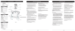
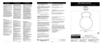
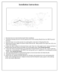
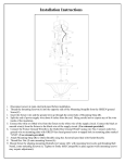
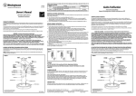
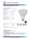
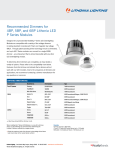
INSTALLATION FIGURES
FIGURES D’INSTALLATION
REQUIRED TOOLS
HERRAMIENTAS REQUERIDAS
OUTILS REQUIS
FIGURAS DE LA INSTALACIÓN
1. Remove fixture components and parts pack(s). Check
that all parts are included. See page 2.
Warning: Safely dispose of packaging materials.
Troub le Shooting Guide
If this fixture fails to operate properly, use the guide below
to diagnose and correct the problem.
Assistance may be required to support fixture during
installation.
Verify that fixture is wired properly.
Verify that fixture is grounded correctly.
The line voltage at the fixture is correct.
2. Thread two 1.5" Screws (2) about ¼" into junction box.
See Fig 2.
FIXTURE PARTS LIST
Description
Quantity
1)Diffuser ...................................... 1
2)Screw #8-32 x 1.5"* ..................... 2
3)Fixture ........................................ 1
4)Wirenuts* .................................... 3
5)Diffuser Latches ........................... 2
Assistance may be required to support fixture during
installation.
WIRING AND FIXTURE OPERATION CAUTION:
Connect fixture to supply wires rated for at least 90°C (194°F).
Do not use fixture on dimming circuits.
NOTE: Turn off power at fuse or circuit breaker box!
*Contained in Part Packs
Mounting Hardware Included
Figure 1
LISTA DE EMBALAJE
Descripción
Cantidad
1)Difusor ......................................... 1
2)Tornillos #8-32 x 1.5"* ................. 2
3)Carcasa ...................................... 1
4)Capuchones de Alambres* ......... 3
5) Aldaba del Difusor ....................... 2
3. Ground fixture by lifting Fixture Housing (3) to junction
box and connect the bare copper ground wire from the
junction box and the green ground wire from the fixture with
a wire nut (4). See Fig 2.
4. Use Wirenuts (4) to connect the black fixture wire to the
black power supply wire and the white (neutral) fixture wire
to the white power supply wire. See Fig 2.
FOR PROPER CONNECTION, PLACE WIRENUT OVER
WIRES, TWIST CLOCKWISE UNTIL TIGHT.
Note: Make sure no wires are exposed.
5. Hold Fixture Housing (3) in one hand and with the other
hand position wires up into junction box.
6. Position Fixture Housing over junction box, aligning
keyholes in Fixture Housing with two Screws (2) previously
mounted to the junction box. Rotate the fixture housing to
locate the Screws in the slots and tighten Screws to secure
the housing against ceiling. See Fig 2.
*Contenido en el Paquete de Piezas
Herraje para Montaje Incluidas
If further assistance is required, contact:
Technical Support at: (800) 748-5070
This LED light provides low maintenance service with no
bulbs to change.
Cleaning Diffuser: For best results, diffusers should be
washed with soap or mild detergent. Rinse with clear water and allow to air dry.
LISTE DES PIECES
1. Remueva los componentes del luminario y paquete(s) de
pieza(s). Asegure que todas las piezas estén incluidas.
Vea la Pagina 2.
Advertencia: Para seguridad deseche los materiales de
embalaje.
Suggested Dimmers
This fixture is designed to operate with most standard Triac Based
(Forward Phase-Control or Leading Edge) dimmer and is not
compatible with 0-10v dimming systems.
Noted below is a listed of dimmers that have been tested with this
fixture. This list of dimmers does not imply any guarantee or
warranty of compatibility with a particular application.
Dimmers that are not listed do not imply non-compatibility.
Lutron: DVELV 300P, Skylark 300P, NTELV 300, NLV 600
Leviton: 6633P, IPL06, 6674P, IPE04, Tramatron 600W
Synergy: ISD 600 I 120
Puede que necesite ayuda a sostener el luminario durante la
instalación.
CUIDADO DE LA OPERACIÓN DEL LUMINARIO Y EL
ALAMBRADO: Conecte el luminario a alambres de
suministros que estén clasificados a por lo menos 90°C
(194° F). No use el luminario en circuitos con atenuador de
intensidad. Consulte a un electricista calificado para asegurar
la clasificación adecuada del alambre de suministro.
CUIDADO DEl ALAMBRADO Y OPERACION DEL LUMINARIO:
Conecte luminario a los alambres de suministros alambres
clasificados a por lo menos 90°C (194°F). No use el luminario
en circuitos con atenuador de intensidad.
3. Accesorio de tierra levantando Fixture Vivienda (3) a la caja de
conexiones y conecte el cable a tierra de cobre desnudo de la caja y
el alambre verde de tierra del aparato con una tuerca para cable
Vea Fig. 2
4. Use Capuchones de Alambres para conectar el alambre
negro de la luminaria al alambre negro suplidor de electricidad
y el alambre blanco (neutral) de la luminaria al alambre blanco
suplidor de electricidad. Vea Fig. 2.
PARA UNA CONEXIÓN APROPIADA, COLOQUE EL
CAPUCHÓN DE ALAMBRES SOBRE LOS ALAMBRES, GIRE
HACIA SU DERECHA HASTA QUE ESTE APRETADO.
5.Sostenga la caja de la luminaria en una mano y coloque los
alambres dentro de la caja de ensambladura con la otra mano.
6. Coloque caja de la luminaria sobre la caja de
ensambladura alineando los agujeros de la caja de la
luminaria con los tornillos que extienden de la barra transversal previamente montados a la caja de ensambladura. Gire la
caja de la luminaria hasta localizar los tornillos en las ranuras
y apriete los tornillos para asegurar la caja de la luminaria
contra el techo.
Vea Fig. 2.
8. Turn on electricity at fuse or circuit breaker box and verify
success of installation.
4
7. Para instalar el Difusor, afloje los (3) tornillos
manuales en el perímetro de la caja de la luminaria.
Levante el difusor en posición y asegure apretando los
tornillos manuales. Vea Fig. 1.
8. Encienda la electricidad en la caja de fusible o la
caja de cortacircuito y verifique el éxito de la instalación.
2. Enrosque (2) tornillos de 1.5" como ¼" dentro de la barra
transversal. Vea Fig. 2
Nota: ¡Apague la electricidad en la caja de cortacircuitos o de
fusibles!
7. To install Diffuser (1), loosen Thumb Screws (5) on
perimeter of housing. Lift Diffuser in position and secure by
tightening Thumb Screws. See Fig 1.
Description
Quantité
1) Diffuseur ...................................... 1
2) Vis #8-32 x 1.5"* .......................... 2
3) Boîtier .......................................... 1
4) Serre-fils* ..................................... 3
5) Fermoir du diffuseur ................... 2
GUÍA DE
DE PASO-A-PASO
GUÍA
PASO-A-PASO
INSTALLATION
INSTALLATION INSTRUCTIONS
- ENGLISH INSTRUCTIONS
Guía de Localización de Averías
Si este luminario falla de operar apropiadamente, use la
siguiente guía para diagnosticar y corregir el problema.
Verifique que el luminario este alambrado apropiadamente.
Verifique que el luminario este conectado tierra
correctamente.
El voltaje de la línea en el luminario este correcto
Si requere ayuda adicional, contacte:
Technical Support: (800) 748-5070.
Esta lámpara LED con detector de movimiento necesita
muy poco mantenimiento y no es necesario cambiar los
focos.
COMO LIMPIAR EL ACRILICO:
Para mayor resultado,
difusor de acrilico se debe lavar con jabon o detergents
suaves. Enjuague con agua y deje secar al aire.
Reductores de alumbrado recomendados
Este montaje se diseñó para operar con la mayoría de los
reductores de alumbrado con triac estándares (control de fase
directa o borde de ataque) y no es compatible con los sistemas
de reducción de luz de entre 0 y 10 v.A continuación se enumera
una serie de reductores de alumbrado que han sido probados
con este montaje. No se garantiza la compatibilidad de este
listado de reductores de alumbrado con ninguna aplicación en
particular.Los reductores de alumbrado que no se incluyen en la
lista no son necesariamente incompatibles.
Lutron: DVELV 300P, Skylark 300P, NTELV 300, NLV 600
Leviton: 6633P, IPL06, 6674P, IPE04, Tramatron 600W
Synergy: ISD 600 I 120
*Compris dans les sacs d’emballage
Figure 2
Quincaillerie de Montage Incluses
Page 2
Page 4
Page 5