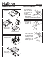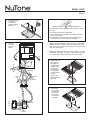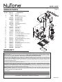
1
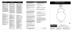
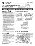
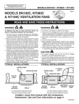
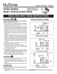
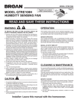
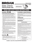
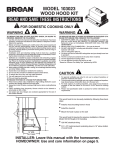
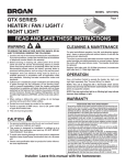
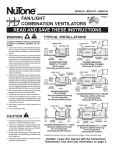
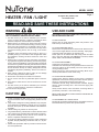
model 665RP
Heater / fan / light
To register this product, visit:
www.nutone.com
Page read and save these instructions
warning
USE AND CARE
to reduce the risk of fire, electric shock, or injury to persons, observe the following:
1. Use this unit only in the manner intended by the manufacturer. If you have questions, contact the manufacturer at the
address or telephone number listed in the warranty.
2. Before servicing or cleaning unit, switch power off at service
panel and lock the service disconnecting means to prevent
power from being switched on accidentally. When the service disconnecting means cannot be locked, securely fasten
a prominent warning device, such as a tag, to the service
panel.
3. Installation work and electrical wiring must be done by a
qualified person(s) in accordance with all applicable codes
and standards, including fire-rated construction codes and
standards.
4. Sufficient air is needed for proper combustion and exhausting of gases through the flue (chimney) of fuel burning equipment to prevent backdrafting. Follow the heating equipment
manufacturer’s guideline and safety standards such as those
published by the National Fire Protection Association (NFPA),
and the American Society for Heating, Refrigeration and Air
Conditioning Engineers (ASHRAE), and the local code authorities.
5. When cutting or drilling into wall or ceiling, do not damage
electrical wiring and other hidden utilities.
6. Ducted fans must always be vented to the outdoors.
7. Do not use this unit with any solid-state speed control device.
8. Never place a switch where it can be reached from a tub or
shower.
9. Use this unit only in the manner intended by the manufacturer. If you have questions, contact the manufacturer.
10. This unit must be grounded.
DISCONNECT ELECTRIC POWER SUPPLY BEFORE CLEANING OR SERVICING THIS UNIT.
caution
1. Provide a separate 20 AMP circuit. Use 12 GA. power cable
of type which meets code. Use supply wiring rated for at least
90OC.
2. This product is designed for ceiling installation only. This product is designed for installation in ceilings up to a 12/12 pitch.
Ductwork must point up. DO NOT MOUNT THIS PRODUCT
IN A WALL.
3. Install in ceiling only, at least 12” from any wall.
4. For greatest efficiency, install heater so heat is directed toward
tub or shower area. Avoid directing toward walls or windows.
5. For general ventilating use only. Do not use to exhaust hazardous or explosive materials and vapors.
6. To avoid motor bearing damage and noisy and/or unbalanced
impellers, keep drywall spray, construction dust, etc., off power unit.
7. Please read specification label on product for further information and requirements.
TO REPLACE BULB:
Remove lens by gently depressing sides and pull down. Use
bulb rated up to 100 watts only.
TO CLEAN LENS AND GRILLE:
Remove lens as explained above. Remove bulb. Remove acorn
nut in center of light reflector and lower assembly. Unplug light.
CAUTION: Grille and reflector are separate units.
Plastic parts can be cleaned with mild, soapy water and dried
with a soft cloth. DO NOT USE ABRASIVE CLOTHS, STEEL
WOOL PADS, OR SCOURING POWDERS.
TO CLEAN FAN ASSEMBLY:
Unplug fan motor. Remove retaining screws.
CAUTION: Fan assembly will swing downward when screws are
removed. Support the fan assembly with a free hand while removing retaining screws.
Gently vacuum fan, motor and interior of housing. Motor is permanently lubricated and never needs oiling.
TO CLEAN HEATER ASSEMBLY:
Unplug heater. Remove retaining screw. Place a screwdriver
tip between outer wall of housing and heater exhaust opening.
Gently pry outward until exhaust housing slips out.
CAUTION: Unit will swing downward when released. Support
with the heater assembly with a free hand while prying with
screwdriver.
Gently vacuum blower, motor and interior of housing. Motor is
permanently lubricated - never needs oiling.
METAL AND ELECTRICAL PARTS SHOULD NEVER BE IMMERSED IN WATER.
TO REASSEMBLE ALL ABOVE PARTS:
Reverse all procedures explained above. Assemblies should not
be disassembled any further than explained above.
model 665RP
prepare the unit
install the unit
Page For best results, choose a
location which allows fan
to be vented outside with
the shortest possible duct
run and the fewest number of elbows.
1. Remove the lamp
holder assembly.
1. Position unit between
joists and extend mounting brackets. Position
brackets such that the
bottom edge of housing will be flush with finished ceiling.
Mark the top of keyhole slot on all four mounting brackets.
2. Remove unit temporarily, and pound
nails partially into
joists at all four
marked locations.
2. Remove the heater
assembly retaining
screw.
3. Rotate heater assembly
and lift it up and out of the
housing.
4. Remove fan assembly
retaining screws. Lift
fan assembly out of the
housing.
5. Slide the 4 hanger
bars into the slots
on each end of the
housing - 2 hanger
bars per side.
3. Hang unit from nails and
check if unit will be flush with
finished ceiling. Pound nails
tight. For wide joist centers: A #8 x 3/8 self-tapping screw
can be used to join extended
brackets together and create a rigid mount. To ensure
a noise-free mount, crimp
the bracket channels tightly
around mounting brackets.
model 665RP
Page 4. Use a flat-bladed
screwdriver
to remove the
proper electrical
knockouts.
wire opening
release slot
If the switch has not been wired properly and wires need to
be moved:
1. Each wire opening has a release slot.
2. Push a small nail or screwdriver into release slot while
gently removing wire.
3. DO NOT pull any wire out of the switch without using
the release slot. The switch may be damaged.
5. Connect
electrical
wiring as
shown.
6. Replace the fan assembly removed in Step 4, under “PREPARE THE UNIT” on Page 2. Plug fan assembly into receptacle (C) on the the side of the wiring cover. Direct wires
away from blower inlets.
7. Replace the heater assembly removed in Steps 2, 3, under
“PREPARE THE UNIT” on Page 2. Plug heater assembly
into receptacle (A). Direct wires away from blower inlets.
LIGHT
HEAT
A
B
C
RED
A
8. Install grille and
light reflector.
Plug light into
receptacle (B).
Tighten acorn
nut securely.
Be careful not
to overtighten
nut and deform
reflector.
VENT
C
B
3 WHITE WIRES
RED
2 WHITE
WIRES
BLUE
BLACK
3 GROUND WIRES
Install a 100
Watt (maximum)
light bulb.
BLACK
9. Install light
lens. Gently
squeeze tabs
on lens and
insert them
into the slots
in the grille.
RED
HEAT
3 WHITE WIRES
VENT
LIGHT
BLACK
3 GROUND
WIRES
120 VAC LINE IN
model 665RP
KEY NO. PART NO.DESCRIPTION
1
97017451
Housing
2
30652
Damper
3
44388
Mounting Bracket (4 Req.)
4
99270981
Receptacle, White
99270982
Receptacle, Black
99270489
Receptacle, Red
5
82403
Fan Blower Wheel
6
99080592
Fan Motor
7
97017080
Fan Motor Plate Assembly
8
99260428
Nut (4 Req.)
9
89760
Grille
10
98010306
Light Reflector
11
97005316
Acorn Nut
12
99770112
Light Socket
13
53740
Light Lens
14
97005058
Bolt Assembly
15
99020134
Heater Blower Wheel
16
99150576
#8 x 3/8 Sheet Metal Screw (2 Req.)
17
93260457
#10 - 32 Nut (7 Req.)
(2 included in Key No. 16)
18
99270107
Heater Hooks (5 Req.)
19
99150576
#8 x 3/8 Sheet Metal Screw (4 Req.)
20
98010295
Heater Scroll Cover
21
97017070
Heater Scroll Housing
22
99080593
Heater Motor
23
99150576
#8 x 3/8 Sheet Metal Screw (3 Req.)
24
98004514
Heater Element
25
99260512
Tinnerman Nut
26
99420666
Wire Clip (2 Req.)
27
98010298
Scroll Band
Page 2
service parts
3
1
26
25
4
10
20
27
22
21
19
11
5
12
6
15
18
16
24
7
14
23
8
17
9
13
warranty
One Year Limited Warranty
WARRANTY OWNER: Broan-NuTone warrants to the original consumer purchaser of its products that such products will be free from defects in materials or
workmanship for a period of one (1) year from the date of original purchase. THERE ARE NO OTHER WARRANTIES, EXPRESS OR IMPLIED, INCLUDING,
BUT NOT LIMITED TO, IMPLIED WARRANTIES OF MERCHANTABILITY OR FITNESS FOR A PARTICULAR PURPOSE.
During this one year period, Broan-NuTone will, at its option, repair or replace, without charge, any product or part which is found to be defective under
normal use and service. THIS WARRANTY DOES NOT EXTEND TO FLUORESCENT LAMP STARTERS OR TUBES, FILTERS, DUCT, ROOF CAPS, WALL
CAPS AND OTHER ACCESSORIES FOR DUCTING. This warranty does not cover (a) normal maintenance and service or (b) any products or parts which
have been subject to misuse, negligence, accident, improper maintenance or repair (other than by Broan-NuTone), faulty installation or installation contrary
to recommended installation instructions.
The duration of any implied warranty is limited to the one year period as specified for the express warranty. Some states do not allow limitation on how long
an implied warranty lasts, so the above limitation may not apply to you.
Broan-NuTone’S OBLIGATION TO REPAIR OR REPLACE, AT Broan-NuTone’S OPTION, SHALL BE THE PURCHASER’S SOLE AND EXCLUSIVE REMEDY UNDER THIS WARRANTY. Broan-NuTone SHALL NOT BE LIABLE FOR INCIDENTAL, CONSEQUENTIAL OR SPECIAL DAMAGES
ARISING OUT OF OR IN CONNECTION WITH PRODUCT USE OR PERFORMANCE. Some states do not allow the exclusion or limitation of incidental or
consequential damages, so the above limitation or exclusion may not apply to you. This warranty gives you specific legal rights, and you may also have other
rights, which vary from state to state. This warranty supersedes all prior warranties.
WARRANTY SERVICE: To qualify for warranty service, you must (a) notify Broan-NuTone at the address or telephone number below, (b) give the
model number and part identification and (c) describe the nature of any defect in the product or part. At the time of requesting warranty service,
you must present evidence of the original purchase date.
Date of Installation
Builder or Installer
Model No. and Product Description
IF YOU NEED ASSISTANCE OR SERVICE - CONTACT:
Broan-NuTone LLC Hartford, Wisconsin www.nutone.com 888-336-3948
Rev. 08/2007
99043912E