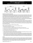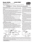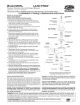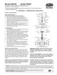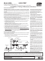
1
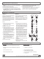
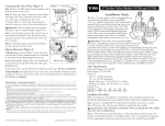
Model 420XL Pressure Vacuum Breaker (3/4" & 1") LEAD-FREE* ® *This product contains a weighted average lead content less than 0.25% for wetted surfaces. Installation Testing Maintenance Instructions INSTALLATION INSTRUCTIONS CAUTION: Installation of Pressure Vacuum breakers must be performed by qualified, licensed personnel. Faulty installation could result in an improperly functioning device. The installer should be sure the proper device has been selected for the particular installation. ZURN WILKINS Model 420XL Pressure Vacuum Breakers are for use on potable water lines where a health hazard could exist if a backsiphonage situation were to occur. They must not be installed where backpressure may occur. Proper performance depends upon following these installation instructions and prevailing governmental and industry standards and codes. Failure to do so releases ZURN WILKINS of any liability that it might otherwise have with respect to that device. Such failure could also result in an improperly functioning device. 1.Before installing the ZURN WILKINS Model 420XL Pressure Vacuum Breaker, flush the lines thoroughly to remove all debris, chips and other foreign matter. 2. The Model 420XL must be installed in a vertical position (see Fig. 1) to provide prop er operation of the air inlet valve. 3.Provide adequate space around the installed unit so that the test cocks will be accessible for testing and servicing. 4.CAUTION: If installation of a Model 420XL unit is in a building, provide a suitable drain arrangement to drain off spillage from the air vent. 5. Install valve at least 12 inches above the highest piping or water outlet down stream of the Model 420XL Pressure Vacuum Breaker. 6.Always consult local codes for installation methods, approvals and guidance. 7. The Model 420XL Pressure Vacuum Breaker may be installed outdoors only if the device is protected against any freezing conditions. Warning: Do not block air vent opening with insulation. Exposure to freezing conditions will result in improper function or damage to the device. The installation location must be kept above 32°F. PLACING THE DEVICE IN SERVICE After the installation of a Model 420XL Pressure Vacuum Breaker has been completed, place the unit in service as follows: 1. Start with both shut-off valves closed. Open the inlet shut-off valve until the Pressure Vacuum Breaker is completely pressurized. 2. A brief discharge from the air vent may occur while the device is pressurizing. INLET SHUT-OFF VALVE (3) TESTCOCKS (4) WILKINS 420 PVB 1” OUTLET SHUT-OFF VALVE (5) OUTLET DRAIN VALVE (6) 12" MIN. ABOVE HIGHEST OUTLET MAIN SHUT-OFF VALVE (1) INLET DRAIN VALVE (2) (IF ALLOWED BY LOCAL CODES) DIRECTION OF FLOW DRAIN Fig. 1 The discharge should cease by the time the shut-off valve is in the full open position. 3.If the discharge does not stop, refer to "MAINTENANCE INSTRUCTIONS". Repressurize device as in Step 1. Device should function properly. 4.Slowly open the No. 2 shut-off valve. The Model 420XL is now in service. 5.After the Model 420XL has been properly installed, test the device. If the device fails the test, refer to "MAINTENANCE INSTRUCTIONS". Drain Procedure for Freeze Protection 1. Turn off main shut-off (1) that supplies water to the system. 2. Open both inlet and outlet drain valves in the system (2 & 6). Open inlet and outlet shut-off valves on the pressure vacuum breaker (3 & 5) and all of the test cocks. Leave all valves and test cocks in the half open/half closed (45°) position to allow full drainage of the ball valves and test cocks. 3. If you with to "blow out" the system downstream of the pressure vacuum breaker, make sure the outlet drain valve (6) is open and the pressure vacuum breaker shut-off valve (5) is closed. 4. Connect an air hose to the outlet drain valve (6) and inject an adequate volume of air to remove all water from the downstream portion of the system. 5. CAUTION: Open outlet shut-off valve to the pressure vacuum breaker (5) and outlet drain valve (6) to the half open/half closed (45°) position after "blow out" process is completed. 6. If drain valves (2 & 6) are not part of the system, and if air pressure is not used to "blow out" the system, the internal components of the pressure vacuum breaker should be removed for the duration of the winter. 7. Leave all drain valves (2 & 6), shut-off valves (3 & 5) and test cocks in the half open/half closed position (45°) for the duration of the winter to prevent freezing. CAUTION: Be certain that main shut-off (1) remains tightly closed to prevent refilling of the system. Also, the main shut-off valve must be resilient seated to insure no leakage of water into the system. WARRANTY: ZURN WILKINS Valves are guaranteed against defects of material or workmanship when used for the services recommended. If in any recommended service, a defect develops due to material or workmanship, and the device is returned, freight prepaid, to ZURN WILKINS within 12 months from date of purchase, it will be repaired or replaced free of charge. ZURN WILKINS' liability shall be limited to our agreement to repair or replace the valve only. Proposition 65 Warning This product contains chemicals known to the State of California to cause cancer or birth defects or other reproductive harm. ® www.zurn.com 1 Maintenance Instructions 1.Close inlet and outlet shut-off valves before disassembling device. 2.Remove canopy screw and canopy. 3.Bleed off pressure by opening the No. 2 test cock. 4.Unscrew the bonnet from the body by turning counterclock- wise. CAUTION: Apply force at the outside edge of bonnets. DO NOT use wrench or screwdriver on top of bonnet or float guides, damage can result. 5.Remove the float assembly, spring retainer, spring and spider. The seat and seat o-ring may now be removed. 6.Clean all parts with clean water only. 7.After completing inspection, replace necessary parts and re- assemble. Repair kits are available from your supplier. 8.Retest according to "TESTING PROCEDURES". Testing Procedures TEST NO. 1 TEST NO. 2 Purpose: To test the opening pressure differential of the air inlet valve. Requirement: The air inlet valve shall open when the pressure in the body is more than 1.0 psi above atmospheric pressure. The air inlet valve shall be fully open when the water drains from the body. Purpose: To test the check valve for tightness in the direction of flow. Requirement: The check valve shall be drip-tight in the normal direction of flow when the inlet pressure is at least 1.0 psi and the outlet pressure is atmospheric. CANOPY SCREW CANOPY BONNET O-RING RELIEF VALVE ASSEMBLY AIR INLET DISC STEPS: STEPS: 1. Bleed water through both test cocks to eliminate foreign material. 2.Install appropriate fittings for test kit hoses. 3.Remove air inlet canopy. 4.Install the high side hose of the diffe rential pressure gauge to test cock #2. Open test cock #2 and bleed air from hose and gauge by opening the high side bleed needle valve. Close the high side bleed needle valve. 5.Close outlet shut-off valve then close inlet shut-off valve. 6.Slowly open the high side bleed needle valve being especially careful not to drop the pressure differential too fast. Record the pressure differential at which the air inlet valve opens. 7.Close test cock #2 and remove equip- ment. 8.Open inlet shut-off valve. 1. Attach high side hose of the differential pressure gauge to test cock #1. Open test cock #1 and bleed all air from the hose and the gauge by opening the high side bleed needle valve. Close the high side bleed needle valve. 2.Close inlet shut-off valve. 3.Open test cock #2. The air inlet valve will open and the water in the body will drain out through test cock #2. When this flow of water stops, the differential pressure indicated by the gauge after it has settled will be the pressure drop across the check valve. This value must be 1.0 psi or greater. Record this value. If water continues to flow out of test cock #2, then the inlet shut-off valve is leaking. 4.Close test cocks #1 and #2 and remove equipment. 5.Replace air inlet canopy. 6.Open inlet shut-off valve, then outlet shut-off valve. FLOAT SPRING RETAINER CHECK SPRING POPPET SEAL RING SEAT OUTLET SHUTOFF VALVE OUTLET SHUTOFF VALVE O-RING O-RING TEST COCK #2 TEST COCK #2 BODY TEST COCK #1 TEST COCK #1 INLET SHUTOFF VALVE 3/4" SIZE 1" SIZE Troubleshooting PROBLEM Air inlet valve does not open as gauge drops to 0.0 psid. Air inlet valve does not open and differential on gauge will not drop. POSSIBLE CAUSES 1. Air inlet disc stuck to seat. Air inlet opens below 1.0 psid. 1. Dirty or damaged air inlet disc. 2. Scale buildup on disc or bonnet. Check valve opens below 1.0 psid. 1. Dirty or damaged check disc or seat o-ring. 2. Damaged seat. ® IS420XL (REV. 4/13) 1. Leaking No. 1 shut-off valve. ZURN WILKINS 1747 Commerce Way, Paso Robles, CA 93446 Phone:855-663-9876 Fax:805-238-5766 www.zurn.com 2