1
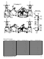
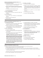
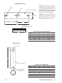
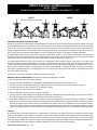
FEBCO Operation and Maintenance
805YD / 806YD
Double Check and Double Check Detector Assembly (21/2" – 10")
805YD
806YD
(Shown with OS&Y Shut-offs)
FEATURES AND OPERATING PROCEDURES
This device consists of two independently operating poppet type check valves. Each check valve is spring loaded to maintain a minimum
of 1 PSIG differential pressure across the check in a no-flow condition. In a normal flow condition the checks open an amount corresponding to the flow rate. During a backflow (backpressure) situation the seat discs close and seal to prevent any flow reversal. Sizes 21/2"
through 10" (805YD) include two spring loaded Y-pattern check valves with epoxy coated ductile iron bodies and bronze trim, two cast iron
shut-off valves and four testcocks for field testing. All valves are flanged type and the unit is shipped completely assembled.
The Model 806YD device consists of a mainline double check valve with a metered 3/4" by-pass double check valve connected around
the mainline checks. The mainline pressure drop is slightly higher than the by-pass, thus all small flow up to the crossover point (approx.
9 GPM) is through the by-pass. Above the crossover point flow is through the mainline and the by-pass.
The FEBCO 806YD Device main line unit consists of two independent, spring loaded, Y-pattern check valves, two shutoff valves
and four testcocks. The spring loaded poppets in conjunction with soft elastomer discs provide drip tight closure against backflow. The
Y-pattern valve design provides low pressure loss at the high flow rates. The shutoff valves are OS&Y type, UL listed for fireline service.
The by-pass line assembly consists of a water meter in series with a Model 805YB 3/4" double check valve. The meter is the total type
with accurate registration between 1 and 20 gpm flow rates. The static pressure drop across both checks is approximately 2 PSI less
than the mainline check valves.
Consult local codes before installing any Backflow Prevention assembly.
GENERAL SERVICE PROCEDURES (General service instructions applicable to all sizes.)
1. Rinse all parts with clean water prior to assembly.
2. DO NOT USE ANY PIPE DOPE, OIL, GREASE OR SOLVENT ON ANY PARTS unless instructed to do so.
4. Do not force parts. Parts should fit freely together. Excess force may cause damage and render the device inoperable.
5. Carefully inspect seals, seating surfaces, etc. for damage or debris.
5. Test unit after servicing to insure proper operations.
6. Refer to applicable parts list and figures for more information.
7. A table on the back page provides size and material information for standard parts (non-special design). These parts can usually be
purchased locally from parts distributors, rather than special order from the factory.
8. Some water conditions can cause a buildup of calcium or similar material deposits on some moving parts. Normally this condition
would not occur on devices used in systems with varying flow rates. The scraping action of moving parts helps to remove any deposits.
However, with devices used on static systems such as firelines, any deposits would not be scraped away and could interfere with the
check valve operation. Devices in these applications should be disassembled and inspected on a periodic basis depending on water
quality. Any deposits should be removed from the center guiding stem and bushings. Use care to avoid damage to guiding surfaces.
TESTING
All mechanical devices should be inspected on a regular basis to ensure they are working correctly. The assembly should be tested
at time of initial installation, after servicing or maintenance, and at least annually thereafter. Acceptable test procedures are published by
Foundation for Cross Connection Control and Hydraulic Research at the University of Southern California (USC), The American Water
Works Association (AWWA), The American Society of Sanitary Engineering (ASSE Series 5000) and the Canadian Standards Association (CAN/CSA B64•10). Please consult the regulatory authority in your area for more specific information.
FEBCO Model 805YD & 806YD (21/2" - 10")
Page 1
TROUBLE SHOOTING GUIDE
Symptom #1
Cause:
Solution:
Check fails to hold 1.0 PSID min.
A. Debris on sealing surfaces
Disassemble and clean
B. Leaking shut-off valve
Disassemble and clean or repair
C. Damaged seat disc or seat ring
Disassemble and replace
D. Damaged guide holding check open
Disassemble and replace guide pin
and/or sleeve bushing
E. Weak or broken spring
Disassemble and replace spring
Symptom #2
Cause:
Solution:
Chatter during flow conditions.
A. Worn or damaged guide
Disassemble & repair or replace guide
Symptom #3
Cause:
Solution:
Low flows passing through the
mainline valve (806YD only).
A. Mainline check fouled
Disassemble and clean
B. Meter strainer plugged
Disassemble and clean
C. Damaged mainline seat disc or seat
Disassemble and replace
D. Broken mainline spring
Disassemble and replace
HOW TO ORDER REPAIR KITS
1. Locate item number and kit number in this maintenance manual.
2. Verify the size of the valve the parts are to be used for.
3. Provide full model number located on I.D. plate.
4. Record kit number.
5. A serial number (located on the I.D. plate) will assist in ordering the proper kits.
6. Contact your local FEBCO Parts Distributor.
REPAIR KITS
805YD/806YD Assemblies/Kits
21/2"
3"
4"
6"
8"
10"
Model 805YD Spring Assembly
(Items: 3. 4.1, 5, 6, 7, 7.1, 7.2, 9, 11, 15, 50)
905-086
905-088
905-467
902-469
902-471
902-473
Model 805YD/806YD Rubber Parts
(Items: 11, 14, 50)
905-059
905-060
905-061
905062
905-063
905-064
902-386YD
902-385YD
902-384YD
902-383YD
902-382YD
902-381YD
Model 805YD/806YD Lg. Mounting Kit
(Items: 16, 17, 17.1; Both Ends)
905-036
905-037
905-038
905-039
905-040
905-041
Model 805YD/806YD Cover Assembly
(Items: 4, 4.1, 14, Aircock (not shown)
902-497
902-498
902-499
902-500
902-501
902-502
Model 806YD Spring Assembly
(Items: 3, 4.1, 5, 6, 7, 7.1, 7.2, 9, 11, 15, 50)
-
-
902-514
902-515
902-516
902-517
Model 806YD By-Pass Kit (without meter)
(Items: 301 through 313)
-
905-138
905-138
905-138
905-138
905-138
Description
Model 805YD/806YD Seat Kit
(Items: 2, 2.1, 2.2, 12)
Page 2
FEBCO Model 805YD & 806YD (21/2" - 10")
MODEL 805YD / 806YD
Cut-a-Way
13
4
14
4.1
9
5
11
2.3
10.4 2.4
41.1
3
7.2
7.1
17.4
MODEL 806YD
By-Pass Assembly
Vertical Pipe
304
305.1
311
40 41
42 16
17 17.1
7 2.1 15 6 12.1 2 50 1
306
302
312
313
309
308
300
305.1
308
309
307.1
303
305.1
301.1
311
311
MODEL 805YD/806YD PARTS
Fig No.
1
2
2.1
2.3
2.4
3
4
4.1
5
6
7
7.1
7.2
9
11
Description (QTY)
Body (1)
Seat Ring (1)
Bushing (1)
Washer (6)
Capscrew (6)
Guide (2)
Cover (4)
Bushing (2)
Disc Holder (2)
Disc Washer (2)
Stem (2)
Screw (2)
Washer (2)
Spring (2)
Seat Disc (2)
FEBCO Model 805YD & 806YD (21/2" - 10")
Fig No.
12.1
13
14
15
16
17
17.1
17.4
40
41
41.1
50
42
42
Description (QTY)
O-Ring (2)
Capscrew (16)
O-Ring (2)
Hex Nut (2)
Gasket (1)
Capscrew (4)
Hex Nut (12)
Lift Strap (2)
Ball Valve (3)
Nipple (1)
Nipple (2)
O-Ring (2)
NRS Gate Valve
OS&Y Gate Valve
Fig No.
Description (QTY)
300**
Meter
301**
Nipple
302**
Ball Valve
303**
Ball Valve
301.1**
Testcock
304**
Elbow
305**
Nipple
306**
Nipple
307.1**
Tailpiece
308**
Coupling Nut
309**
Meter Washer
311**
Nipple
312**
805Y (Less Shutoff's)
313**
Coupling
** Used in the Model 806YD only.
Page 3
MODEL 805YD/806YD COMMERICAL PARTS
Item
Description
Material
21/2"
3"
7.1
Screw
Brass
-
-
12
O-Ring
Buna-N
568-238
31/2 x3 3/4x1/8
568-246
41/2 x4 3/4x1/8
568-254
51/2 x5 3/4x1/8
568-264
71/2 x7 3/4x1/8
7
7
1
5
3
3
13
Cap Screw
SS
14
O-Ring
Buna-N
15
Lock-Nut
Brass
17
Bolt & Nut
Steel
40
Ball Valve
Brass
51
O-Ring
Buna-N
/16 -14 x 1
Nipple
o
6"
3
3
/8-16 x 1 1/2
/2 -13 x 11/4
/16 -14 x 1
8"
3
/8-16 x 2
3
/8-16 x 2
568-273
91/2 x10x1/8
/8 -11 x 11/2
10"
/8-16 x 2
105/16 x109/16x1/8
/4 -10 x 11/2
/4 -10 x 13/4
568-244
41/4 x4 1/2x1/8
568-252
51/4 x5 1/2x1/8
568-263
71/4 x7 1/2x1/8
568-272
91/2 x9 3/4x1/8
568-451
11x111/2x1/4
123/4 x13x1/8
3
/8 -24
Elastic
3
/8 -24
Elastic
3
/4 -16
Elastic
3
/4 -16
Elastic
7
/8 -14
Elastic
7
/8 -14
Elastic
5
/8 -11 x 21/4
1
/2 IPS 200#
568-014
/2 x 5/8 x 1/16
1
41**
4"
5
/8 -11 x 21/2
1
/2 IPS 200#
568-014
/2 x 5/8 x 1/16
1
Bronze
-
-
5
/8 -11 x 23/4
1
/2 IPS 200#
3
568-116
/4 x 15/16 x 1/16
1
/2 x Close
3
3
/4 IPS 200#
3
568-116
/4 x 15/16 x 1/16
3
/4 x Close
1
62**
90 Elbow
Bronze
-
-
63**
Tee
Bronze
-
-
64**
Nipple
Bronze
-
-
1
65**
Bushing
Bronze
-
-
1
66**
Nipple
Bronze
-
-
/2 x 1/2 x 1/2
3
/4 IPS 200#
7
568-118
/8 x 11/16 x 3/32
3
/4 x Close
3
/4 x 3/4 x 3/4
3
/4 IPS 200#
7
568-118
/8 x 11/16 x 3/32
3
/4 x Close
3
/4
3
/4 x 3/4 x 3/4
-
3
/4 x 6
3
/4 x 6
3
/8 -9 x 31/2
/2
3
/2 x 3/4
7
1
/2
/2 x 5
-
/4 -10 x 31/4
1
/2
1
3
/4 -10 x 3
/4 x 6
-
/4 x 21/2
3
/4 x 21/2
3
/4 x 21/2
** Used in the Model 806YD only.
These parts are commercially available through most hardware distributors or retailers. Shut-off valves, testcocks, flange gaskets,
etc., are also commercially available but not listed. The water meter is a 5/8 x 3/4 size. Several brands are USC approved for use on
the Model 806YD. Contact the factory for additional information.
WARRANTY
All products manufactured and sold by CMB Industries, Inc. carry with them the following warranty: CMB Industries, Inc. warrants to the
original purchaser (who is the end user) all products manufactured by it will be free from defects in workmanship and material for a
period of one (1) year from the date of original shipment.
CMB Industries, Inc. also warrants that all internal components of 1/2" through 2" Model 850/860 and 1/2" through 1" Model 766 products,
will be free from defects in workmanship and material for a period of five (5) years from the date of original shipment and also that the
body only of the 1/2" through 11/4" Model 765 will be subject to a lifetime warranty against damage by freezing.
This warranty is applicable provided such products are used under normal conditions within the recognized pressure, flow and
temperature limits and are given normal service and care. CMB INDUSTRIES, INC. MAKES NO OTHER REPRESENTATION OR
WARRANTY OF ANY KIND, EXPRESSED OR IMPLIED, IN FACT OR IN LAW, AND EXPRESSLY DISCLAIMS ALL OTHER WARRANTIES, INCLUDING WITHOUT LIMITATION, THE WARRANTIES OF MERCHANTABILITY OR FITNESS FOR PARTICULAR PURPOSE.
In the event of a defect in material or workmanship of a product covered by this warranty, CMB Industries, Inc. shall, at its sole option,
repair or replace such defective product. CMB Industries, Inc. shall not be liable for any labor required to repair or replace any product
covered by this warranty. This warranty is void with respect to any such product which is altered or tampered with by anyone
without prior consent of CMB Industries, Inc. CMB Industries, Inc. shall not be liable under any circumstances for damages caused by
accident, misuse or abuse of the product or for failure to follow the installation, maintenance or operating instructions. IN NO EVENT
SHALL CMB INDUSTRIES BE LIABLE FOR CONSEQUENTIAL, INCIDENTAL, INDIRECT, PERSONAL INJURY, PROPERTY OR
PUNITIVE DAMAGES.
To make a claim under this warranty, the buyer must notify the factory in writing within ten (10) days of discovery of any claimed defects
or workmanship, and if authorized by the factory, shall return the product in the same condition as when received by the buyer,
transportation prepaid, to the factory or to such other location as directed by the factory. If said returned product is found by the factory
to be defective in workmanship or materials, it shall be repaired or replaced without charge, pursuant to the terms of this warranty. This
warranty excludes component parts or appurtenances not manufactured by CMB Industries, Inc. Any claims with respect to such
equipment must be made to the manufacturer thereof in accordance with the terms of the warranty, if any, given by such manufacturer,
or pursuant to such warranties as may exist by law. The physical or chemical properties of CMB Industries, Inc. products represent
typical, average values obtained in accordance with test methods and are subject to normal manufacturing variations. This information
is supplied as a technical service and is subject to change without notice.
FEBCO Backflow Prevention
P.O. Box 8070 • Fresno, CA 93747-8070
559 252-0791 • Fax: 559 453-9030 • www.FEBCOonline.com
mm805lg
2/02
Copyright 2002 SPX Valves & Controls
FEBCO is a product of
ISO 9001 Certified
SERVICE PROCEDURES FOR MODELS 805YD (21/2"– 3)
4. Assembly - Check Valve
1. Disassembly-Check Valves
a. Use reverse procedure for assembly.
a. Close inlet and outlet shut-off valves. Bleed residual
pressure by opening #2, #3 and #4 testcocks.
b. NOTE: On older valves the disc holder is sealed
to the stem with permatex. If seal is broken, the
stem and holder must be cleaned and new sealant applied. Newer valves use an O-Ring and permatex is not
required.
b. Remove cover bolts uniformly while holding cover in place.
Remove cover. CAUTION: Spring is retained in body
by cover.
c. Lift spring and check assembly from body.
c. Do not apply any grease or oil on the rubber
seat disc.
d. Unscrew bushing (Item 4.1) from cover.
2. Check Assembly Repair
d. Do not damage epoxy coating.
a. Unscrew nut on stem and remove disc washer and
seat disc.
e. Test unit to insure proper operation.
3. Valve Seat Removal
a. Remove seat ring by unscrewing in counterclockwise
direction.
b. Remove bushing and bushing nut.
c. Remove O-Ring.
SERVICE PROCEDURES FOR MODELS 805YD (4" -10")
1. Disassembly-Check Valves
d. Unscrew capscrew (7.1) using 9/16" hex socket.
a. Close inlet and outlet shut-off valves. Bleed residual
pressure by opening #2, #3 and #4 testcocks.
e. Release spring tension by unscrewing nuts on long studs.
Use alternating turns to keep tool parallel to valve body.
b. Remove cover bolts and cover. Unscrew bolts uniformly
to avoid binding of the cover. The spring will push the
cover approximately 1/2" off the top of the valve body.
f. Remove spring guide and stem assembly.
2. Check Assembly Repair
g. Remove seat disc by unscrewing nut on stem.
h. Remove guide bushing by unscrewing.
3. Valve Seat Removal
a. Leave check assembly in body.
a. Disassemble check valve.
o
b. Install long studs in body 180 apart. See Spring Removal
Tool on page 5.
b. Remove seat disc ring by unscrewing in counterclockwise direction. See Seat Removal Tool on page 5 for the
design of a tool that will simplify this process.
c. Place spring removal tool over stud and retain with
nuts. See Spring Removal Tool on page 5.
CAUTION: To avoid possible injury, do not attempt to
remove spring tension without the use of this tool.
NOTE: Newer devices have the disc holder threaded
on the stem. Therefore, the seat disc can be removed
without releasing spring tension. Threaded disc
holders have four (4) cast lugs, (6 lugs on 10 devices),
1
/2" high located on back side, outside the spring
diameter. If the device being serviced does not
have these lugs, spring tension must be released
before further disassembly.
c. Remove bushing and bushing nut.
c. Remove O-ring.
4. Assembly - Check Valve
a. Use reverse procedure for assembly.
b. Do not damage epoxy coating.
c. Test unit to insure proper operation.
SERVICE PROCEDURES FOR MODELS 806YD
This device is serviced using the same procedures as the Model 805Y with the following exceptions:
a. Mainline springs are retained on the disc holder with a clamp.
b. For bypass Model 805YB service and repair consult maintenance manual 980116/mm805sm for more information.
b. The meter is removed by loosening the two union nuts. For specific meter service information contact the manufacturer
or their representative directly.
c. Remove and clean in-line strainer mounted in the meter inlet port.
d. Test unit after reassemble to insure proper operation.
FEBCO Model 805YD & 806YD (21/2" - 10")
Page 4
SPRING REMOVAL TOOL
"C" DIA
2 PL'S
1" DIA
1/2" STEEL PLATE (MIN)
2 1/4" (MIN)
"B"
NOTE: This information is provided to
expedite servicing of FEBCO products.
One tool may be fabricated for use on
all required sizes by drilling all holes at
appropriate dimensions in a single steel
plate of maximum required length.
CAUTION: To avoid possible injury
during use, do not fabricate tool from
lesser strength material or to smaller
dimensions than minimums shown.
"B"
"A"
"D" TREAD
THREADED ROD (STEEL)
"E"
SPRING REMOVAL TOOL DIMENSIONS
Size
A
B
D
E
4"
1
9 /2
1
4 /4
5
1
/2 –13
51/2
6"
121/2
55/8
8"
10"
C
/8
3
5
/8 –11
51/2
1
3
6 /8
7
3
/4 –10
7
1
1
7
3
/4 –10
7
14 /4
16 /2
7 /2
/4
/8
/8
SEAT RING TOOL
"E" DIA THRU
"D"
"B"
"A" STD WT. PIPE (STEEL)
SEAT RING TOOL DIMENSIONS
"C" MILLED NOTCH
"C" X "C" SQ - 120º APART
3 PLACES
Size
A
B
C
D
E
21/2"
21/2
8
1
1
1
8
1
1
1
9
1
1
1
3"
4"
4
/5
/2
6"
6
10
5
1
1
8"
8
12
5
1
1
15
5
1
1
10"
Page 5
3
/2
10
/8
/8
/8
FEBCO Model 805YD & 806YD (21/2" - 10")