1
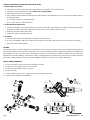
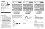
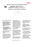
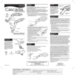
FEBCO Operation and Maintenance
805Y / 805YB / 805YS
Double Check Assembly (3/4" – 2")
®
FEATURES AND OPERATING PROCEDURES
This device consists of two independently operating poppet type check valves. Each check valve is spring loaded to maintain a minimum
of 1 PSIG differential pressure across the check in a no-flow condition. In a normal flow condition the checks open an amount corresponding to the flow rate. During a backflow (backpressure) situation the seat discs close and seal to prevent any flow reversal. Sizes 3/4"
through 2" (805Y, 805YB, 805YS, 805YR) include two spring-loaded, Y-pattern bronze check valves, two bronze shut-off valves and four
testcocks for field testing. All valves are threaded type and the unit is shipped completely assembled.
GENERAL SERVICE PROCEDURES (General service instructions applicable to all sizes.)
1. Rinse all parts with clean water prior to assembly.
2. DO NOT USE ANY PIPE DOPE, OIL, GREASE OR SOLVENT ON ANY PARTS unless instructed to do so.
4. Do not force parts. Parts should fit freely together. Excess force may cause damage and render the device inoperable.
5. Carefully inspect seals, seating surfaces, etc. for damage or debris.
5. Test unit after servicing to insure proper operations.
6. Refer to applicable parts list and figures for more information.
7. A table on page 3 provides size and material information for standard parts (non-special design). These parts can usually be
purchased locally from parts distributors.
8. Some water conditions can cause a buildup of calcium or similar material deposits on some moving parts. Normally this condition
would not occur on devices used in systems with varying flow rates. The scraping action of moving parts helps to remove any deposits.
However, with devices used on static systems such as firelines, any deposits would not be scraped away and could interfere with the
check valve operation. Devices in these applications should be disassembled and inspected on a periodic basis depending on water
quality. Any deposits should be removed from the center guiding stem and bushings. Use care to avoid damage to guiding surfaces.
TROUBLESHOOTING GUIDE
Symptom #1
Cause:
Solution:
Check fails to hold 1.0 PSID min.
A. Debris on sealing surfaces
Disassemble and clean
B. Leaking shut-off valve
Disassemble and clean or repair
C. Damaged seat disc or seat ring
Disassemble and replace
D. Damaged guide holding check open
Disassemble and replace guide pin
and/or sleeve bushing
E. Weak or broken spring
Disassemble and replace spring
Symptom #2
Cause:
Solution:
Chatter during flow conditions.
A. Worn or damaged guide
Disassemble and repair or replace guide
Symptom #3
Cause:
Solution:
Low flows passing through the
mainline valve.
A. Mainline check fouled
Inspect and clean, or repair
SERVICE PROCEDURES FOR MODELS 805Y, 805YB, 805YS
1. Disassembly-Check Valves
a. Close inlet and outlet shut-off valves. Bleed residual pressure by opening #2, #3 and #4 testcocks.
b. Unscrew cap using appropriate size wrench. NOTE: Cap is spring loaded.
c. Remove the spring and check assembly.
d. If any calcium or similar material has built-up on the inside surfaces of the guidehole in the cap, it can be removed with careful use
of a standard reamer.
(1) 3/4" through 1" devices: .6250 (5/8) Reamer
(2) 11/2" and 2" devices: .8750 (7/8) Reamer
2. Check Valve Seal Replacement
a. Hold check assembly in one hand and remove screw, washer, and seat disc. CAUTION: The use of pliers or other tools may damage
the parts and require unnecessary replacement. Do not scratch or mark sealing or guiding surfaces.
b. Install new disc after cleaning disc holder.
c. Position disc washer and retain with screw.
3. Assembly
a. Use reverse procedure for assembly with the following special instruction.
b. To ease cap installation, apply a thin coating of O-ring lubricant or any FDA approved grease to the O-ring prior to assembly.
c. Test unit to insure proper operation.
TESTING
All mechanical devices should be inspected on a regular basis to ensure they are working correctly. The assembly should be tested at
time of initial installation, after servicing or maintenance, and at least annually thereafter. Acceptable test procedures are published by
the Foundation for Cross Connection Control and Hydraulic Research at the University of Southern California (USC), The American
Water Works Association (AWWA), The American Society of Sanitary Engineering (ASSE Series 5000) and the Canadian Standards
Association (CAN/CSA B64•10). Please consult the regulatory authority in your area for more specific information.
HOW TO ORDER REPAIR KITS
1. Locate item number and kit number in this maintenance manual.
2. Verify the size of the valve the parts are to be used for.
3. Provide full model number located on I.D. plate.
4. Record kit number.
5. A serial number (located on the I.D. plate) will assist in ordering the proper kits.
6. Contact your local FEBCO Parts Distributor.
36
7
#1
Testcock
8
A
35
First
Check
Detail "A"
3/4" & 1"
Model 805YR
13
9
10
11
Second
Check
30
12
#2
#3
Testcock Testcock
29A
Inlet
Shutoff
30
#4
Testcock
Outlet
Shutoff
1
29
Page 2
FEBCO Model 805Y (3/4" - 2")
MODEL 805Y PARTS / REPAIR KITS
Model 805Y
/4"
1"
11/2"
2"
-
-
-
-
-
Cap
2
101-134
101-134
101-135
101-135
8
O-ring
2
398-226-72
398-226-72
398-235-72
398-235-72
9
Disc Holder
2
500-270
500-270
500-278
500-278
10
Seat Disc
2
400-099
400-099
400-103
400-103
11
Washer
2
300-084
300-084
300-108
300-108
Fig No.
Description
Qty.
1
Body
7
3
12
Screw
2
516-543-03
516-543-03
516-543-03
516-543-03
13
Spring
2
630-115
630-115
630-118
630-118
29
Ball Valve - Inlet
2
781-053
781-054
781-056
781-057
29A
Ball Valve - Outlet
2
781-048
781-049
781-051
781-052
30
Testcock
4
781-074
781-074
781-075
781-075
Model 805Y and 805YB Assemblies / Kits
Rubber Parts (Items: 8, 10 (2)each)
905-042
905-042
905-053
905-053
Check Assembly (Items: 8, 9, 10, 11, 12)
905-044
905-044
905-055
905-055
1"
11/2"
2"
/4"
1"
11/2"
2"
400-099s
400-099s
400-103s
400-103s
Model 805YB
Model 805YB utilizes the same components as the 805Y with the exception of the following:
Fig No.
Description
Qty.
13
Spring
2
3
/4"
630-167
Model 805YS
Model 805YS utilizes the same components as the 805Y with the exception of the following:
Fig No.
Description
Qty.
10
Seat Disc
2
3
805YS Assemblies / Kits
Rubber Parts (Items: 8, 10 (2)each)
905-042s
905-042s
905-053s
905-053s
Check Assembly (Items: 8, 9, 10, 11, 12)
905-044s
905-044s
905-055s
905-055s
/4"
1"
11/2"
2"
Model 805YR
Model 805YR utilizes the same components as the 805Y with the exception of the following:
3
Fig No.
Description
Qty.
35
Seat Ring
2
110-023
110-023
36
O-ring
2
398-028-72
398-028-72
Model 805Y Commerical Parts
Item
Description
Material
8
O-Ring
Nitrile
29
30
Ball Valve
Testcock
3
/4"
1"
11/2"
2"
568-226
568-226
568-235
568-235
2" x 21/4" x 1/8"
2" x 21/4" x 1/8"
31/8" x 33/8" x 1/8"
31/8" x 33/8" x 1/8"
11/2" NPT
Bronze
3
1" NPT
Brass
1
1
/4" NPT
/8" NPT
/8" NPT
1
/4" NPT
2" NPT
1
/4" NPT
These parts are commercially available through most hardware distributors or retailers. Shut-offs valves, testcocks, flange gaskets, etc. are also
commercially available but not listed.
FEBCO Model 805Y (3/4" - 2")
Page 3
FREEZE PROTECTION
The backflow prevention assembly may be subject to damage if the internal water is allowed to freeze. The unit must be protected from
freezing using a heated enclosure, insulation heat tape, or other suitable means. The unit must always be accessible for testing and
maintenance. If the system will be shut down during freezing weather, use the following procedures to drain internal passages.
Ball Valve Shut-Off Draining Procedure
If the assembly has been installed with ball valve shut-off valves, they must also be properly drained to
prevent freeze damage. After draining procedure has been completed on the backflow prevention assembly,
position all ball valve shut-offs and test cocks in a half open/half closed (45 degree) position.
Open the ball valve approximately 45 degrees while draining the pipeline and assembly to allow water
between the ball valve and valve body to drain. Leave the ball valve in this position for the winter to prevent
freeze damage.
The ball valve must be fully closed before the system is repressurized. OPEN AND CLOSE BALL VALVES
SLOWLY TO PREVENT DAMAGE TO THE SYSTEM CAUSED BY WATER HAMMER.
Main Valve Draining Procedure (3/4" - 2")
1. Close the main shut-off valve.
2. Open the inlet drain.
3. Open the inlet and outlet ball valves 45 degree (half open, half closed).
4. Open all testcocks.
5. Open the outlet drain.
6. Remove the cover and inlet check module until all water inside valve drains back out through inlet drain.
7. If you blowout the piping downstream of the backflow assembly using compressed air: Connect the air supply to the
outlet drain and close the outlet ball valve. After clearing the system with air, partially open the outlet ball valve. Leave all
drain valves, testcocks, and ball valves in half open/half closed position for the winter.
WARRANTY
All products manufactured and sold by CMB Industries, Inc. carry with them the following warranty: CMB Industries, Inc. warrants to the
original purchaser (who is the end user) all products manufactured by it will be free from defects in workmanship and material for a
period of one (1) year from the date of original shipment.
CMB Industries, Inc. also warrants that all internal components of 1/2" through 2" Model 850/860 and 1/2" through 1" Model 766 products,
will be free from defects in workmanship and material for a period of five (5) years from the date of original shipment and also that the
body only of the 1/2" through 11/4" Model 765 will be subject to a lifetime warranty against damage by freezing.
This warranty is applicable provided such products are used under normal conditions within the recognized pressure, flow and
temperature limits and are given normal service and care. CMB INDUSTRIES, INC. MAKES NO OTHER REPRESENTATION OR
WARRANTY OF ANY KIND, EXPRESSED OR IMPLIED, IN FACT OR IN LAW, AND EXPRESSLY DISCLAIMS ALL OTHER WARRANTIES, INCLUDING WITHOUT LIMITATION, THE WARRANTIES OF MERCHANTABILITY OR FITNESS FOR PARTICULAR PURPOSE.
In the event of a defect in material or workmanship of a product covered by this warranty, CMB Industries, Inc. shall, at its sole option,
repair or replace such defective product. CMB Industries, Inc. shall not be liable for any labor required to repair or replace any product
covered by this warranty. This warranty is void with respect to any such product which is altered or tampered with by anyone
without prior consent of CMB Industries, Inc. CMB Industries, Inc. shall not be liable under any circumstances for damages caused by
accident, misuse or abuse of the product or for failure to follow the installation, maintenance or operating instructions. IN NO EVENT
SHALL CMB INDUSTRIES BE LIABLE FOR CONSEQUENTIAL, INCIDENTAL, INDIRECT, PERSONAL INJURY, PROPERTY OR
PUNITIVE DAMAGES.
To make a claim under this warranty, the buyer must notify the factory in writing within ten (10) days of discovery of any claimed defects
or workmanship, and if authorized by the factory, shall return the product in the same condition as when received by the buyer,
transportation prepaid, to the factory or to such other location as directed by the factory. If said returned product is found by the factory
to be defective in workmanship or materials, it shall be repaired or replaced without charge, pursuant to the terms of this warranty. This
warranty excludes component parts or appurtenances not manufactured by CMB Industries, Inc. Any claims with respect to such
equipment must be made to the manufacturer thereof in accordance with the terms of the warranty, if any, given by such manufacturer,
or pursuant to such warranties as may exist by law. The physical or chemical properties of CMB Industries, Inc. products represent
typical, average values obtained in accordance with test methods and are subject to normal manufacturing variations. This information
is supplied as a technical service and is subject to change without notice.
Post Office Box 8070 • Fresno, California • U.S.A.
Tel# (559) 252-0791 • Fax# (559) 453-9030
www.FEBCOonline.com
Copyright 2001 CMB Industries, Inc.
PN 980116
MM805SM 11/01