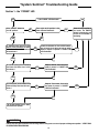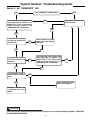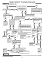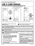
1
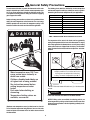
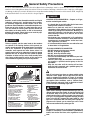
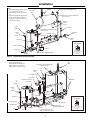
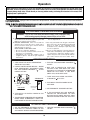
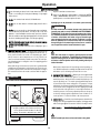
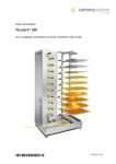
Commercial Induced Draft Water Heater
USE & CARE MANUAL
WITH INSTALLATION INSTRUCTIONS FOR THE CONTRACTOR
MULTI-FLUE COMMERCIAL MODELS
DESIGN
CER
TIFIED
®
CERTIFIED
R
!
!
Recognize this symbol as an Indication of Important
Safety Information!
!
NOTICE: This water heater is designed for use in a commercial application and the installation and maintenance of it should be performed by a qualified, licensed service personnel. If the foregoing assumption is not appropriate, then we recommend that you obtain
and retain our Residential Use & Care Manual which contains additional consumer warnings and information.
!
CALIFORNIA PROPOSITION 65 WARNING: This product contains chemicals known to the State of California to cause cancer, birth
defects or other reproductive harm.
!
WARNING: If the information in these instructions are not followed exactly, a fire or explosion may result
causing property damage, personal injury or death.
! FOR YOUR SAFETY!
— Do not store or use gasoline or other flammable
vapors or liquids or other combustible materials in
the vicinity of this or any other appliance. To do so
may result in an explosion or fire.
— WHAT TO DO IF YOU SMELL GAS
• Do not try to light any appliance.
• Do not touch any electrical switch; do not use any
phone in your building.
Printed in USA
Do Not Destroy this Manual. Please read carefully and
keep in a safe place for Future Reference.
• Immediately call your gas supplier from a neighbor's phone. Follow the gas supplier's instructions.
• If you cannot reach your gas supplier, call the fire
department.
• Do not return to your building until authorized by
the gas supplier or fire department.
— Improper installation, adjustment, alteration, service
or maintenance can cause injury, property damage
or death. Refer to this manual. Installation and service must be performed by a qualified installer, service agency or the gas supplier.
AP13968 (06/06)
TABLE OF CONTENTS
Safety Information
Safety Precautions . . . . . . . . . . . . . . . . 3-4, 12
Introduction
Local Installation Regulations . . . . . . . . . . . . 5
Location. . . . . . . . . . . . . . . . . . . . . . . . . . . . . . 5
READ THE SAFETY INFORMATION
Your safety and the safety of others are very important. There are many important safety messages in
this manual and on your appliance. Always read
and obey all safety messages.
!
This is the safety alert symbol. Recognize this symbol as
an indication of Important Safety Information! This sym bol alerts you to potential hazards that can kill or hurt you
and others.
All safety messages will follow the safety alert symbol and either the word “DANGER”, “WARNING”,
“CAUTION” or “NOTICE”.
Installation
Inspect Shipment . . . . . . . . . . . . . . . . . . . . . . 6
Water Connections . . . . . . . . . . . . . . . . . . . . 6
Gas Supply . . . . . . . . . . . . . . . . . . . . . . . . . . . 6
Typical Installation . . . . . . . . . . . . . . . . . . . . . 7
Venting. . . . . . . . . . . . . . . . . . . . . . . . . . . . . . . 8
These words mean:
! DANGER
An imminently hazardous
situation that will result in
death or serious injury.
! WARNING
A potentially hazardous
situation that could result
in death or serious injury
and/or damage to property.
! CAUTION
A potentially hazardous
situation that may result in
minor or moderate injury.
Wiring. . . . . . . . . . . . . . . . . . . . . . . . . . . . . . . . 8
Installation Checklist . . . . . . . . . . . . . . . . . . . . 9
Operation
Lighting Procedure . . . . . . . . . . . . . . . 10 & 11
Temperature Settings . . . . . . . . . . . . . . . . . . 12
Emergency Cut Off . . . . . . . . . . . . . . . . . . . . 14
Maintenance
Routine Preventive Maintenance . . . . . . . . .14
Burners . . . . . . . . . . . . . . . . . . . . . . . . . . . . . 13
Venting System . . . . . . . . . . . . . . . . . . . . . . . 13
Anode Inspection . . . . . . . . . . . . . . . . . . . . . 14
Seasonal Operation . . . . . . . . . . . . . . . . . . . 14
Tank. . . . . . . . . . . . . . . . . . . . . . . . . . . . . . . . 14
Troubleshooting
System Sentinel Diagnosis . . . . . . . . . 15 - 20
Customer Service
Parts List . . . . . . . . . . . . . . . . . . . . . . . . . . . . 21
How to Obtain Service Assistance. . . . . . . . 24
Notice:
Attention is called to observe
a specified procedure or
maintain a specific condition.
! General Safety Precautions
To meet commercial water use needs, the thermostat on this water
heater is adjustable up to 180°F. However, water temperatures over
125°F. can cause severe burns instantly or death from scalds. This
is the preferred starting point for setting the control for supplying
general purpose hot water.
The following chart details the relationship of water temperature
and time with regard to scald injury and may be used as a guide in
determining the safest water temperature for your applications.
Temperature
120° F
125° F
130° F
135° F
140° F
145° F
150° F
155° F
Safety and energy conservation are factors to be considered when
setting the water temperature on the thermostat. The most energy
efficient operation will result when the temperature setting is the
lowest that satisfies the needs consistent with the application.
!
DANGER
Time to Produce Serious Burn
More than 5 minutes
1 1 / 2 to 2 minutes
About 30 seconds
About 10 seconds
Less than 5 seconds
Less than 3 seconds
About 1 1 / 2 seconds
About 1 second
Table courtesy of Shriners Burn Institute
TIME / TEMPERATURE RELATIONSHIPS IN SCALDS
The temperature of the water in the heater can be regulated by
setting the temperature dial on front of the thermostat. To comply
with safety regulations the thermostat was set at its lowest setting
before water heater was shipped from the factory. The illustration
below illustrates the thermostat and how to adjust the water temperature.
HOT
120
50
100
0
11 40
14
0
160
70
0
120
14
0
6
130
0
°F
°C
BURN
18
0
8
To adjust the water temperature, insert a small
straight screwdriver into slotted screw in hole in
front of thermostat and turn wheel to desired
setting. Thermostat is adjustable up to 180º F.
Water temperature over 125°F can
cause severe burns instantly or
death from scalds.
CAUTION!! - Hotter water increases the risk of SCALDING!
Children, disabled and elderly are
at highest risk of being scalded.
See instruction manual before
setting temperature at water
heater.
Feel water before bathing or
showering.
Temperature limiting valves are
available, see manual.
Honeywell
White-Rodgers
THERMOSTAT
NOTICE: Each water heater will contain one (1) of the above thermostats.
! DANGER
Hotter water increases the Potential for Hot Water SCALDS.
NOTICE: Mixing valves are available for reducing point of use
water temperature by mixing and cold water in branch water lines
Contact a licensed plumber or the local plumbing authority for further information.
Maximum water temperatures occur just after burner has shut off.
To find hot water temperature being delivered, turn on a hot water
faucet and place a thermometer in the hot water stream and read
the thermometer.
3
! General Safety Precautions
Be sure to read and understand the entire Use & Care Manual before attempting to install or operate this water heater. Pay particular
attention to the following General Safety Precautions. Failure to follow these warnings could result in a fire or explosion, causing property damage, bodily injury or death . Should you have any problems understanding the instructions in this manual, STOP, and get help
from a qualified installer or service technician or the gas supplier.
! DANGER
LIQUEFIED PETROLEUM MODELS — Propane, or LP gas,
must be used with great caution.
Gasoline, as well as other flammable materials and liquids
(adhesives, solvents, etc.), and the vapors they produce,
are extremely dangerous. DO NOT handle, use or store
gasoline or other flammable or combustible materials anywhere near or in the vicinity of a water heater. Be sure to
read and follow the warning label pictured below and
other labels on the water heater, as well as the warnings
printed in this manual. Failure to do so can result in property damage, bodily injury, or death.
• It is heavier than air and will collect first in lower areas
making it hard to detect at nose level.
• Make sure to look and smell for LP leaks before
attempting to light appliance. Use a soapy solution to
check all gas fittings and connections. Bubbling at a
connection indicates a leak that must be corrected.
When smelling to detect an LP leak, be sure to sniff
near the floor too.
• Gas detectors are recommended in LP applications
and their installation should be in accordance with the
manufacturer's recommendations and/or local laws,
rules, regulations or customs.
• It is recommended that more than one method be used
to detect leaks in LP applications.
! DANGER
Failure to properly vent the water heater to the outdoors
as outlined in the Venting Section of this manual can
result in unsafe operation of the water heater. To avoid the
risk of fire, explosion, or asphyxiation from carbon
monoxide, never operate this water heater unless it is
properly vented and has an adequate air supply for proper
operation. Be sure to inspect the vent system for proper
installation at initial start-up; and at least annually thereafter. Refer to Maintenance section of this manual for
more information regarding vent system inspections.
!
FLAMMABLES
IF LP GAS IS PRESENT OR SUSPECTED:
• DO NOT attempt to find the cause yourself;
• DO NOT try to light any appliance;
• DO NOT touch any electrical switch;
• DO NOT use any phone in your building.
• Leave the house immediately and make sure your family and pets leave also.
• Leave the doors open for ventilation and contact the
gas supplier, a qualified service agency or the fire
department.
• Keep the area clear until the service call has been
made, the leak is corrected, and a qualified agency has
determined the area to be safe.
DANGER
Both LP and natural gas have an odorant added to help
detection. Some people may not physically be able to
smell or recognize this odorant. If unsure or unfamiliar
about the smell associated with LP or natural gas, ask the
gas supplier. Other conditions, such as "Odorant Fade",
which causes the odorant to "fade", or diminish in intensity can also hide or camouflage a gas leak.
Flammable Vapors
! Vapors from flammable
liquids will explode and
catch fire causing death or
severe burns.
Do not use or store flammable
products such as gasoline,
solvents or adhesives in the
same room or area near the
water heater.
Keep flammable products:
1. far away from heater,
2. in approved containers,
3. tightly closed and
4. out of children's reach.
Installation:
Do not install water heater
where flammable products will
be stored or used unless the
main burner and pilot flames
Water heater has a main
burner and pilot flame.
The pilot flame:
1. which can come on at
any time and
2. will ignite flammable
vapors.
Vapors:
1. cannot be seen,
2. are heavier than air,
3. go a long way on the
floor and
4. can be carried from
other rooms to the pilot
flame by air currents.
! DANGER
Water heaters utilizing Liquefied Petroleum gas (LP) are
different from natural gas models. A natural gas heater will
not function safely on LP gas and vice versa. No attempt
should ever be made to convert a heater from natural gas
to LP gas. To avoid possible equipment damage, personal
injury or fire: DO NOT connect this water heater to a fuel
type not in accordance with unit data plate. Propane for
propane units. Natural gas for natural gas units. These
units are not certified for any other type fuel.
are at least 18" above the
floor. This will reduce, but not
eliminate, the risk of vapors
being ignited by the main
burner or pilot flame.
Read and follow water heater warnings and instructions. If owners
manual is missing, contact the retailer or manufacturer.
4
LP appliances should not be installed below-grade (for
example, in a basement) if such installation is prohibited by
federal, state and/or local laws, rules, regulations or customs.
Introduction
D. RESTAURANTS — If the water heater is to be installed in a restaurant or other location where the floor is frequently cleaned, it must
be elevated to provide at least six inches (15 cm) of clearance
from the floor to comply with NSF International recommendations.
A factory-designed leg extension kit is available for this purpose
from the distributor or store where the water heater was purchased.
Read and Review this entire Manual with special emphasis on
Pages 6-9 prior to any installation work.
LOCAL INSTALLATION REGULATIONS
This water heater must be installed in accordance with these instructions, local codes, utility company requirements and/or, in the
absence of local codes, the latest edition of the National Fuel Gas
Code, ANSI Z223.1/NFPA 54 and/or CSA B149.1, Natural Gas and
Propane Installation Code.
E. C O M B U S T I O N & V E N T I L A T I O N A I R — Proper operation of the
water heater requires air for combustion and ventilation. If the
water heater is installed in a building of conventional frame, masonry or metal construction, and there are no other appliances
installed that require an air supply, infiltration air is normally adequate for proper combustion and ventilation, and an outside air
supply for the water heater may not be required. However, if the
water heater is installed in a confined space, or the building is of
unusually tight construction, then an outside air supply must be provided. Provisions for Combustion and Ventilation air must comply with the applicable codes and standards as defined in the Local
Installation Regulations section on page 5.
FOR INSTALLATIONS IN THE UNITED STATES:
LOCATION
A. The water heater should be installed in a clean, dry location as
close as practical to the gas vent terminals. Long hot water lines
should be insulated to conserve water and energy. The water
heater and water lines should be protected from exposure to freezing temperatures.
B. A gas fired water heater should not be installed in a space where
liquids which give off flammable vapors are to be used or stored.
Such liquids include gasoline, LP gas (butane and propane), paint
or adhesives and their thinners, solvents or removers. Because of
natural air movement in a room or other enclosed space, flammable
vapors can be carried some distance from where their liquids are
being used or stored. The open flame of the water heater’s intermittent pilot or main burner can ignite these vapors causing an
explosion or fire which may result in severe burns or death to those
in range, as well as property damage. For these reasons, installation of a gas fired water heater in a garage is not desirable.
If the water heater is to be installed in a confined space, defined
as one having a volume of less that 50 cubic feet (1.4 cu. meters)
per 1000 Btu/h of the total input of all appliances within that space,
an air supply must be provided. The air must be supplied through
two permanent openings of equal area, one of which is to be located
approximately 12 inches (30cm) above the floor and the other of
which is to be located approximately 12 inches (30cm) below the
ceiling. The minimum net free area of each opening must be not
less than one square inch per 1000 Btu/h of the total input of all the
appliances in the enclosure or structure, if each of the openings
communicates with other unconfined areas inside the structure.
If a location in a garage is the only alternative, the gas water heater
should be installed so that the open flame of the pilot and main
burner are no less than 18 inches above the garage floor. The
water heater must be located or protected so it is not subject to
physical damage by moving vehicles or area flooding. Raising the
gas fired water heater will reduce BUT NOT eliminate the possibility of lighting the vapor of any flammable liquids which may be
improperly stored or accidentally spilled.
If the required air is to be supplied directly from outdoors (or a
freely ventilated attic or crawl space), or through vertical ducts,
there must be two openings located as specified above, and each
must have a minimum net free area of not less than one square
inch (6.5 sq. cm) per 4,000 Btu/h of the total input rating of all appliances in the en-closure.
NOTE: If the openings are to be covered with a protective screen
or grill, the net free area of the covering material must be used in
determining the size of the openings mentioned above. Protec t i v e s c r e e n i n g f o r t h e o p e n i n g s M U S T N O T b e s m a l l e r t h a n 1/4 inch
(.64 cm) mesh to resist clogging by lint or other debris.
C. All models are certified for installation on combustible floors and
in alcoves. The minimum side and top clearance to walls and ceiling for providing protection of combustible materials are shown
on the water heater’s rating label. A front clearance of 18 inches
(46 cm) should be provided for adequate inspection and servicing.
If the water heater must be installed on carpeting, place a metal
or wood panel beneath water heater extending beyond its full
width and depth at least 3 inches (7.6 cm) in all directions. If the
water heater is installed in an alcove, the entire floor must be covered by the panel.
For additional information regarding combustion and ventilation
air supply requirements, refer to the latest edition of the American National Standard / National Fuel Gas Code, ANSI Z223.1
FOR INSTALLATIONS IN CANADA:
While the requirements for U.S. installations outlined above are
generally true in Canada, precise requirements for combustion
and ventilation air supplies are detailed in the CAN/CGA B149 Installation Codes; under “Venting Systems and Air Supply for Appliances”. To ensure that the water heater is properly installed,
those requirements must be followed.
Large exhaust fans can lower the air pressure inside a building
or room and interfere with proper venting and operation. Commercial kitchens or other locations that must maintain a high flow
of exhaust air should have the water heater installed in a separate room with combustion and ventilation air supplied directly
from outside as described above.
F . C O R R O S I V E A T M O S P H E R E S — The heater should not be installed near an air supply containing halogenated hydrocarbons. For example, the air in beauty shops, dry cleaning establishments, photo processing labs, and storage areas for
liquid and powdered bleaches or swim pool chemicals often
! CAUTION
The water heater should not be located in an area where leakage
of the tank or connections will result in damage to the area adjacent to it or to lower floors of the structure. When such areas cannot be avoided, it is recommended that a suitable catch pan, adequately drained, be installed under the water heater. The pan
MUST NOT restrict the flow of combustion air flow to bottom of
water heater.
NOTICE: Auxiliary catch pan installation MUST conform to the
applicable local codes.
5
Installation
3. W A T E R C O N N E C T I O N S — This water heater may be connected
individually, in multiples with others, or with an external hot water
storage tank.
contain such hydrocarbons. The air there may be safe to
breathe, but when it passes through a gas flame, corrosive
elements are released that will shorten the life of any gas burning appliance. Propellants from common spray cans or gas
leaks from refrigeration equipment are highly corrosive after
passing through a flame. The limited warranty is voided when
failure of water heater is due to a corrosive atmosphere. (Reference is made to the limited warranty for complete terms and
conditions.)
Inlet water connections are made to the lower coupling on the heater,
and outlet water connections are made to the upper coupling or, if
desired on models so equipped, the optional top connections may
be utilized.
Each water heater is supplied with the necessary diffuser tubes,
to make the water connections that will ensure proper performance.
If special instructions are required for any specific water heater,
they will be included with the diffuser tube.
The manufacturer’s warranty does not cover any damage or
defect caused by installation, or attachment, or use of any special
attachment such as energy saving devices (other than those
authorized by the manufacturer) into, onto, or in conjunction with
the water heater. The use of such unauthorized devices may
shorten the life of the water heater and may endanger life and
property. The manufacturer disclaims any responsibility for such
loss or injury resulting from the use of such unauthorized devices.
Cap or plug unused connections. Use only clean, new galvanized
steel, copper or approved plastic pipe for water connections. Local
codes or regulations shall govern the exact type of material to be
used. The installation of unions on the inlet and outlet water lines
and a shut-off valve in at least the cold water inlet line is recommended, so the water heater may be easily disconnected for servicing. Dielectric unions are not required for protection of water
heater.
When this water heater is supplying general purpose hot water
requirements for use by individuals, a thermostatically controlled
mixing valve is recommended to reduce the risk of scald injury.
Contact a licensed plumber or the local plumbing authority for further information.
Thermometer(s) should be installed so that they indicate the temperature of the water at or near the outlet of the water heater and
storage tank(s) if provided. See Fig. 4 on page 7.
1. INSPECT SHIPMENT — for possible damage. The manufacturer’s
responsibility ceases upon delivery of goods to the carrier in good
condition. Any claims for damage, shortage in shipments, or non
delivery must be filed immediately against carrier by consignee.
2. T H E R M A L E X P A N S I O N — D e t e r m i n e i f a c h e c k v a l v e e x i s t s i n
t h e i n l e t w a t e r l i n e . It may have been installed in the cold water
line as a separate back flow preventer, or it may be part of a
pressure reducing valve, water meter or water softener. A check
valve located in the cold water inlet line can cause what is referred to as a ” c l o s e d w a t e r s y s t e m ” . A cold water inlet line with
no check valve or back flow prevention device is referred to as
an ”open” water system.
4. R E L I E F V A L V E — A new factory installed combination pressure
and temperature relief valve, complying with the Standard for Relief Valves and Automatic Gas Shutoff Devices for Hot Water Supply Systems, ANSI Z21.22, or Standard CAN1-4.4, Temperature,
Pressure, Temperature and Pressure Relief Valves and Vacuum
Relief Valves is provided with the water heater. No valve is to be
placed between the relief valve and the water heater. For a circulating tank installation, the separate storage tank(s) must have
similar protection. The pressure rating of the relief valve must not
exceed 150 psi (160 psi for ASME models), the maximum working
pressure as marked on front of the water heater.
The Btu/h rating of the relief valve must equal or exceed the Btu/h
input of the water heater as marked on its rating plate.
Connect the outlet of the relief valve to a suitable open drain. The
discharge line must pitch downward from the valve to allow complete draining (by gravity) of the relief valve and discharge line, and
be no smaller than the outlet of the valve. The end of the discharge
line should not be threaded or concealed and should be protected from freezing. No valve of any type, restriction or reducer coupling should be installed in the discharge line. Local codes shall
govern the installation of relief valves.
As water is heated, it expands in volume and creates an increase
in the pressure within the water system. This action is referred
to as ” t h e r m a l e x p a n s i o n ” . In an ”open” water system, expanding water which exceeds the capacity of the water heater flows
back into the city main where the pressure is easily dissipated.
A ” c l o s e d w a t e r s y s t e m ” , however, prevents the expanding water
from flowing back into the main supply line, and the result of
” t h e r m a l e x p a n s i o n ” can create a rapid, and dangerous pressure increase in the water heater and system piping. This rapid
pressure increase can quickly reach the safety setting of the relief valve, causing it to operate during each heating cycle. Thermal expansion, and the resulting rapid, and repeated expansion
and contraction of components in the water heater and piping
system can cause premature failure of the relief valve, and possibly the heater itself.Replacing the relief valve w i l l n o t correct
the problem!
The suggested method of controlling thermal expansion is to install
an expansion tank in the cold water line between the water heater
and the check valve. The expansion tank is designed with an air cushion built in that compresses as the system pressure increases,
thereby relieving the over pressure condition and eliminating the repeated operation of the relief valve. Other methods of controlling thermal expansion are also available. Contact your installing contractor,
water supplier, or plumbing inspector for additional information regarding this subject.
5. G A S S U P P L Y — The inlet gas pressure to the water heater must
not exceed 10.5” w.c. (2.6 kPa) for Natural gas. For purposes of
input adjustment, the minimum inlet gas pressure (with main burner on) is shown on the rating plate. Check to see if high or low gas
pressure is present and then contact the gas company for correction.
The gas line should be of adequate size to prevent undue pressure
drop. Sizing based upon Table 1 (on pg. 9) is recommended. No
additional allowance is necessary for an ordinary number of fittings.
If a recirculation line is installed, the return connection should be
made to a tee close to the inlet connection on the water heater.
A check valve should always be installed in the recirculation line
to prevent cold water from entering.
6
Installation
NOTES:
1.) Heater's Outlet Piping must have upward
slope, otherwise use Circulator
2.) If Vertical Tank is used, follow same layout.
3.) The gas supply piping must be adequately supported and aligned to minimize
loads (forces) on the water heater’s gas
valve and burner system.
Discharge Pipe to Suitable Open Drain
Hot Outlet
Storage
Tank
Temperature & Pressure Relief Valve
(See Local Code)
2"
Optional
Return
Outlet
To Gas
Supply
Check Valve
Temperature & Pressure Relief Valve
(See Local Code)
Manual
Gas
Shut-Off
Cold Water
Inlet
Recirculation Loop
Check Valve
Shut-Off
Valve
Thermostat
Vacuum Relief Valve
(Not Supplied)
SYSTEM SENTINE
L
POWER
THERMOSTAT
IGNITION
Ground Joint Union
PILOTVALVE
ECO
MAINVALVE
®
Air Gap 6"
Sediment Trap
If required, install per local codes
and valve manufacturer’s
instructions.
Cap
Discharge Pipe to Suitable Open Drain
Gas Valve
Figure 4. — Typical Gravity Circulating System
NOTES:
1.) The gas supply piping must be
adequately supported and aligned to
minimize loads (forces) on the water
heater’s gas valve and burner system.
Hot
Outlet
Temperature & Pressure Relief Valve
(See Local Code)
Shut-Off
Valve
Cold
Inlet
Recirculation Loop
Recirculator
To
Gas
Supply
Temperature & Pressure
Relief Valve
Manifolds
Manual
Gas
Shut-Off
Circulator
Control
(Optional)
Check Valve
Thermostat
Vacuum Relief Valve
(Not Supplied)
SYSTEM SENTINEL
POWER
THERMOSTAT
IGNITION
Ground Joint Union
PILOT VALVE
ECO
MAIN VALVE
®
Check Valve
Sediment Trap
Air Gap 6"
Cap
Gas Valve
Circulator*
* Circulator may be wired to run
continuously without the Control
Discharge Line
to Suitable Open Drain
Figure 5. — Typical Forced Circulation Tank System with Factory Supplied Jacketed & Insulated Storage Tanks.
7
If required, install per local codes
and valve manufacturer’s
instructions.
Installation
7. VENTING — The responsibility for providing a vent of adequate capacity and in good usable condition is that of the installing contractor. There is a limit to the Btu/h capacity of any given vent or chimney style and height. For installations in the United States, capacity tables are printed in Appendix “G” of the National Fuel Gas Code
(ANSI Z223.1). For installations in Canada, this information is contained in Appendix B of CAN/CGA B-149 Installation Codes
As an alternate method for sizing a vent connected to more than one
appliance, the effective area of the vent shall be not less than the
area of the largest vent connector plus 50% of the areas of additional draft hood outlets.
Any horizontal run of vent connector connecting the to the gas vent
or chimney, must have an upward slope of at least 1/4” per foot of
length. Single wall vent connectors must be at least 6” from adjacent unprotected combustible surfaces. Joints of vent connectors
should be securely fastened by sheet metal screws or other approved method. Provide support for vent, or vent connectors to keep
weight off of the water heater.
8. W I R I N G — A polarized 120V 50/60 Hz power supply, with suitable disconnect means, must be connected to the black and white
leads provided. The current draw by the Induced Draft unit is 2.5
amps. The water heater, when installed, must be electrically
grounded in accordance with local codes, or, in the absence of
local codes, with the National Electrical Code, ANSI/NFPA 70 in
the United States; or CSA C22.1 Electrical Code, in Canada. Refer
to Fig. 14 on page 22 & 23 of this manual for water heater internal
wiring diagrams.
A ground joint union and manual shutoff valve should be installed
in the gas line near the water heater so that the burner assembly
may be easily removed. The shut-off valve must be readily accessible for turning on or off. See Fig. 4 on page 7.
A sediment trap must be installed at the bottom of the gas line.
See Fig. 4 on page 7.
6. LEAK TESTING — The water heater and its gas connections MUST
be leak tested at normal operating pressure before it is placed in
operation. Turn ON the manual gas shut-off valve near the water
heater. Use a soapy water solution to test for gas leaks at all connections and fittings. Bubbles indicate a gas leak that must be
corrected. The water heater factory connections to the gas valve
should also be leak tested after placing the water heater in operation.
NEVER use open flame to test for gas leaks, as bodily injury or
property damage could result.
P R E S S U R E T E S T I N G T H E G A S S U P P L Y S Y S T E M — The water
heater and its manual gas shut-off valve MUST be disconnected
from the gas supply piping system during any high pressure
testing of that system at pressures in excess of 1/2 psi
(14” w.c. / 3.5 kPa).
The water heater MUST be isolated from the gas piping system
by closing the manual gas shut-off valve during any pressure testing of the gas supply piping at pressures equal to or less than
1/2 psi (14” w.c. / 3.5 kPa).
N O T I C E : D O NOT u s e i n c o n j u n c t i o n w i t h a G F C I .
NOTICE: This water heater uses Category 1, Type B Appliance. Dou ble wall venting is preferred.
8
Installation
❑ Soap and water solution used to check all connections and
A. W a t e r H e a t e r L o c a t i o n
fittings for possible gas leak.
❑ Close to area of vent.
❑ Gas Company inspected installation (if required).
❑ Indoors and protected from freezing temperatures.
❑ Ample sizes of supply pipe.
❑ Proper clearance from combustible surfaces observed and
❑ Gas pressure check based on fuel type.
water heater not installed on carpeted floor.
❑ Air supply free of corrosive elements and flammable vapors.
D. R e l i e f V a l v e
❑ Provisions made to protect area from water damage.
❑ Discharge line run to open drain.
❑ Sufficient room to service heater.
❑ Discharge line protected from freezing.
B. W a t e r S u p p l y
E. V e n t i n g
❑ Water heater completely filled with water.
❑ All pipe connections are secure (at inducer, vent terminals
and for each pipe joint connection)
❑ Water heater and piping air vented.
❑ Vent terminal mounted properly.
❑ Water connections tight and free of leaks.
F. C o m b u s t i o n A i r
❑ Thermal expansion tank (if required).
❑ Adequate combustion air.
C. G a s S u p p l y
❑ Alternate fresh air source (if required).
❑ Gas line equipped with shut-off valve, union, and sediment
❑ Negative air pressure potential.
trap/drip leg.
❑ Approved pipe joint compound used.
TABLE 1
Maximum Capacity of Pipe in Cubic Feet of Gas per Hour for Gas Pressures of
0.5 psig or Less and a Pressure Drop of 0.3 Inch Water Column
Based on a 0.60 Specific Gravity Natural Gas; If 1.5 Specific Gravity L.P. Gas is used, multiply capacity by 0.63
Nominal
Iron Pipe Size,
Inches
1/2
3/4
1
1 1/4
1 1/2
2
2 1/2
3
4
Internal
Diameter
Inches
.622
.824
1.049
1.380
1.610
2.067
2.469
3.068
4.026
Length of Pipe, Feet
10
20
132
92
278
190
520
350
1,050
730
1,600
1,100
3,050
2,100
4,800
3,300
8,500
5,900
17,500 12,000
30
40
50
60
70
73
152
285
590
890
1,650
2,700
4,700
9,700
63
130
245
500
760
1,450
2,300
4,100
8,300
56
115
215
440
670
1,270
2,000
3,600
7,400
50
105
195
400
610
1,150
1,850
3,250
6,800
46
96
180
370
560
1,050
1,700
3,000
6,200
9
80
43
90
170
350
530
990
1,600
2,800
5,800
90
100
125
150
175
200
40
84
160
320
490
930
1,500
2,600
5,400
38
79
150
305
460
870
1,400
2,500
5,100
34
72
130
275
410
780
1,250
2,200
4,500
31
64
120
250
380
710
1,130
2,000
4,100
28
59
110
225
350
650
1,050
1,850
3,800
26
55
100
210
320
610
980
1,700
3,500
Operation
Before operating this water heater, be sure to read and follow the instructions on the label pictured below and all other labels on the
water heater, as well as the warnings printed in this manual. Failure to do so can result in unsafe operation of the water heater resulting
in property damage, bodily injury, or death. Should you have any problems reading or following the instructions in this manual, STOP,
and get help from a qualified person.
Lighting Instructions for the GD100 - 250, GD100 - 270, and GD100 - 310 Units Only.
1. LIGHTING PROCEDURE - Lighting procedures are outlined on the label pictured below. This label is also located on the water heater near the thermostat.
NOTICE: The Gas Valve supplied with this water heater may vary from the one pictured on the label below, but the Lighting Instructions are the same for all
types of valves supplied with this model water heater.
FOR YOUR SAFETY READ BEFORE OPERATING
WARNING: If you do not follow these instructions exactly, a fire or explosion may
result causing property damage, personal injury or loss of life
A. This appliance is equipped with an ignition
device which automatically lights the pilot. DO
NOT try to light the pilot by hand.
B. BEFORE OPERATING smell all around the
appliance area for gas. Be sure to smell next to
the floor because some gas is heavier than air
and will settle on the floor.
WHAT TO DO IF YOU SMELL GAS
• Do not try to light any appliance
• Do not touch any electrical switch; do not use
any phone in your building.
• Immediately call your gas supplier from a
neighbor's phone. Follow the gas supplier's
instructions.
• If you cannot reach your gas supplier, call
the fire department.
C. Use only your hand to turn the gas control knob.
Never use tools. If the knob will not turn by hand,
don't try to repair it, call a qualified service
technician. Force or attempt to repair may result
in a fire or explosion.
D. Do not use this appliance if any part has been
under water. Immediately call a qualified service technician to inspect the appliance and to
replace any part of the control system and any
gas control which has been under water.
OPERATING INSTRUCTIONS
1. STOP! READ THE SAFETY INFORMATION
ABOVE ON THIS LABEL.
5. TURN THE "GAS COCK KNOB" CLOCKWISE
TO "OFF."
2. USING A SLOTTED SCREW DRIVER — INSERT
INTO TEMPERATURE ADJUSTMENT OPENING. TURN SCREW CLOCKWISE
TO THE
LOWEST SETTING
6. WAIT FIVE (5) MINUTES TO CLEAR OUT
ANY GAS. IF YOU THEN SMELL GAS, STOP!
FOLLOW "B" IN THE SAFETY INFORMATION
ABOVE ON THIS LABEL. IF YOU DON'T
SMELL GAS, GO TO NEXT STEP.
7. T U R N " G A S C O C K K N O B " C O U N T E R CLOCKWISE
TO " O N " .
THERMOSTAT
ON
8. TURN ON ALL ELECTRIC POWER TO THE
APPLIANCE.
OFF
GAS COCK
KNOB
GAS VALVE
INDEX
TEMPERATURE
ADJUSTMENT
SCREW
3. TURN OFF ALL ELECTRIC POWER TO THE
APPLIANCE.
4. THIS APPLIANCE IS EQUIPPED WITH AN IGNITION
DEVICE WHICH AUTOMATICALLY LIGHTS THE
PILOT. DO NOT TRY TO LIGHT THE PILOT BY HAND.
9. SET THERMOSTAT TO DESIRED SETTING
10. IF THE APPLIANCE WILL NOT OPERATE,
FOLLOW THE INSTRUCTIONS "TO TURN
OFF GAS TO APPLAINCE" AND CALL YOUR
SERVICE TECHNICIAN OR GAS SUPPLIER.
TO TURN OFF GAS TOAPPLIANCE
1. SET THE THERMOSTAT TO LOWEST SETTING.
2. TURN OFF ALL ELECTRIC POWER TO THE
APPLIANCE IF SERVICE IS TO BE PERFORMED.
1. TURN THE "GAS COCK KNOB" CLOCKWISE
TO "OFF".
10
Operation
Before operating this water heater, be sure to read and follow the instructions on the label pictured below and all other labels on the
water heater, as well as the warnings printed in this manual. Failure to do so can result in unsafe operation of the water heater resulting
in property damage, bodily injury, or death. Should you have any problems reading or following the instructions in this manual, STOP,
and get help from a qualified person.
Lighting Instructions for the GD100 - 360 Unit Only.
1. LIGHTING PROCEDURE - Lighting procedures are outlined on the label pictured below. This label is also located on the water heater near the thermostat.
NOTICE: The Gas Valve supplied with this water heater may vary from the one pictured on the label below, but the Lighting Instructions are the same for all
types of valves supplied with this model water heater.
FOR YOUR SAFETY READ BEFORE OPERATING
WARNING: If you do not follow these instructions exactly, a fire or explosion
may result causing property damage, personal injury or loss of life.
A. This appliance is equipped with an ignition
• If you cannot reach your gas supplier, call
device which automatically lights the pilot. DO
the fire department.
NOT try to light the pilot by hand.
B. BEFORE OPERATING smell all around the
C. Use only your hand to turn thegas control knob.
appliance area for gas. Be sure to smell next to
Never use tools. If the knob will not turn by hand,
the floor because some gas is heavier than air
don't try to repair it, call a qualified service
and will settle on the floor.
technician. Force or attempted repair may result
WHAT TO DO IF YOU SMELL GAS
in a fire or explosion.
• Do not try to light any appliance
• Do not touch any electric switch; do not use D. Do not use this appliance if any part has been
under water. Immediately call a qualified ser any phone in your building.
vice technician to inspect the appliance and to
• Immediately call your gas supplier from a
replace any part of the control system and any
neighbor's phone. Follow the gas supplier's
gas control which has been under water.
instructions.
OPERATING INSTRUCTIONS
1. STOP! READ THE S AFETY INFORMATION 5. TURN THE "GAS CONTROL KNOB" CLOCKABOVE ON THIS LABEL.
WISE
TO " OFF".
2. REMOVE OUTER COVER. U SING A SLOTTED 6. WAIT FIVE (5 ) MINUTES TO CLEAR OUT ANY
SCR EWDRIVE R - I NSERT INTO SLOT IN CENTER
GAS. IF YOU THEN SMELL GAS, STO P! FOL OF DIAL. T URN DIAL COUNTERCLOCKWISE
LOW "B" IN THE S AFETY INFORMATION
TO THE LOWEST SET TING. THERMOSTAT
ABOVE ON THIS LABEL. IF YO U DON'T SMEL L
Gas Co ntrol
Ind ex
GAS, GO TO NEXT STEP.
Kno b
GAS VALVE
TEMPERATURE
ADJUSTMENT
DIAL
7. TURN THE "GAS CONTROL K NOB" COUNTERCLOCKWISE
T O "ON".
NOTE: Thermostat
shown with cover
removed.
8. TURN ON ALL ELECTRIC POWER T O THE
APPLIANCE.
9. S ET THERMOSTAT TO DESIR ED SETTING.
I NSTALL OUTER COVER.
10. IF THE APPLIANCE WILL NOT OPERATE, FOLLOW THE INSTRUCTIONS "TO TURN OFF GAS
TO APPLIANCE" AND CALL YOUR SERVICE
TECHNICIAN OR GAS SUPPLIER.
3. TURN OFF ALL E LECTRIC POWER T O THE
APPLIANCE.
4. THIS APPLIANCE IS EQUIPPE D WITH AN
IGNITION DEVICE WHICH AUTOMATICALLY
LIGHTS T HE PILOT. DO NOT TRY TO LIGHT THE
PILOT BY HAND.
TO TURN OFF GAS TO APPLIANCE
1. SET THE THERMOSTA T TO LOWEST SETTING. 3. TURN THE "GAS CONTROL KNOB" CLOCK2. TURN O FF ALL EL ECTRIC PO WER TO T HE
WISE TO "OFF".
APPLIAN CE IF SERVI CE IS TO BE PERFORME D.
11
Operation
SAFETY PRECAUTIONS
A. Do turn off manual gas shut-off valve if water heater has been subjected to over heating, fire, flood, physical damage or if gas supply
fails to shut off.
mops to accumulate near water heater.
F. If there is any difficulty in understanding or following the OPERATION or MAINTENANCE instructions, it is recommended that a
qualified person or serviceman perform the work.
B. Do Not turn on water heater unless it is filled with water.
Hydrogen gas can be produced in a hot water system served by
C. Do Not turn on water heater if cold water supply shut-off valve is
closed.
! CAUTION
this water heater that has not been used for a long period of time
(generally two weeks or more). HYDROGEN GAS IS EXTREMELY
FLAMMABLE!! To dissipate such gas and to reduce risk of injury,
it is recommended that the hot water faucet be opened for several minutes at the kitchen sink before using any electrical appliance connected to the hot water system. If hydrogen is present,
there will probably be an unusual sound such as air escaping
through the pipe as the water begins to flow. Do not smoke or
use an open flame near the faucet at the time it is open.
D. Do Not store or use gasoline or other flammable vapors and liquids,
such as adhesives or paint thinner, in vicinity of this or any other
appliance. If such flammables must be used, open doors and windows for ventilation, and all gas burning appliances in vicinity should
be shut off, including their pilot lights, to avoid vapors igniting.
NOTICE: Flammable vapors may be drawn by air currents from sur rounding areas to the water heater.
E. Do not allow combustible materials such as newspaper, rags or
2. T E M P E R A T U R E S E T T I N G S — The thermostat is adjusted to its
lowest temperature position when shipped from the factory. To
meet commercial water use needs, it is adjustable up to 180°F
(82°C). However, water temperatures over 125°F (52°C) can
cause severe burns instantly or death from scalds. This is the preferred starting point for setting the control for supplying general
purpose hot water.
When this water heater is supplying general purpose hot water
requirements for individuals, a thermostatically controlled mixing
valve for reducing point of use water temperature is recommended. Contact a licensed plumber or the local plumbing authority for
further information.
Safety and energy conservation are factors to be considered when
setting the water temperature on the thermostat. The most energy efficient operation will result when the temperature setting is
the lowest that satisfies the needs consistent with the application.
Outlet water temperature will vary during normal operating cycles. Reliable temperature readings should be taken shortly after
main burner cycles off during a period of little or no use.
3. G A S M A N I F O L D P R E S S U R E — With the gas valve supplied with
this water heater, main burner ignition occurs at a low or step
manifold pressure, which will then automatically build up to its
normal operating level . The rated operating manifold pressure
is listed on the water heater rating plate. For purposes of input
adjustment, the minimum inlet gas pressure(with main burner on)
is also shown on the rating plate. A 1/8” NPT tapping is provided
on the outlet side of the gas valve for connecting a manometer to
check this pressure. If necessary, adjust the pressure to the proper value by turning regulator adjustment screw clockwise to increase pressure or counterclockwise to decrease pressure.
! DANGER
Hotter water increases the Potential for Hot Water SCALDS.
0
0
4. CHECK INPUT — Consult the local Gas Company to determine the
heating value of the gas supplied. Check input by clocking gas meter
with all other gas appliances turned off. Use the following formula:
0
160
70
14
0
6
120
50
100
0
11 40
14
120
130
°F
°C
18
0
8
To adjust the water temperature, insert a small
straight screwdriver into slotted screw in hole in
front of thermostat and turn wheel to desired
setting. Thermostat is adjustable up to 180º F.
INPUT (btu/h) =
(3,600) x (Heating Value) x (Number of Cubic Feet Timed)
Seconds Clocked
CAUTION!! - Hotter water increases the risk of SCALDING!
Honeywell
DO NOT exceed Input shown on the water heater's rating plate!
White-Rodgers
THERMOSTAT
Figure 11. — Thermostat adjustment
12
Operation
7. E M E R G E N C Y S H U T D O W N —
To insure accuracy for rating, clock enough cubic feet of gas so that
the clocked time is at least 60 seconds.
Small adjustments can be made by varying the manifold pressure
from the designated settings mentioned above.
Should overheating occur or the gas supply fail to shut off, turn off
the manual gas control valve to the appliance.
5. I N T E R M I T T E N T P I L O T F L A M E A D J U S T M E N T — No adjustment
is required with normal inlet gas pressures. The pilot flame adjustment valve is pre-set, and does not normally require re-adjustment.
DO NOT use this appliance if any part has been under water.
Immediately call a qualified service technician to inspect the appliance and to replace any part of the control system and any gas
control which has been under water.
6. H I G H A L T I T U D E — This water heater is certified for installations
up to 2000 feet above sea level. Factory prepared high altitude
models may be available for some areas. Contact your installer,
local gas supplier, place of purchase or the Customer Service
phone number as listed in this Use and Care Manual for more information.
If the water heater has been subjected to fire or physical damage,
turn off gas at the manual gas control (shut-off) valve. Do not operate the water heater again until it has been checked out by a
qualified service technician.
Maintenance
TO REMOVE BURNER TRAY:
Properly maintained, this water heater will provide years of dependable, trouble free service. It is strongly suggested that a regular routine maintenance program be established and followed by the owner.
It is further recommended that a periodic inspection of the inducer,
thermostat, burner, relief valve, internal flueway, draft hood / damper
assembly and venting system should be made by service technicians
qualified in gas appliance repair.
1. Turn off manual gas shut-off valve.
2. Disconnect gas pipe union and wiring to gas valve and pilot.
3. Remove retaining screws from plate on the same side as the
gas valve.
4. Slide burner tray assembly out. When reinstalling the burner tray
assembly, make certain it is pushed in all the way so that the
plate lines up with the holes in the plenum side. Then reinstall
the retaining screws.
1. R O U T I N E P R E V E N T I V E M A I N T E N A N C E
A. B U R N E R S — Visually inspect the main burner flame and the pilot
flame at least every three months. Refer to Figures 12 and 13 for
normal flame pattern. Fallen scale can usually be dislodged from
the tops of the burners with a thin rod, then vacuumed or brushed
from the bottom of the burner box. If a more thorough cleaning is
deemed necessary to restore a normal flame pattern, the burner
tray assembly should be removed and the burners cleaned individually.
5. Reconnect gas pipe union and wiring to gas valve and pilot,
turn on manual gas shut-off valve and test for gas leak.
B. V E N T I N G S Y S T E M — Inspect venting system at least yearly to
make certain the passageways are free and unobstructed, and
that the vent connector from the water heater’s inducer assembly is properly positioned and securely attached. Remove any obstructions in vent connector or vent terminal.
C. C O N T R O L S — The manifold pressure and controls should be
checked at least yearly by a qualified service technician.
! CAUTION
For your safety, removal and cleaning of burner tray and individual
burners should be performed ONLY by a qualified service technician, as it involves disconnection of gas piping and leak testing.
Figure 13. — Pilot & Main Burner Flame Pattern
Figure 12. — Pilot Flame Pattern
13
Maintenance
D. P R E S S U R E S W I T C H — Inspect the inlet to the pressure switch
and the tubing for debris or blockage. Clean out the tubing periodically to prevent buildup of debris.
TO CLEAN OR INSPECT TANK:
1. Shut off gas valve and drain tank.
2. Remove tank clean-out cover on jacket and with pocket knife
cut and remove a circular plug of insulation the full size of jacket opening.
E. E M E R G E N C Y C U T - O F F — This water heater is equipped with a
combination thermostat/temperature limiting device (ECO) that
should be checked annually by qualified service personnel.
3. Loosen nut on seal plate assembly enough to twist yoke sideways. Hold assembly securely and push inward, then remove
from tank.
! CAUTION
Label all wires prior to disconnection when servicing controls.
Wiring errors can cause improper and dangerous operation.
VERIFY PROPER OPERATION AFTER SERVICING!
4. Remove as much built-up scale from flue tubes and tank bottom as practical. Do not attempt to clean so thoroughly that
the tool used damages the glass lining.
F. R E L I E F V A L V E — The Temperature and Pressure Relief Valve
must be free to operate properly. Check (at least once a year) by
lifting the handle fully and allowing several gallons of water to
flush through the discharge line. Make certain the discharged
water is directed to a suitable drain.
5. Clean the seal plate and install a new gasket. Wipe clean the
interior surface of the tank that contacts the gasket. Reinstall
the seal plate and tighten in position. Fill tank with water and
check for leaks. If no leaks are found, install insulation plug
and clean-out cover on jacket and re-light the water heater.
! DANGER
If chemical lime dissolving cleaners are preferred, cautiously follow the instructions supplied with the cleaner. DO NOT use a muriatic or hydrochloric acid (HCl) base cleaner.
Before manually operating the relief valve, make certain no one
will be exposed to the danger of coming in contact with the hot
water released by this valve. The water may be hot enough to create a SCALD hazard. The water released should be directed to a
suitable drain to prevent injury or damage.
NOTICE: If the temperature and pressure relief valve on the water
heater discharges periodically, this may be due to thermal ex pansion in a “closed” water system. Contact the water supplier or
local plumbing inspector on how to correct this. DO NOT plug the
relief valve outlet.
2. A N O D E I N S P E C T I O N — The water supply in certain areas contains very aggressive elements. In these areas, periodic inspection of the anode is recommended to determine if replacement is
necessary. The anode(s) supplied in this water heater is slowly
consumed , thereby eliminating or minimizing corrosion and protecting the glass lined tank. The anode(s) should be replaced
when more than 6 inches (15 cm) of core wire is exposed at either end.
G. T A N K — Good maintenance requires that the tank be cleaned of
deposits. Unless the water supply is soft (0 to 5 grains hardness),
scale or lime deposits will accumulate in the tank. Hard water
scale is deposited at an increasingly high rate in proportion to increased water temperature. Accumulation of these deposits may
reduce efficiency, and shorten the life of the water heater.
3. S E A S O N A L O P E R A T I O N — If the water heater is to remain idle
for an extended period (60 days or more) the heater should be
turned off. The water heater and piping should be drained if they
might be subjected to freezing temperatures. It is recommended
that the water heater’s operation is thoroughly checked (by a qualified service technician) before it is placed back in service. NOTICE: Refer to Hydrogen Gas caution notation on page 12.
Any new installation should have a tank inspection program set up
initially for frequent inspection. The first inspection should be
within a six month period. Once the scaling tendencies have been
established, the inspection program can be modified to suit the
water conditions. Cleaning should be performed if the scale has
accumulated above the drain valve opening.
A wet-dry shop vac with a nozzle fashioned from 1” and/or 3/4”
polyethylene pipe makes a good tool for scraping and removing
scale.
14
“System Sentinel” Diagnostic System
The “System Sentinel” Diagnostic system on this water heater provides the user or service technician with a visual representation
of the operational status of the various sections of the water heater’s control system. A quick glance at the System Sentinel panel
on the front of the heater will give an indication of where to begin trouble shooting of a non operational heater.
The LED’s (light emitting diodes) on the panel are arranged from top to bottom based on their function in the normal sequence of
operation, and their function is explained as follows:
POWER
When illuminated, this green LED indicates that 120VAC power
is being supplied to the heater, the ON/OFF switch is functioning and the 24V transformer is functioning properly.
(Refer to Section 1 of Troubleshooting Guide)
THERMOSTAT
When illuminated, this red LED indicates that the thermostat is functioning(calling for heat) and 24VAC
power is being supplied to the relay (to turn on the inducer) and the N/C terminal of the pressure switch with
N/C and N/O terminals.
SYSTEM SENTINEL
(Refer to Section 2 of Troubleshooting Guide)
POWER
IGNITION
When illuminated, this red LED indicates that 24 VAC
power is being supplied to the Ignition Control Module, and the ignition sequence has begun. The N/O
side of the pressure switch with N/C and N/O terminals closes
THERMOSTAT
IGNITION
(Refer to Section 3 of Troubleshooting Guide)
PILOT VALVE
PILOT VALVE
ECO
When illuminated, this red LED indicates that the Ignition Control Module is supplying 24 VAC power to
the ECO (Energy Cut Off device), or High Limit.
MAIN VALV E
(Refer to Section 4 of Troubleshooting Guide)
®
ECO
When illuminated, this red LED indicates that the ECO
(Energy Cut Off device), or High Limit is closed and 24
VAC power is being supplied to the PV (Pilot Valve)
terminal on the Gas Control Valve.
(Refer to Section 5 of Troubleshooting Guide)
MAIN VALVE
When illuminated, this red LED indicates that the Ignition Control Module is supplying 24 VAC power to the MV (Main Valve)
terminal on the Gas Control Valve.
(Refer to Section 6 of Troubleshooting Guide)
15
“System Sentinel” Troubleshooting Guide
Section 1... the “POWER” LED
Is the “ON/OFF” Switch in
the “ON” position?
YES
Is the “POWER” LED Illuminated?
NO
Turn switch to ON position. Is the
Power LED now illuminated?
NO
YES
Is 120 VAC power present at the
branch circuit connections to Black
wire of the switch and White wire of
the transformer ?
NO
Check circuit breaker or fuse and field connection of branch circuit wiring to leads of switch.
Repair or replace as required. Is “POWER” LED
now illuminated?
YES
NO
NO
Replace Switch, then verify that
power is present. Is “POWER” LED
now illuminated?
YES
NO
YES
Is 24 VAC power present between the
Yellow and Gray wires from the transformer ?
Power is being supplied to
the heater, the ON/OFF
Switch is functioning, and
the 24V AC Transformer is
functioning.
NO
YES
Is 120 VAC power present between
the Black and White wires to the
transformer ?
YES
NO
Replace Transformer, then verify
that power is present. Is “POWER”
LED now illuminated?
YES
YES
NO
The System Sentinel Panel is defective and must be replaced.
! CAUTION
Label all wires prior to disconnection when servicing controls. Wiring errors can cause improper and dangerous operation. VERIFY PROPER OPERATION AFTER SERVICING!
16
“System Sentinel” Troubleshooting Guide
Section 2... the “THERMOSTAT” LED
Is the “THERMOSTAT” LED Illuminated?
NO
Ensure that power is being supplied to the
water heater. Refer to “Section 1...the
POWER LED” in this Troubleshooting
Guide, and correct if necessary. Is the
“THERMOSTAT LED” now illuminated.
YES
Thermostat is calling for heat,
and 24 VAC power.
YES
YES
NO
Is Thermostat set at a temperature higher than the water temperature in tank?
NO
YES
Is 24 VAC power present at
Yellow Wire Terminal inside
Thermostat?
NO
NO
YES
Is 24 VAC power present at
Blue Wire Terminal inside Thermostat?
Adjust Thermostat to a higher
setting. Is Thermostat LED now
illuminated?
Ensure that power is being supplied to the
water heater. Refer to “Section 1...the
POWER LED” in this Troubleshooting
Guide, and correct if necessary. Is the
“THERMOSTAT LED” now illuminated.
YES
NO
YES
NO
System sentinal panel is defective and must be replaced.
Thermostat is defective or out
of calibration and must be
replaced.
! CAUTION
Label all wires prior to disconnection when servicing controls. Wiring errors can cause improper and dangerous operation. VERIFY PROPER OPERATION AFTER SERVICING!
17
“System Sentinel” Troubleshooting Guide
Section 3... the “IGNITION” LED
YES
Is the “IGNITION” LED Illuminated?
NO
Is the Inducer Operating?
The Thermostat has called for
heat, the Inducer is running, and
24 VAC power is being supplied to
the Ignition Control Module and
the ignition sequence will begin.
Is Spark Ignitor operating?
(Can sparking be heard?)
YES
NO
NO
Is there 120 VAC
across Black wire
and White wire of
inducer?
The System Sentinel Panel is
defective and must be replaced.
NO
YES
Is there 120
VAC between
the black wire at
the relay and the
white wire on
the transformer?
Inducer is
defective
and must
be replaced.
NO
YES
Check continuity
of black wire to
relay.
Is continuity
good?
Check wire
connections.
NO
Is 24 VAC present between the
Gray ground wire and the Red
24 V wire connected to the Ignition
Control Module?
NO
Is there 24 VAC present
between the common and
Normally open terminal of
the pressure switch?
YES
YES
NO
YES
Check continuity
of black wire from
relay to inducer
motor and white
wire to motor.
1. Remove Ignition Cable and check for
good continuity, replace if necessary.
2. Check Ignitor Electrode(s) gap for proper
spacing (1/8” to 5/32”). Correct if necessary.
3. Examine Ceramic Insulator on Pilot
Assembly for cracks. Replace if cracks
are evident.
If all of the above components check okay,
replace Ignition Control Module.
Is continuity
good?
Pressure Switch is
defective and must
be replaced.
YES
Wire
is
defective
and must
be replaced.
YES
YES
Check the
continuity of
the yellow and
red wire to
pressure
switch.
Are the
continuities
good?
NO
Is there 120 VAC between
the black wire on the relay
(power going to inducer )
and the white wire of the
transformer?
Wiring harness is
defective and must
be replaced.
Check Continuity of the
Red wire from
the Ignition
Module to the
Pressure
Switch.
Is continuity
good?
NO
YES
Check
connector.
YES
NO
Relay is
defective
and must
be replaced.
YES
Is 24 VAC
present
across coil
of relay?
Recheck all connections, should
have power at inducer motor.
NO
Review pressure switch circuit
on this page.
P o w e r
should be
at 24 VAC
of Ignition
Module.
! CAUTION
Label all wires prior to disconnection when servicing controls. Wiring errors can cause improper and dangerous operation. VERIFY PROPER OPERATION AFTER SERVICING!
18
“System Sentinel” Troubleshooting Guide
Section 4... the “PILOT VALVE” LED
Is the “PILOT VALVE” LED Illuminated?
NO
Is the Spark Ignitor operating?
(Can sparking be heard?)
YES
The Ignition Control Module is in
the Ignition sequence, and is providing 24 VAC power to the ECO
(Energy Cut-Off Device) inside of
the Thermostat
Is the Pilot Flame burning?
YES
YES
NO
NO
The System Sentinel Panel is
defective and must be replaced.
1. Remove Ignition Cable and check for good continuity, replace if necessary.
2. Check Ignitor Electrode gap for proper spacing
(1/8” to 5/32”). Correct if necessary.
3. Examine Ceramic Insulator on Pilot Assembly for
cracks. Replace if cracks are evident.
YES
Is 24 VAC present between the Brown wire on “PV”
Terminal and White wire on “PV/MV” Terminal on
the Gas Control Valve?
Is 24 VAC present between the Brown wire on “PV”
Terminal and Gray Ground wire on Ignition Control
Module?
NO
YES
Is the inlet gas
pressure at or below
the maximum as
specified on the rating plate?
Is the “ECO” LED illuminated?
NO
YES
Is the “IGNITION” LED illuminated?
YES
NO
Check continuity of Brown wire
between ECO Device (inside of Thermostat), and “PV” Terminal on Gas
Control Valve. Repair or replace wire as
needed to restore power to “PV” Terminal on gas valve.
Ignition Control Module is
inoperable and must be
replaced.
Refer to Section 3...the “IGNITION” LED in the
Troubleshooting Guide
! CAUTION
YES
NO
Refer to Section 5...the “ECO” LED in the
Troubleshooting Guide
Is the pilot tube
and pilot orifice
clear?
YES
Is gas being
discharged
from the pilot
valve?
NO
Clear
obstruction
or replace
Ignitor.
YES
Gas Control Valve is
inoperable and must be
replaced.
Label all wires prior to disconnection when servicing controls. Wiring errors can cause improper and dangerous operation. VERIFY PROPER OPERATION AFTER SERVICING!
19
“System Sentinel” Troubleshooting Guide
Section 5... the “ECO” LED
Is the “ECO” LED Illuminated?
NO
ECO is “open”. Allow tank to cool,
and reset. If ECO again trips, the
Thermostat/High limit is defective.
Replace as required.
YES
The ECO (Energy Cut-Off device)
is not tripped (open) and power is
being supplied to the “PV” terminal on the Gas Control Valve.
YES
Is “ECO LED now illuminated?
NO
Is the Pilot Flame burning?
The System Sentinel Panel is
defective and must be replaced.
YES
NO
Refer to Section 3...the “IGNITION” LED; and
Section 4...the “PILOT VALVE”LED of Troubleshooting Guide. Repair or replace components as required.
Section 6... the “MAIN VALVE” LED
Is the “MAIN VALVE” LED Illuminated?
NO
Is the Pilot Flame burning?
YES
Is 24 VAC present between Blue wire on
“MV Terminal and White wire on “MV/PV”
terminal on the Ignition Control Module?
Notice: The unit may need switching off and back on to reset the 90
second spark ignition trial.
Ignition Control Module is
inoperative and must be
replaced.
The Ignition Control Module is
providing 24 VAC between the
“MV” and “MV/PV” terminals on
Gas Control Valve, and Main Burner should be operating
The System Sentinel Panel is
defective and must be replaced.
Is the inlet gas pressure at or below the
maximum as specified on the rating plate?
YES
NO
NO
YES
NO
NO
Is the Spark Ignitor operating?
(Can sparking be heard?)
Is Main Burner on?
YES
Is 24 VAC present between Blue
wire on “MV Terminal and White
wire on “MV/PV” terminal on gas
valve?
Verify flame current,
1mA*, min.
*microAmp
NO
YES
Main Gas Valve is inoperative and
must be replaced.
Check Continuity of Blue and White wires
between Ignition Control Module and Gas
Control Valve. Repair or replace as required
to restore power to gas valve.
! CAUTION
Label all wires prior to disconnection when servicing controls. Wiring errors can cause improper and dangerous operation. VERIFY PROPER OPERATION AFTER SERVICING!
20
Replacement Parts
Instructions For Placing a Parts Order
All parts orders should include:
! CAUTION: For your safety DO NOT attempt repair of
gas piping, gas control (thermostat), burners, vent connectors or other safety devices. Refer repairs to qualified
service personnel.
The model and serial number of the water heater from the rating
plate.
Specify type of gas (natural or LP) as marked on the rating plate.
Part description (as noted below) and number of parts desired.
Address Parts Orders to your distributor or dealer.
Pressure Switch Assembly
Inducer Assembly
Thermostat High
Limit Assembly
Anode
Temperature & Pressure
Relief(T&P) Valve
Transformer
Switch
Relay
Ignition
Control
Ignition Control Detail
of Components
Handhole Gasket
System Sentinel
Assembly
Drain Valve
Pilot Ignition Detail
Gas Valve
Burner Assembly
21
Wiring and Schematic Diagrams
NOTICE: If any of the original wire as supplied with this appliance must be replaced, it MUST be replaced with 18 GA., 600V, 105°C wire or its equivalent, unless otherwise noted.
1
SCHEMATIC
CONNECTION DIAGRAM
CAUTION! Label all wires prior to disconnection when servicing controls. Wiring errors can cause improper and dangerous operation. VERIFY PROPER OPERATION AFTER SERVICING!
Figure 14a. — Diagrams for units supplied with Honeywell VR8304P or VR8304M Gas Valve and Honeywell S8600M Ignition Control that have inputs of
250,000 to 310,000 Btu/Hr.
22
Wiring and Schematic Diagrams
NOTICE: If any of the original wire as supplied with this appliance must be replaced, it MUST be replaced with 18 GA., 600V, 105°C wire or its equivalent, unless otherwise noted.
CONNECTION DIAGRAM
!
SCHEMATIC
CAUTION! Label all wires prior to disconnection when servicing controls. Wiring errors can cause improper and dangerous operation. VERIFY PROPER
OPERATION AFTER SERVICING!
Figure 14b. — Diagrams for units supplied with Robertshaw 7000 DERHC Gas Valve and Honeywell S8600M Ignition Control that have inputs of
360,000 Btu/Hr.
23
How to Obtain Service Assistance
When contacting the manufacturer, the following information
should be made available:
1. Should you have any questions about your new water heater, or
if it requires adjustment, repair, or routine maintenance, it is suggested that you first contact your installer, plumbing contractor
or previously agreed upon service agency. In the event that the
firm has moved, or is unavailable, refer to the telephone directory commercial listings or local utility for qualified service assistance.
a. Model and serial numbers of the water heater as shown on the
rating plate attached to the jacket of the heater.
b. Address where water heater is located and can be seen.
2. Should your problem not be solved to your complete satisfaction,
you should then contact the Manufacturer’s National Service Department at one of the following address:
c. Name and address of installer and any service agency who performed service on the water heater.
d. Date of original installation and dates any service work was performed.
In The U.S.A.:
Rheem Sales Co. Inc., Water Heater Division
2600 Gunter Park Drive
Montgomery, Alabama 36109-1413
Phone: 1-800-432-8373.
e. Details of the problem as you can best describe them.
f. List of people, with dates, who have been contacted regarding
your problem.
In CANADA:
Rheem Canada, Ltd. / Ltée
P.O. Box 2846
Hamilton, ON L8N 3P3
Phone: 1-800-268-6966.
24