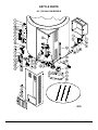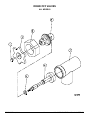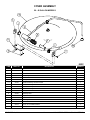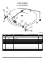
1
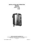
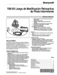
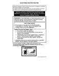
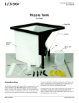
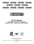
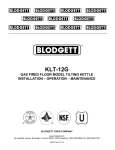
KLS-G SERIES
GAS STATIONARY STEAM JACKETED KETTLE
PARTS AND SERVICE MANUAL
EFFECTIVE NOVEMBER 3, 2015
Superseding All Previous Parts Lists.
The Company reserves the right to make substitution in the event that items specified are not available.
ERRORS: Descriptive and/or typographic errors are subject to correction.
BLODGETT OVEN COMPANY
44 Lakeside Avenue, Burlington, Vermont 05401 USA Telephone: (802) 658-6600 Fax: (802) 860-3732
www.blodgett.com
P/N S00161 Rev A
TABLE OF CONTENTS
GAS SYSTEM ADJUSTMENTS. . . . . . . . . . . . . . . . . . . . . . . . . . . . . . . . . . . . . . . . . . . . . . . . . . . . . . . . . . 3
KETTLE WATER, VACUUM & CONTROL CIRCUIT FUSES.. . . . . . . . . . . . . . . . . . . . . . . . . . . . . . . . 5
CONVERTING BETWEEN NATURAL AND PROPANE GAS. . . . . . . . . . . . . . . . . . . . . . . . . . . . . . . . 6
TROUBLESHOOTING.. . . . . . . . . . . . . . . . . . . . . . . . . . . . . . . . . . . . . . . . . . . . . . . . . . . . . . . . . . . . . . . . . . 7
ILLUSTRATED PARTS LIST
KETTLE PARTS. . . . . . . . . . . . . . . . . . . . . . . . . . . . . . . . . . . . . . . . . . . . . . . . . . . . . . . . . . . . . . . . . . . . . . . . 8
BURNER ASSEMBLY. . . . . . . . . . . . . . . . . . . . . . . . . . . . . . . . . . . . . . . . . . . . . . . . . . . . . . . . . . . . . . . . . 14
DRAW OFF VALVES. . . . . . . . . . . . . . . . . . . . . . . . . . . . . . . . . . . . . . . . . . . . . . . . . . . . . . . . . . . . . . . . . . 16
HINGED COVER ASSEMBLY. . . . . . . . . . . . . . . . . . . . . . . . . . . . . . . . . . . . . . . . . . . . . . . . . . . . . . . . . . 18
COVER ASSEMBLY. . . . . . . . . . . . . . . . . . . . . . . . . . . . . . . . . . . . . . . . . . . . . . . . . . . . . . . . . . . . . . . . . . . 19
COVER ASSEMBLY. . . . . . . . . . . . . . . . . . . . . . . . . . . . . . . . . . . . . . . . . . . . . . . . . . . . . . . . . . . . . . . . . . . 20
MATERIAL SAFETY DATA SHEET.. . . . . . . . . . . . . . . . . . . . . . . . . . . . . . . . . . . . . . . . . . . . . . . . . . . . . 21
DECEMBER 18, 2014
2
KLS-G SERIES STATIONARY GAS KETTLES
GAS SYSTEM ADJUSTMENTS
SAFETY VALVE MAINTENANCE AND TESTING
Manifold Pressure
CAUTION
Under normal operating conditions a “try lever
test” should be performed every two months.
Under severe service conditions, or if corrosion and/or deposits are noticed within the
valve body, testing must be performed more
often. A “try lever test” should also be performed at the end of any non-service period.
Natural Gas
4 inches W.C.
LP Gas
10 inches W.C.
PILOTS
The pilot adjustment is part of the combination control
valve located just behind the lower front access door. It
is located on the center left side of the control just below
the large slotted screw head. Remove the large slotted
screw; below this is a second slotted screw used for adjustment of the pilot burner flame.
CAUTION
Hot, high pressure fluid may be discharged
from body drain and vent during “try lever”
test. Care must be taken to avoid any bodily
contact.
CAUTION
High sound levels may be experienced during
“try lever” test. Wear proper safety equipment and exercise extreme care! Test at, or
near, half of the operating pressure by holding
the test lever fully open for at least two seconds to flush the valve seat free of sediment
and debris. Then release lever and permit the
valve to snap shut.
The front burner shield should be removed to see the pilot. The pilot should be adjusted as follows:
Adjust the pilot burner flame
If lift lever does not activate, or there is no
evidence of discharge, turn off equipment immediately and contact a licensed contractor or
qualified service personnel.
The pilot flame should envelop 3/8 to ½ inch [10 to 13
mm] of the igniter-sensor tip. To adjust the pilot flame:
1. Remove the pilot adjustment cover screw.
2. Turn the inner adjustment screw clockwise to decrease or counterclockwise to increase the pilot
flame.
GENERAL
When any difficulty arises always check that the unit has
been connected to the gas supply type and voltage for
which it was supplied. This can be done by examining
the serial plate on the lower right side of the unit. It will
list the gas type and voltage for which the unit was manufactured.
3. Always replace the cover screw after adjustment and
tighten firmly to ensure proper operation.
Wiring diagrams for the unit are located in a small envelope affixed to the rear side of the front control panel.
UNIT
TOTAL INPUT
ORIFICE SIZE
Natural
Propane
KLS-20G
100,000 BTU/Hour
30
45
KLS-30G
100,000 BTU/Hour
30
45
KLS-40G
100,000 BTU/Hour
30
45
KLS-60G
130,000 BTU/Hour
23
39
KLS-80G
150,000 BTU/Hour
30
45
KLS-100G
150,000 BTU/Hour
30
45
DECEMBER 18, 2014
Pilot Orifice Sizes
3
Natural
0.018 IN
Propane
0.010 IN.
KLS-G SERIES STATIONARY GAS KETTLES
GAS SYSTEM ADJUSTMENTS
GAS PRESSURE REGULATOR
1. Pressure relief valve opening, especially on preheat
from a cold start to 275 degrees Fahrenheit (135°C)
(pressure switch set too high).
The gas pressure regulator is an integral part of the combination gas control located just behind the lower front
access door. The pressure regulator adjustment is on the
lower right side of the gas control. The large slotted cap
must be removed to access the adjustment screw.
2. Burners are being shut down by pressure switch, not
the thermostat. (Pressure switch set too low.)
The pressure switch is preset for proper operation from
the factory. It is adjusted to the maximum pressure, however not high enough to cause the pressure relief valve
to open. This setting will be slightly different on different kettles due to variations in the pressure relief valves.
During preheat to the maximum thermostat setting (275
degrees Fahrenheit) (135°C), from either a cold condition or a lower temperature setting, the temperature may
overshoot the thermostat setting and shut down the burners by the pressure switch. This is normal, however, after
the kettle cycles several times (empty) the thermostat will
begin cycling the unit.
To check the manifold pressure a pressure gauge (manometer) must be connected to the 1/8" NPT pressure
tap on the gas manifold. With the gas off, connect your
pressure indicating instrument to the manifold with a fitting appropriate for your instrument.
1. Turn the unit on; with main burners on, read the manifold pressure. The pressure should be 4 inches water column (W.C.) .2 inches W.C. for natural gas or
10 inches W.C. for propane gas. Adjust the pressure
regulator to obtain the appropriate pressure. Check
serial plate on lower right side of unit to confirm exact
gas type and manifold pressure for your unit.
TO ADJUST PRESSURE SWITCH:
When pressure has been correctly adjusted turn unit off.
Remove pressure indicating instrument and replace the
1/8" NPT plug in manifold. Replace regulator cap and
close access door.
1. To obtain access to the pressure switch, the front
panel must be removed. Remove the screws on either side of the panel. Be sure to support the panel
to avoid excessive strain on the wiring.
THERMOSTAT
2. To increase the pressure setting turn the white ribbed
knob clockwise; to decrease the pressure, turn it
counterclockwise. Use the centre of the black ring
as an indicator.
The thermostat adjustment should not be changed.
Check the following before changing the thermostat:
1. With kettle cool, the pressure reading on the pressure
gauge should be in the green vacuum zone (below 0
psi). If not, see “Re-establishing Vacuum” section.
3. With the kettle empty and completely cold, bypass the
thermostat by moving the single terminal side wire to
the double terminal side connector on the thermostat.
Turn kettle on.
2. Check that the pressure switch is not set too high or
too low and causing the out of adjustment condition.
A voltmeter should be used by a properly trained serviceman to determine if the pressure switch or thermostat is actually cycling the burners. If the pressure switch is found to be the problem, see “Pressure
Switch” section.
4. Pressure in kettle (read pressure gauge on front panel) should reach a maximum of 35 psi and pressure
relief valve should not open. Kettle pressure may rise
3 or 4 psi even after burners shut down.
5. Relief valve should not open when kettle pressure is
40 psi; pressure switch setting is satisfactory.
After verifying that the pressure switch is set and operating properly, the thermostat may be adjusted using the
set screw inside the stem. The thermostat should cycle
off at a gauge pressure reading of 30 psi. Turn set screw
clockwise to decrease pressure and counterclockwise to
increase pressure.
6. If relief valve opens, reduce setting on pressure
switch, cool kettle completely by running cold water
through it and repeat steps 3 - 6.
7. If pressure in kettle is below 30 psi when burners shut
off, increase setting of pressure switch, cool kettle
completely by running cold water through it and repeat steps 3 - 7.
PRESSURE SWITCH
The pressure switch should not be adjusted until it is determined to be the cause of an operating pressure deficiency. See “Thermostat” section to determine if the
source of difficulty is the pressure switch or thermostat.
8. When adjustment is complete, move wire from shorted terminal on the thermostat back to the appropriate
terminal and replace the front panel.
The major difficulties caused by pressure switch mis-adjustment are:
DECEMBER 18, 2014
4
KLS-G SERIES STATIONARY GAS KETTLES
KETTLE WATER, VACUUM & CONTROL CIRCUIT FUSES
ADDING WATER
going to the pressure switch, pressure gauge or thermostat fitting.
It may be necessary to replenish water in the jacket when
the low water indicator comes on. Do so as follows:
CONTROL CIRCUIT FUSES
1. Unit should be completely cold and off.
The control circuit is protected by a 3 amp. fuse which is
located inside control panel, top right side above transformer.
2. Lift handle of pressure relief valve to release vacuum
in kettle. (Relief valve is at right rear of kettle).
Should the unit fail to turn on, check this fuse by removing it and either replacing it or testing it with a continuity
tester. If the fuse is good, check the main power circuit
breaker, which should be external to the kettle.
3. Remove air vent nut on the tee located between kettle and relief valve.
4. Using pure distilled water only, pour the water into
the opening. (A funnel will be helpful). Water will
enter the kettle slowly, as air must escape through the
same hole. Water should be added until the water
level at the sight glass is half way between the minimum and maximum levels.
5. When sufficient water has been added, replace and
tighten the nut.
6. Vacuum must be re-established. (See Re-establishing Vacuum).
For reference, the total amount of distilled water contained in each unit, and amount to be added in a low water condition is listed below:
TOTAL AMOUNT
OF DISTILLED
WATER
AMOUNT OF
WATER TO BE
ADDED IN A
LOW WATER
CONDITION
KLS-20G
4.8 Gallons
155 fl. oz. (4 L)
KLS-40G
6.9 Gallons
236 fl. oz. (7 L)
KLS-60G
9.5 Gallons
338 fl. oz. (10 L)
KLS-80G & KLS100G
16.3 Gallons
721 fl. oz. (10 L)
MODEL
RE-ESTABLISHING VACUUM:
With the kettle completely cold a vacuum of 25 to 30
inches mercury column (M.C.) should be maintained as
indicated in the green zone on the pressure gauge on the
front control panel. If at any time the vacuum is not in the
green zone, vacuum should be re-established.
With the kettle empty, turn the thermostat knob to the
highest temperature. When the temperature pilot light
goes off, open air vent nut one (1) full turn for 20 seconds
and then close and tighten the nut. This should remove
the air and any loss in performance should return.
Should the kettle fail to maintain a vacuum after repeated
attempts to establish it, further checks should be made
to see if the pressure relief valve is leaking or if there are
any leaks in the pressure relief valve piping, copper lines
DECEMBER 18, 2014
5
KLS-G SERIES STATIONARY GAS KETTLES
CONVERTING BETWEEN NATURAL AND PROPANE GAS
WARNING
Fire or explosion hazard can cause property
damage, severe injury, or death.
1. Do not attempt to use a gas control set for
natural gas on propane gas or gas control set
for LP gas on natural gas.
2. When making conversion, main and pilot
burner orifices MUST be changed to meet appliance manufacturer’s specifications.
Standard- or slow-opening gas controls may be converted from one gas to another. To convert from natural gas
to LP use the 393691 LP Conversion Kit that is included
with the VR8304M Gas Control. To convert from LP to
natural gas use the 394588 Natural Gas Conversion Kit
(order separately). Step-opening gas controls cannot be
converted.
To convert control from one gas to another:
1. Turn off main gas supply to the appliance.
2. Remove the regulator cap screw and pressure regulator adjusting screw.
Gas Conversion Kit
3. Remove the existing spring.
4. Insert the replacement spring with tapered end down.
5. Install the new plastic pressure regulator adjustment
screw so that the top of the screw is flush (level) with
the top of the regulator. Turn the pressure regulator
adjustment screw clockwise six complete turns. This
provides a preliminary pressure setting of about 10
inch (254 mm) W.C. for LP regulator and 4 inch (102
mm) W.C. for natural gas regulator.
6. Check the regulator setting either with a manometer
or by clocking the gas meter.
7. Install the new cap screw.
8. Mount conversion label on control.
9. Install control and appliance according to appliance
manufacturer’s instructions.
DECEMBER 18, 2014
6
KLS-G SERIES STATIONARY GAS KETTLES
TROUBLESHOOTING
PROBLEM
Unit will not come on
POSSIBLE CAUSE(S)
- Power switch is off.
- Unit not plugged in.
- Main power supply off.
- Bad electronic module.
- Bad low water control.
- Bad spark igniter.
- Bad intermittent pilot burner.
- Fuse in unit blown.
Unit will turn on electrically but will not heat
- Lockout has occurred.
- Thermostat not on.
- Gas control valve off.
- Main gas supply off.
- Low water.
- Bad thermostat.
- Bad pressure switch.
- Bad gas control valve.
- Bad spark igniter.
- Bad igniter cable.
- Bad intermittent pilot burner.
- Faulty gas control.
Excessive flame rollout on ignition, carboning
- Natural gas unit on propane.
- Excessive gas pressure.
- Incorrect orifice size.
- Faulty regulator in gas control.
Unit slow to preheat and slow to recover
- Propane gas on natural.
- Low gas pressure.
- Incorrect orifice sizes.
- Loss of vacuum.
- Faulty regulator in gas control.
Unit continuously locks out
- Pilot gas adjusted too low.
- Excessive draft condition.
- Excessive steam around bottom of unit during operation of cleaning.
- Faulty transformer.
- Faulty electronic module.
- Faulty ignitor cable.
- Faulty spark igniter.
- Faulty gas control.
DECEMBER 18, 2014
7
KLS-G SERIES STATIONARY GAS KETTLES
KETTLE PARTS
20 - 60 GALLON MODELS
DECEMBER 18, 2014
8
KLS-G SERIES STATIONARY GAS KETTLES
KETTLE PARTS
20 - 60 GALLON MODELS
ITEM
PART NO.
1
40453
DESCRIPTION
Elbow, 1/4 C x 1/4 FPT
QUANTITY
20
30
40
60
1
1
1
1
2
40542
Level Control
1
1
1
1
3
41333
Component Mounting Bracket
1
1
1
1
4
41861
Fuse, 3 Amp., 250V
1
1
1
1
5
41863
Fuse Holder
1
1
1
1
6
40046
Thermostat
1
1
1
1
7
40033
Recess Control Panel
1
1
1
1
* **
42548
Control Decal - English
1
1
1
1
* **
42475
Control Decal - French
1
1
1
1
8
41889
Power Switch
1
1
1
1
9
43391
Pilot Light - 28 Volt, Red Cooking
1
1
1
1
10
42429
Pilot Light - 125 V, Amber - Low Water
1
1
1
1
11
41006
Thermostat Dial
1
1
1
1
12
40815
Pressure Gauge Bracket
1
1
1
1
13
40907
Pressure Gauge
1
1
1
1
14
40022
Support Bracket
1
1
1
1
15
42443
Pressure Switch
1
1
1
1
16
40456
Tee, 1/4 C x 1/8 MPT
1
1
1
1
17
41077
Sight Glass Assembly
1
1
1
1
*
41877
Sight Glass
1
1
1
1
*
42434
Washer
2
2
2
2
*
--
Brass Washer
2
2
2
2
*
--
Rods
2
2
2
2
18
42440
Tee, 3/8" - 3000 lb
1
1
1
1
19
40425
Connector 1/4 C x 3/8 MPT
1
1
1
1
20
41474
Adjustable Foot
3
3
3
3
1
1
1
1
1
1
1
21
40058
Door Knob
1
22
40038
Access Door Assembly
1
40039
Access Door Assembly
40040
Access Door Assembly
40049
Door Hinge
1
40062
Corner Front Panel
1
40063
Corner Front Panel
40064
Corner Front Panel
--
Corner Front Panel
1
1
1
1
40663
Cord Set, 120V
1
41241
Front Shield
1
41245
Front Shield
40035
Manifold Assembly
1
41813
Pipe Plug, 1/8 NPT
40709
Pilot Bracket
DECEMBER 18, 2014
1
9
1
1
1
1
1
1
1
1
1
1
1
1
1
1
1
1
KLS-G SERIES STATIONARY GAS KETTLES
KETTLE PARTS
20 - 60 GALLON MODELS
ITEM
**
**
**
**
*
*
PART NO.
QUANTITY
DESCRIPTION
20
30
40
60
40723
Pilot Bracket
1
42349
Ignitor/Sensor Pilot, Natural
1
1
1
1
42350
Ignitor/Sensor Pilot, LP
1
1
1
1
41039
Ignitor Cable
1
1
1
1
42401
Burner Orifice # 30, Natural Gas
2
2
2
42402
Burner Orifice # 45, LP
2
2
2
42403
Burner Orifice # 26, Natural Gas
42404
Burner Orifice # 41, LP
41797
Union, 1/2 NPT
1
1
1
1
41108
Combination Gas Control, Natural Gas
1
1
1
1
1
1
1
2
2
41109
Combination Gas Control, LP
1
40320
Burner
2
41045
Combination Gas Control – Natural, 120V after 10/27/05
1
1
1
1
41046
Combination Gas Control – LP, 120V after 10/27/05
1
1
1
1
40321
Burner
2
2
40322
Burner
41773
Close Nipple, 1/2
1
1
1
1
40431
Connector, 3/8 C x 3/8 MPT
2
2
2
2
40417
Connector, 3/8 C x 3/8 FPT
2
2
2
2
40708
Terminal Block
2
2
2
2
40707
End Section
1
1
1
1
42269
Gas Flex Hose
1
1
1
1
40466
Probe, 9-3/4"
1
40467
Probe, 9-1/4"
1
1
1
41794
Tee, 3/4 x 3/4 x 3/8
1
1
1
1
41791
St. Elbow, 3/4"
1
1
1
1
41044
Down Tube
1
1
1
1
43392
Air Vent
1
1
1
1
40613
Relief Valve
1
1
1
1
1
1
1
2
40287
Flue Box
40288
Flue Box
40289
Flue Box
40054
Faucet Bracket
1
1
1
1
41885
Transformer, 115/230 - 24V, 50/60 Hz, 50 VA
1
1
1
1
1
42351
Ignition Module Kit
1
1
1
1
*
43393
Lighting Instructions
1
1
1
1
*
--
Pilot Tube, 1/4" x 20"
1
1
1
1
*
--
Bottom Cover
1
--
Bottom Cover
1
1
--
Bottom Cover
* NOT SHOWN.
1
** SELECT AS REQUIRED.
1G-00005 Wiring Diagram, 120V
DECEMBER 18, 2014
1G-00006 Wiring Diagram, 208 - 240V
10
KLS-G SERIES STATIONARY GAS KETTLES
KETTLE PARTS
80 - 100 GALLON MODELS
DECEMBER 18, 2014
11
KLS-G SERIES STATIONARY GAS KETTLES
KETTLE PARTS
80 - 100 GALLON MODELS
QUANTITY
ITEM
PART NO.
80
100
1
41249
Flue Box Assembly
1
1
2
40548
Air Vent
1
1
3
41861
Fuse 3A, 250V
1
1
4
41863
Fuse Holder
1
1
5
40612
Relief Valve, 35 psi
1
1
6
40542
Level Control
1
1
7
40033
Control Panel
1
1
** 8
42548
English Label
1
1
42475
French Label
1
1
41093
Ignition Module DSI 3 Trial Ignition
1
1
9
DESCRIPTION
10
42457
Power Switch
1
1
11
40046
Thermostat
1
1
12
43486
Pressure Gauge Bracket
1
1
13
43240
Pilot Light, Cooking, Red, 28V
1
1
14
43487
Pressure Switch
1
1
15
40907
Pressure Gauge
1
1
16
43488
Pilot Light, Low Water, Amber, 120V
1
1
17
41006
Dial
1
1
18
43241
Pressure Switch Bracket
1
1
19
41474
Leg Adjustable Pad Assembly
4
4
20
40001
Front Panel
1
40000
Front Panel
21
41228
Access Door
1
1
** 22
41108
Combination Gas Control - Natural Gas
1
1
1
41109
Combination Gas Control - Propane
1
1
41045
Combination Gas Control – Natural, 120V for units after 10/27/05
1
1
41046
Combination Gas Control – LP, 120V for units after 10/27/05
1
1
23
42860
Bottom Cover
1
1
24
41855
Gas Flex Hose, 3/4" x 18"
1
1
25
43489
Burner Basket Shield/Bracket
1
1
26
41077
Sight Glass Assembly
1
1
41877
Gauge Glass, 5/8 x 4-3/4
1
1
41743
Washers
2
2
41744
Brass Washer
2
2
41741
Rod
2
2
27
40707
Terminal Block End Section
1
1
28
40708
Terminal Block Section
2
2
29
41027
Low Water Probe
1
1
30
41333
Component Mounting Bracket
1
1
31
43490
Burner Shield
1
1
32
42706
Cord Set, 120V
1
1
DECEMBER 18, 2014
12
KLS-G SERIES STATIONARY GAS KETTLES
KETTLE PARTS
80 - 100 GALLON MODELS
ITEM
PART NO.
33
--
QUANTITY
DESCRIPTION
Elbow 90°, Brass 1/4C x 1/4 FPT
80
100
1
1
34
--
Door Knob
1
1
35
--
Access Door Pivot Rod
1
1
36
--
Brass Pipe Nipple, 3/8 x 2 Lg.
1
1
37
--
Forged Tee, C.S. 3000 # 3/8 NPT
1
1
38
--
Connector, Brass, 1/4 C x 3/8 MPT
1
1
39
--
Black Pipe Close Nipple, ½ NPT
1
1
40
--
Black Pipe Nipple, 3/4 - SCH. 40 x 3-1/2" Lg.
1
1
41
--
Tee, Black Iron 150# 3/4 x 3/4 x 3/8 NPT
1
1
42
--
Street Elbow 90°, Black Iron 150 # 3/4" NPT
2
2
43
--
Extension, Relief Valve
1
1
44
--
Transformer, 120/24V, 50VA
1
1
* 45
43494
Faucet Bracket, Optional
1
1
* ** 46
40991
Transformer 240-120V, 100VA (220/240V Units)
1
1
* NOT SHOWN.
** SELECT AS REQUIRED
DECEMBER 18, 2014
13
KLS-G SERIES STATIONARY GAS KETTLES
BURNER ASSEMBLY
80-100 GALLON MODELS
DECEMBER 18, 2014
14
KLS-G SERIES STATIONARY GAS KETTLES
BURNER ASSEMBLY
80-100 GALLON MODELS
ITEM
PART NO.
40322
DESCRIPTION
QUANTITY
Burner
3
2
--
Pilot Bracket
1
3
--
Cover, Igniter Wiring
1
4
43491
Burner Basket
1
5
40387
Orifice #45, L.P.
3
40383
Orifice #30, Natural Gas
3
6
43492
Gas Manifold
1
7
41813
Sq. Hd. Pipe Plug 1/8 NPT
1
8
40617
Union Elbow, 3/4 NPT
1
9
41796
Reducing Elbow, #150, ½ NPT
1
10
43493
Igniter Cable
1
** 11
43331
Igniter/Sensor Pilot, Natural
1
--
Igniter/Sensor Pilot, LP
1
--
Insulation, 1.00" x 7.450" x 1.50"
1
* 12
* NOT SHOWN
** SELECT AS REQUIRED.
DECEMBER 18, 2014
15
KLS-G SERIES STATIONARY GAS KETTLES
DRAW OFF VALVES
ALL MODELS
DECEMBER 18, 2014
16
KLS-G SERIES STATIONARY GAS KETTLES
DRAW OFF VALVES
ALL MODELS
ITEM
PART NO.
40553
DESCRIPTION
QUANTITY
1-1/2" DRAW-OFF VALVE ASSEMBLY
1
41809
Acorn Nut 10-24 UNC
1
2
40662
Handle, Stainless Steel
1
3
40559
Gland Nut
1
4
40560
Bonnet
1
5
40562
“O” Ring
1
6
40561
Stem Assembly
1
7
43246
Valve Body
1
40554
2" DRAW-OFF VALVE ASSEMBLY
1
41809
Acorn Nut 10-24 UNC
1
2
40662
Handle, Stainless Steel
1
3
40563
Gland Nut
1
4
40564
Bonnet
1
5
40566
“O” Ring
1
6
40565
Stem Assembly
1
7
42481
Valve Body
1
40556
3" DRAW-OFF VALVE ASSEMBLY
1
40567
Acorn Nut, 7/16-14 UNC
1
2
40568
Handle, Stainless Steel
1
3
40569
Gland Nut
1
4
40570
Bonnet
1
5
40572
“O” Ring
1
6
40571
Stem Assembly
1
7
43248
Valve Body
1
DECEMBER 18, 2014
17
KLS-G SERIES STATIONARY GAS KETTLES
HINGED COVER ASSEMBLY
20 - 60 GALLON MODELS
ITEM
PART NO.
DESCRIPTION
QUANTITY
40259
Knob
1
**2
42167
Handle Assembly, 20 Gallon Kettle
1
42168
Handle Assembly, 30 or 40 Gallon Kettle
1
3
40109
Hex Bolt, 1/2 - 20 UNF x 1" S.S.
2
4
40133
Fibre Washer
4
5
40111
Hex Nut, 1/2 - 20 UNF, S.S.
2
6
--
Split Lock Washer, 1/2", S.S.
2
**7
--
Cover, 20 Gallon Kettle
1
--
Cover, 30 or 40 Gallon Kettle
1
** SELECT AS REQUIRED
DECEMBER 18, 2014
18
KLS-G SERIES STATIONARY GAS KETTLES
COVER ASSEMBLY
20 - 60 GALLON MODELS
ITEM
PART NO.
DESCRIPTION
QUANTITY
42112
HINGE ASSEMBLY
1
41543
Lock Pin
1
2
41546
End Lock Plate
1
3
43106
Stationary Disc
1
4
41100
Core
1
5
41526
Spring
1
** 6
41540
Handle Assembly, 20 Gallon Kettle
1
--
Handle Assembly, 30 Gallon Kettle
1
41541
Handle Assembly, 40 Gallon Kettle
1
41532
Handle Assembly, 60 Gallon Kettle
1
7
43107
Rotary Disc
1
8
41520
End Stop Plate
1
9
40098
Cap Screws, 1/4-20 x 3/4
4
10
40259
Knob
1
11
40462
Mounting Plate
1
**12
40017
Cover, 20 Gallon Kettle
1
41514
Cover, 30 or 40 Gallon Kettle
1
41515
Cover, 60 Gallon Kettle
1
** SELECT AS REQUIRED
DECEMBER 18, 2014
19
KLS-G SERIES STATIONARY GAS KETTLES
COVER ASSEMBLY
80 - 100 GALLON MODELS
ITEM
PART NO.
DESCRIPTION
QUANTITY
42112
COVER ASSEMBLY
1
41543
Lock Pin
1
2
41546
End Lock Plate
1
3
43106
Stationary Disc
1
4
41100
Core
1
5
41526
Spring
1
6
42464
Handle Assembly
1
7
43107
Rotary Disc
1
8
41520
End Stop Plate
1
9
40098
Cap Screws, 1/4 - 20 x 3/4, Stainless Steel
4
10
40259
Knob
1
40462
Mounting Plate
1
42467
Cover
1
11
DECEMBER 18, 2014
20
KLS-G SERIES STATIONARY GAS KETTLES
MATERIAL SAFETY DATA SHEET
PREPARATION INFORMATION:
Prepared for use in Canada by: E H & S Product Regulatory Management Department
DOW CHEMICAL CANADA INC.
P.O. Box 1012
Sarnia, Ontario, N7T 7K7
(800) 331-6451
CHEMICAL PRODUCT AND COMPANY IDENTIFICATION
IN CASE OF EMERGENCY:
Fort Saskatchewan, Alberta: (780) 998-8282
Sarnia, Ontario: (519) 339-3711
Varennes, Quebec: (450) 652-1000
Product:............................. DOWFROSTTM HD HEAT TRANSFER FLUID, DYED
Product Code:
04632
Effective Date:
2/20/01
Date Printed: 07/10/02
MSD: 002239
DOW CHEMICAL CANADA INC.
P.O. Box 1012
Sarnia, Ontario, N7T 7K7
Prepared for use in Canada by the E H & S Product Regulatory Management Department; Phone: (800) 331-6451.
COMPOSITION/INFORMATION ON INGREDIENTS
Propylene Glycol
CAS # 000057-55-6
94%
Dipotassium Phosphate
CAS # 007758-11-4
<5%
Deionized Water
CAS # 007732-18-5
<5%
DECEMBER 18, 2014
21
KLS-G SERIES STATIONARY GAS KETTLES
MATERIAL SAFETY DATA SHEET
Product: DOWFROSTTM HD HEAT TRANSFER FLUID, DYED
Product Code: 04632
Effective Date: 02/20/01, Date Printed: 07/10/02, MSD: 002239
HAZARDS IDENTIFICATION
EMERGENCY OVERVIEW
Clear yellow liquid. Odourless. Avoid temperatures above 450°F, 232°C.
POTENTIAL HEALTH EFFECTS (See Section 11 for toxicological data.)
EYE: May cause slight transient (temporary) eye irritation. Corneal injury is unlikely. Mists may cause eye irritation.
SKIN CONTACT: Prolonged contact is essentially nonirritating to skin. A single prolonged exposure is not likely to result in
the material being absorbed through skin in harmful amounts. Repeated exposures may cause flaking and softening of skin.
INGESTION: Single dose oral toxicity is considered to be extremely low. No hazards anticipated from swallowing small
amounts incidental to normal handling operations.
INHALATION: At room temperature, vapours are minimal due to physical properties. Mists may cause irritation of upper
respiratory tract (nose and throat).
SYSTEMIC (OTHER TARGET ORGAN) EFFECTS: Repeated excessive exposure to propylene glycol may cause central
nervous system effects.
CANCER INFORMATION: Did not cause cancer in laboratory animals.
TERATOLOGY (BIRTH DEFECTS): Birth defects are unlikely. Exposures having no adverse effects on the mother should
have no effect on the fetus.
REPRODUCTIVE EFFECTS: In animal studies, has been shown not to interfere with reproduction.
TM indicates a trademark of The Dow Chemical Company.
DECEMBER 18, 2014
22
KLS-G SERIES STATIONARY GAS KETTLES
MATERIAL SAFETY DATA SHEET
Product: DOWFROSTTM HD HEAT TRANSFER FLUID, DYED
Product Code: 04632
Effective Date: 02/20/01, Date Printed: 07/10/02, MSD: 002239
FIRST AID
EYES:
Flush eyes with plenty of water.
SKIN:
Wash off in flowing water or shower.
INGESTION:
No adverse effects anticipated by this route of exposure incidental to proper industrial handling.
INHALATION:
Remove to fresh air if effects occur. Consult a physician.
NOTE TO PHYSICIAN:
No specific antidote. Supportive care. Treatment based on judgment of the physician in response
to reactions of the patient.
FIRE FIGHTING MEASURES
FLAMMABLE PROPERTIES
FLASH POINT:
214°F, 107°C (based on a similar material)
METHOD USED:
PMCC
AUTOIGNITION TEMPERATURE: Not determined.
FLAMMABILITY LIMITS
LFL: Not determined.
UFL: Not determined
DECEMBER 18, 2014
23
KLS-G SERIES STATIONARY GAS KETTLES
MATERIAL SAFETY DATA SHEET
Product: DOWFROSTTM HD HEAT TRANSFER FLUID, DYED
Product Code: 04632
Effective Date: 02/20/01 Date Printed: 07/10/02, MSD: 002239
HAZARDOUS COMBUSTION PRODUCTS: During a fire, smoke may contain the original material in addition to unidentified toxic and/or irritating compounds. Hazardous combustion products may include and are not limited to carbon monoxide
and carbon dioxide.
OTHER FLAMMABILITY INFORMATION: Violent steam generation or eruption may occur upon application of direct water
stream to hot liquids. Flammable concentrations of vapour can accumulate at temperatures above 214°F. Liquid mist of this
product can burn. Spills of these organic liquids on hot fibrous insulations may lead to lowering of the autoignition temperatures possibly resulting in spontaneous combustion. Container may rupture from gas generation in a fire situation.
EXTINGUISHING MEDIA: Water fog or fine spray, carbon dioxide, dry chemical, foam. Alcohol resistant foams (ATC type)
are preferred if available. General purpose synthetic foams (including AFFF) or protein foams may function, but much less
effectively. Do not use direct water stream. May spread fire.
MEDIA TO BE AVOIDED: Do not use direct water stream.
FIRE FIGHTING INSTRUCTIONS: Keep people away. Isolate fire area and deny unnecessary entry. Burning liquids may
be moved by flushing with water to protect personnel and minimize property damage. Burning liquids may be extinguished
by dilution with water. Do not use direct water stream. May spread fire. Fight fire from protected location or safe distance.
Consider use of unmanned hose holder or monitor nozzles. Use water spray to cool fire exposed containers and fire affected zone until fire is out and danger of re-ignition has passed. Immediately withdraw all personnel from area in case of
rising sound from venting safety device or discolouration of the container. Move container from fire area if this is possible
without hazard.
PROTECTIVE EQUIPMENT FOR FIRE FIGHTERS: Wear positive-pressure self-contained breathing apparatus (SCBA)
and protective fire fighting clothing (includes fire fighting helmet, coat, pants, boots and gloves). If protective equipment is
not available or not used, fight fire from a protected location or safe distance.
DECEMBER 18, 2014
24
KLS-G SERIES STATIONARY GAS KETTLES
MATERIAL SAFETY DATA SHEET
Product: DOWFROSTTM HD HEAT TRANSFER FLUID, DYED
Product Code: 04632
Effective Date: 02/20/01, Date Printed: 07/10/02, MSD: 002239
ACCIDENTAL RELEASE MEASURES (See Section 15 for Regulatory Information)
PROTECT PEOPLE: Use appropriate safety equipment. For additional information, refer to Section 8, Exposure Controls/
Personal Protection.
PROTECT THE ENVIRONMENT: Avoid contamination of all waterways.
CLEAN-UP: See Section 13, Disposal Consideration.
HANDLING AND STORAGE
SPECIAL PRECAUTIONS TO BE TAKEN IN HANDLING AND STORAGE: No special handling requirements data available.
HANDLING: See Section 8, Exposure Controls/Personal Protection. STORAGE: See Section 10, Stability and Reactivity.
STORAGE: See Section 10, Stability and Reactivity.
EXPOSURE CONTROLS/PERSONAL PROTECTION
ENGINEERING CONTROLS: Provide general and/or local exhaust ventilation to control airborne levels below the exposure
guidelines.
PERSONAL PROTECTIVE EQUIPMENT
EYE/FACE PROTECTION: Use safety glasses. Safety glasses should be sufficient for most operations; however, for misty
operations wear chemical goggles.
SKIN PROTECTION: Use gloves impervious to this material.
RESPIRATORY PROTECTION: Atmospheric levels should be maintained below the exposure guideline. When respiratory
protection is required for certain operations, use an approved air-purifying respirator. In misty atmospheres, use an approved mist respirator.
EXPOSURE GUIDELINES: Propylene glycol: AIHA WEEL is 50 ppm total, 10 mg/m3 aerosol only.
DECEMBER 18, 2014
25
KLS-G SERIES STATIONARY GAS KETTLES
MATERIAL SAFETY DATA SHEET
Product: DOWFROSTTM HD HEAT TRANSFER FLUID, DYED
Product Code: 04632
Effective Date: 02/20/01, Date Printed: 07/10/02, MSD: 002239
PHYSICAL AND CHEMICAL PROPERTIES
APPEARANCE/PHYSICAL STATE:.......................................... Clear yellow liquid.
ODOUR:.................................................................................................. Odourless
VAPOUR PRESSURE:............................................................ 0.22 mmHg @ 20°C
VAPOUR DENSITY:........................................................................................... 2.6
BOILING POINT:................................................................................ 320°F, 160°C
SOLUBILITY IN WATER/MISCIBILITY:.................................................... Complete
SPECIFIC GRAVITY OR DENSITY:.............................................1.058 @ 25/25°C
STABILITY AND REACTIVITY
CHEMICAL STABILITY: Thermally stable at typical use temperatures.
CONDITIONS TO AVOID: Avoid use temperatures above 450°F, 232°C. Product can degrade at elevated temperatures.
Generation of gas during decomposition can cause pressure in closed systems.
INCOMPATIBILITY WITH OTHER MATERIALS: Avoid contact with oxidizing materials. Avoid contact with strong acids
HAZARDOUS DECOMPOSITION PRODUCTS: Hazardous decomposition products depend upon temperature, air supply
and the presence of other materials.
HAZARDOUS POLYMERIZATION: Will not occur.
TOXICOLOGICAL INFORMATION (See Section 3 for Potential Health Effects. For detailed toxicological data, write or call
the address or non-emergency number shown in Section 1).
SKIN: The LD50 for skin absorption in rabbits is >10,000 mg/kg.
DECEMBER 18, 2014
26
KLS-G SERIES STATIONARY GAS KETTLES
MATERIAL SAFETY DATA SHEET
Product: DOWFROSTTM HD HEAT TRANSFER FLUID, DYED
Product Code: 04632
Effective Date: 02/20/01, Date Printed: 07/10/02, MSD: 002239
INGESTION: The oral LD50 for rats is 20,000 - 34,000 mg/kg.
MUTAGENICITY: In vitro mutagenicity studies were negative. Animal mutagenicity studies were negative.
ECOLOGICAL INFORMATION (For detailed Ecological data, write or call the address or non-emergency number shown
in Section 1.)
ENVIRONMENTAL FATE
MOVEMENT & PARTITIONING: Based largely or completely on data for major component(s). Bioconcentration potential is
low (BCF less than 100 or Log Pow less than 3). Potential for mobility in soil is very high (Koc between 0 and 50).
DEGRADATION AND PERSISTENCE: Based largely or completely on data for major component(s). Material is readily
biodegradable. Passes OECD test(s) for ready biodegradability. Degradation is expected in the atmospheric environment
within minutes to hours.
ECOTOXICITY: Based largely or completely on data for major component(s). Material is practically non-toxic to aquatic
organisms on an acute basis (LC50/EC50 >100 mg/L in most sensitive species).
DISPOSAL CONSIDERATIONS (See Section 15 for Regulatory Information)
DISPOSAL: DO NOT DUMP INTO ANY SEWERS, ON THE GROUND OR INTO ANY BODY OF WATER. All disposal
methods must be in compliance with all Federal, State/Provincial and local laws and regulations. Regulations may vary in
different locations. Waste characterizations and compliance with applicable laws are the responsibility solely of the waste
generator. THE DOW CHEMICAL COMPANY HAS NO CONTROL OVER THE MANAGEMENT PRACTICES OR MANUFACTURING PROCESSES OF PARTIES HANDLING OR USING THIS MATERIAL. THE INFORMATION PRESENTED
HERE PERTAINS ONLY TO THE PRODUCT AS SHIPPED IN ITS INTENDED CONDITION AS DESCRIBED IN MSDS
SECTION 2 (Composition/Information On Ingredients).
DECEMBER 18, 2014
27
KLS-G SERIES STATIONARY GAS KETTLES
MATERIAL SAFETY DATA SHEET
Product: DOWFROSTTM HD HEAT TRANSFER FLUID, DYED
Product Code: 04632
Effective Date: 02/20/01, Date Printed: 07/10/02, MSD: 002239
FOR UNUSED & UNCONTAMINATED PRODUCT, the preferred options include sending to a licensed, permitted: recycler,
reclaimer, incinerator or other thermal destruction device.
As a service to its customers, Dow can provide names of information resources to help identify waste management companies and other facilities which recycle, reprocess or manage chemicals or plastics, and that manage used drums. Telephone
Dow’s Customer Information Center at 800-258-2436 or 989-832-1556 for further details.
TRANSPORT INFORMATION
DEPARTMENT OF TRANSPORTATION (D.O.T.): For D.O.T. regulatory information, if required, consult transportation regulations, product shipping papers, or contact your Dow representative.
CANADIAN TDG INFORMATION: For TDG regulatory information, if required, consult transportation regulations, product
shipping papers, or your Dow representative.
REGULATORY INFORMATION (Not meant to be all-inclusive – selected regulations represented).
NOTICE: The information herein is presented in good faith and believed to be accurate as of the effective date shown
above. However, no warranty, express or implied is given. Regulatory requirements are subject to change and may differ
from one location to another; it is the buyer’s responsibility to ensure that its activities comply with federal, state or provincial, and local laws. The following specific information is made for the purpose of complying with numerous federal, state or
provincial, and local laws and regulations. See other sections for health and safety information.
DECEMBER 18, 2014
28
KLS-G SERIES STATIONARY GAS KETTLES
MATERIAL SAFETY DATA SHEET
Product: DOWFROSTTM HD HEAT TRANSFER FLUID, DYED
Product Code: 04632
Effective Date: 02/20/01, Date Printed: 07/10/02, MSD: 002239
U.S. REGULATIONS
SARA 313 INFORMATION: To the best of our knowledge, this product contains no chemical subject to SARA Title III Section
313 supplier notification requirements.
SARA HAZARD CATEGORY: This product has been reviewed according to the EPA “Hazard Categories” promulgated under Sections 311 and 312 of the Superfund Amendment and Reauthorization Act of 1986 (SARA Title III) and is considered,
under applicable definitions, to meet the following categories:
Not to have met any hazard category.
TOXIC SUBSTANCES CONTROL ACT (TSCA):
All ingredients are on the TSCA inventory or are not required to be listed on the TSCA inventory.
STATE RIGHT-TO-KNOW: The following product components are cited on certain state lists as mentioned. Non-listed components may be shown in the composition section of the MSDS.
CHEMICAL NAME
CAS NUMBER
LIST
1, 2-Propanediol
000057-55-6
PA1
PA1= Pennsylvania Hazardous Substance (present at greater than or equal to 1.0%).
OSHA HAZARD COMMUNICATION STANDARD: This product is not a “Hazardous Chemical” as defined by the OSHA
Hazard Communication Standard, 29 CFR 1910.1200.
DECEMBER 18, 2014
29
KLS-G SERIES STATIONARY GAS KETTLES
MATERIAL SAFETY DATA SHEET
Product: DOWFROSTTM HD HEAT TRANSFER FLUID, DYED
Product Code: 04632
Effective Date: 02/20/01, Date Printed: 07/10/02, MSD: 002239
CANADIAN REGULATIONS
WHMIS INFORMATION: The Canadian Workplace Hazardous Materials Information System (WHMIS) Classification for
this product is:
This product is not a “Controlled Product” under WHMIS. CANADIAN ENVIRONMENTAL PROTECTION ACT (CEPA)
CANADIAN ENVIRONMENTAL PROTECTION ACT (CEPA)
This product contains one or more substances which are not listed on the Canadian Domestic Substances List (DSL). Contact your Dow representative for more information.
OTHER INFORMATION
MSDS STATUS: Revised Section 8 (Exposure Guidelines).
The information herein is given in good faith, but no warranty, express or implied, is made. Consult The Dow Chemical
Company for further information.
DECEMBER 18, 2014
30
KLS-G SERIES STATIONARY GAS KETTLES