1
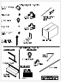
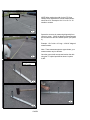
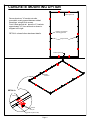
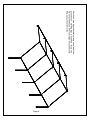
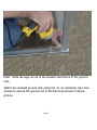
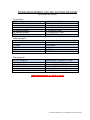
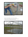
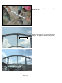
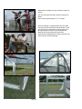
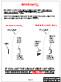
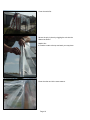
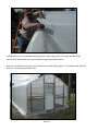
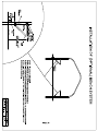
Carver
Premium Commercial Greenhouse
Assembly Manuals for Models:
10'(w) x 16'(d) x 8'(h)
10'(w) x 27'(d) x 8'(h)
Customer Service: (877) 373-3078 Email: [email protected]
65 Fleetwood Drive, Rockaway, NJ 07866
PARTS DESCRIPTION
/8 "
15
X
1" X 2" GROUND
RAIL WITH
WELDED
STANCHIONS
"
5'1
IN
RL
PU
/8"
15
X
"
5'1
RA
FT
ER
/8"
15
1" X 2" X 10'
RECTANGLE
TUBING FOR
ENDWALL
GROUND RAIL
X
S
EG
"L
5'1
2" X 2"
SQUARE
TUBING USED
FOR STUDS AND
ENDWALL
FRAMING
3 WAY CONNECTOR
4 WAY CONNECTOR
PAGE 1
Ground Rails
NOTE:When setting the width for the E-Z Grow
Hobby House theOutside to outside measurement
should be 10' 4".Eaxample 10 X 16 is 10' 4" X 16'
outside to outside.
1
Square the structure by measuring diagonally from
corner to corner . When the diagonal measurements
are the same the structure will be square. (see photo
2.)
Example: 10'-4" wide x 16' long = 19'-9/16" diagonal
measurements.
Note: These measurements are approximate, your
measurements may be different.
2
Once the ground rails are squared anchor the rails
using the 12" spiked provided as shown in photo
3,4&5..
If on ground
use12" spike.
3
5
4
PAGE 3
CONCRETE MOUNTING OPTION
front/rear ground rail
Secure aluminum "z'' bracket onto side
groundrails, evenly spaced between welded
stanchions, using #14 tek screws.
Front & Rear ground rail: place the ''z'' brackets
approximately 16'' from each end as shown in
diagram to the right.
aluminum "z" bracket for
anchoring ground rail
DETAIL A. shows further attachment details.
side ground rails
front/rear ground rail
welded
stanchions
DETAIL A.
tek
screws
1
4''
concrete
drive pins
ground rail (sides or ends)
Page 4
4-way
connector
purlin (5'-1'')
Rafter(5'-1")
Leg (5'-1'')
purlin (5'-1'')
ASSEMBLING THE FRAME
1. Identify 3-way & 4-way connectors. 3-way connectors are for the ends and 4-way connectors are for intermediate
rafters, legs and at the peak of greenhouse.
Assemble frame as shown in below diagram. DO NOT assemble legs at this time, completed frame must be lifted and
placed on the legs then onto anchor posts.
2.
3-way
connector
3-way
connector
ALL PURLIN, RAFTERS AND
LEGS ARE THE SAME LENGTH.
Position 2 men approximately along one side of the
greenhouse. Holding legs in one hand, lift up one
side of greenhouse and insert legs into connectors.
Repeat on the other side.
Page 5
Note: Slide the legs on top of the welded stanchions of the ground
rails.
Attach the endwall ground rails using the 3x 3 L-brackets. Use Tekscrews to secure the ground rail to the frame as shown in above
picture.
Page 9
OPENING MEASUREMENTS FOR FANS, SHUTTERS AND DOORS
{SUPPLIED BY ATLAS}
Fan opening for:
18” Box wall “Quietaire”
30” Slant wall “Quietaire”
36” Box wall “Quietaire”
36” Slant wall “Quietaire”
42” Slant wall “Quietaire”
48” Slant wall “Quietaire”
56” Slant wall “Quietaire”
24 1/2” High X 24 1/2” Wide
35 5/8” High X 34 3/4" Wide
40 1/2” High X 40 1/2” Wide
42 1/4" High X 41” Wide
48 1/2” High X 47” Wide
54 1/4” High X 52 3/4” Wide
65” High X 63” Wide
Shutter openings for:
24” Shutter
30” Shutter
39” Shutter
45” Shutter
48” Shutter
60” Shutter
24 1/2” Square
30 1/2” Square
39 1/2” Square
45 1/2” Square
48 1/2” Square
60 1/2” Square
Door openings for:
42” X 6’6” Swing door
4’ X 6’8’’ Swing Door
36” X 6’8” Swing door
6’ X 6’8’’ French Door
4’ X 7’ Single Sliding door
8’ X 7’ Double slide door
Set openings 42 1/2” Wide X 78 1/2” High
Set openings 48 1/2” Wide X 80” High
Set openings 36” Wide X 80” High
Set openings 72” Wide X 80” High
Set openings 46” Wide X 82” High
Set openings 96” Wide X 82” High
NOTE: Measurements are inside to inside.
All of the above listed items may not be available for your particular structure.
Frame out the door 30-1/2" wide x 72-1/4" high.
30-1/2"
X
72-1/4"
1.
Square clamp
End wall framing attaches to the bow using a round
clamp on the bow and a square clamp on the 2"x2"
stud. See photo 2.
Round clamp
2.
3.
PAGE11
Attach the 2" x 2" studs to the end ground rail using
3" x 3" L-bracket as shown.
The Shutter opening is 24-1/2"Wide x 24-3/4" High.
Attach horizontal 2x2 using L-brackets as shown.
Note the L brackets will attach on the outside of any openings.
Example: On top of the door header, on bottom of the lower horizontal
for shutter and on top of the upper horizontal for shutter.
Page 12
You must field cut the ridge purlin to exact length of
the ground rails.
Attach ridge purlin with Tek-screws and two hole
clamps. The ridge purlin attaches under all bows.
Two hole clamp
PAGE 13
The ridge purlin is connected under all bows
using 2-hole clamps.
Ridge Purlin 1-3/8"
Prepare to attach wire lock base to the top of
the end bows, around the openings and
around the base of the greenhouse.
Side Purlin With Optional
Wirelock Base.
OPTIONAL Cutrain will require wire lock on
the Side Purlins at the eave.
Wire lock at base of
greenhouse
Page 14
If you ordered the optional curtain system,
attach the curtain channel approximately 28"
above the ground rail. (See photo #1).
1
Approx. 28" from
top of groundrail.
Curtain Chanel
When framing is complete, wire lock base will be
attached on top of the end bows as shown in
pictures 4 & 5. The wire lock base will go from
the bottom of the ground rail over the end bow,
down to the curtain channel, then from the
curtain channel down to the bottom of the
ground rail as seen in picture 2.
2
Wire Lock Base
Identify the curtain crank rod. Attach wire lock
base along the length of the crank rod.
3
4
5
Page 15
Attach Wire Lock Base over the end bows using Tekscrews.
The wire lock base will bend over the curvatures as
shown.
Place screws approximately 12" to 16" apart.
Once the framing is complete attach wire lock base
over the top of each end bow from the bottom of the
ground rail over to the bottom of the gground rail on
the opposite side as shown. Wire lock base also
attaches all the way around the base of the
greenhouse screwing directly to the ground rails, and
around all door and fan openings.
Page 16
IMPORTANT
NEVER APPLY POLY TOO
LOOSELY. IF POLY IS LOOSE, IT
WILL SAG BETWEEN FRAMING
MEMBERS AND “POCKET” WATER
AND /OR SNOW. THIS MAY RESULT
IN SEVERE STRUCTURAL DAMAGE
Page 17
Cover the ends first .
Secure the poly in place by wiggling the wire into the
channel as shown.
Helpful Hint:
It is easier to start at the top and work your way down.
Cover the other end in the same manner.
Page 19
Trim around the door and fan openings leaving approx. 1"
over hang.
Lay out the poly along the side of the greenhouse and pull it
over the top as shown.
Page 20
Pull the polyfilm over the greenhouse, attach the side
without the curtain at the groundrail first. Pull the
polyfilm tight and secure it at the eave on the curtain
side.
Note: DO NOT cut the polyfilm at the eave, the
curtain and the roof poly are the same piece.
Lay the curtain rod in the curtain channel on top of the
polyfilm with the wire lock base pointing up.
Fold the poly film up so you can lock the polyfilm to
the crank rod using the wiggle wire. Be sure the crank
rod lays flat in the curtain channel while you are
locking the polyfilm in place.
NOTE: Be sure to position the crank rod so that
the swedged will iinsert into the crank handle
After you are certain you have the polyfilm properly
locked in place cut the polyfilm and attach the piece
you cut off to the bottom knee wall
NOTE: It is easier if you start from the center and
work to the ends when locking poly into place.
Bottom Knee Wall
Page 21
OPTIONAL CURTAIN SYSTEM
Field Drill
Roll the curtain up so it rolls to the inside attach the
curtain guides using a Tek-screw at the top and or bolt
and nut at the bottom as shown, you will need to drill
the holes in the curtain channel for the bolts and nuts.
Crank slides to lock
the curtain up.
Page 22
Slide the crank in so it will lock the curtain in its up
position, pull the crank out to roll the curtain down.
Starting at the top on one end begin securing the poly in place using "extra" wire, stager the wire humps.
After you have secured both ends, secure the poly in place along the groundrail.
When you are finished securing the poly in place trim the excess leaving approx. 3" over-hang on the ends and
approx. 6" overhang along the side walls.
Page 23
Attach the top rail on to the top of the
endwall horizontal as shown in
picture 1& 2 using the 3/4" clamps
and tek screws.
Tie the benchwire to the top rails
using the aluminum wire ties provided
in your hardware box .
ALUMINUM
WIRE TIES