1
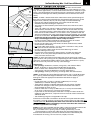
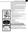
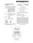
Do It Yourself FLOOR WARMING Heating Wire INSTALLATION MANUAL 888-432-8932 www.suntouch.com/diy Please be aware local codes may require this product and/or the thermostatic control to be installed or connected by an electrician. Please leave this manual with the end user. 2 SunTouch Heating Wire - Do It Yourself Manual SunTouch Heating Wire Installation Facts Heating Wire is a simple, economical way to warm any floor, and provide years of lasting comfort. This instruction manual provides complete details, suggestions, and safety precautions for installing this floor-warming system. Fasten the cables to the floor. Then, depending on the floor coverings to be used, put down a layer of thin-set, thick-set, or self-leveling mortar on top of the cables. Finally, install the floor coverings. It’s that simple! Time to install An average size bathroom should take about two hours to install the cables and about four hours to install the electrical box, control, and power supply. Table of Contents Phase 1: Design the System . . . . . . . . . . . . . . . . . . . . . . . . . . . . . . . . . . 3 Phase 2: Preparation . . . . . . . . . . . . . . . . . . . . . . . . . . . . . . . . . . . . . . . . . 4 Cautions . . . . . . . . . . . . . . . . . . . . . . . . . . . . . . . . . . . . . . . . . . . . . . . . . 4 Tips . . . . . . . . . . . . . . . . . . . . . . . . . . . . . . . . . . . . . . . . . . . . . . . . . . . . . . 5 Items Needed . . . . . . . . . . . . . . . . . . . . . . . . . . . . . . . . . . . . . . . . . . . . 5 Phase 3: Inspect the Cable and Sensor . . . . . . . . . . . . . . . . . . . . . . 5 Cable and Sensor Resistance Log . . . . . . . . . . . . . . . . . . . . . . . . . 6 Phase 4: Electrical Rough-in . . . . . . . . . . . . . . . . . . . . . . . . . . . . . . . . . 7 New Construction . . . . . . . . . . . . . . . . . . . . . . . . . . . . . . . . . . . . . . . . 7 Existing Construction . . . . . . . . . . . . . . . . . . . . . . . . . . . . . . . . . . . . 7 Phase 5: Install the Cable . . . . . . . . . . . . . . . . . . . . . . . . . . . . . . . . . . . . 8 Getting Started . . . . . . . . . . . . . . . . . . . . . . . . . . . . . . . . . . . . . . . . . . 8 General Installation . . . . . . . . . . . . . . . . . . . . . . . . . . . . . . . . . . . . . . 9 Other Installations . . . . . . . . . . . . . . . . . . . . . . . . . . . . . . . . . . . . . . 10 Final Steps . . . . . . . . . . . . . . . . . . . . . . . . . . . . . . . . . . . . . . . . . . . . . . 11 Phase 6: Finish Wiring . . . . . . . . . . . . . . . . . . . . . . . . . . . . . . . . . . . . . . 12 New Construction . . . . . . . . . . . . . . . . . . . . . . . . . . . . . . . . . . . . . . . 12 Existing Construction . . . . . . . . . . . . . . . . . . . . . . . . . . . . . . . . . . . 12 Phase 7: Install the Control . . . . . . . . . . . . . . . . . . . . . . . . . . . . . . . . 13 Phase 8: Install the Floor Coverings . . . . . . . . . . . . . . . . . . . . . . . 13 Phase 9: Install Insulation . . . . . . . . . . . . . . . . . . . . . . . . . . . . . . . . . . 13 Phase 10: System Operation . . . . . . . . . . . . . . . . . . . . . . . . . . . . . . . 13 Troubleshooting Guide . . . . . . . . . . . . . . . . . . . . . . . . . . . . . . . . . . . . 14 Appendix 1: Types of Construction . . . . . . . . . . . . . . . . . . . . . . 15 Appendix 2: Typical Electrical Wiring Diagrams . . . . . . . . . 17 Appendix 3: Connecting Multiple Cables . . . . . . . . . . . . . . . . 19 Appendix 4: Connecting the LoudMouth™ . . . . . . . . . . . . . . . 20 Appendix 5: Sample Layouts . . . . . . . . . . . . . . . . . . . . . . . . . . . . . 21 Skill level This product may be secured in place by an average do-it-yourself person or qualified installer. However, electrical wiring is required from a circuit breaker or other electrical circuit to the control, so it is recommended that an electrician perform these installation steps. Please be aware that local codes may require this product and/or the control to be installed by an electrician. Prior to installation you are required to consult your local codes in order to understand what is acceptable in your area. To the extent this information is not consistent with local codes, the local codes should be followed. Expected floor temperature The floor temperature attainable is dependent on how well the floor is insulated, the temperature of the floor before start up, and in the case of uninsulated slab applications, the thermal drain of the underlying materials. These are the three most common installations: 1. Wood subfloor: With the cable installed on a well-insulated wood subfloor, and thinset mortar and tile on top, most floors can be heated up to 20°F (11°C) warmer than they would otherwise be. 2. Insulated concrete slab: With the cables installed on an insulated concrete slab, and thin-set mortar and tile on top, most floors can be heated up to 15°F (8.3°C) warmer than they would otherwise be. 3. Uninsulated concrete slab: With the cables installed on an uninsulated concrete slab, and thin-set mortar and tile on top, most floors can be heated up to 10°–15°F (5.6 to 8.3°C) warmer than they would otherwise be. Please consult a designer or the factory if questions remain about the surface temperature that can be expected from the cables in any particular construction. Please see “Phase 9”: Install Insulation” on page 13. Specifications: SunTouch Heating Wire is a complete heating cable consisting of a series resistance heating cable and single power lead for easy single-point connection. The heating cable cannot be cut to fit. Voltages: 120, 240 VAC, 1-phase Watts: 10.3 W/sqft (35 Btu/h/sqft) when spaced 3.5 inches on center, up to 14.4 W/sqft (49 Btu/h/sqft) when spaced 2.5 inches on center. (see Table 1) Maximum heater current: 11 amps Maximum circuit load: 16 amps Maximum circuit protection: 20 amps breaker GFCI: (Ground Fault Circuit Protection) required for each circuit (included in the SunStat control) Listing: UL Listed for U.S. and Canada under UL 1673 and CAN/CSA C22.2 No. 130-03, File No. E185866 Application: (-X) - (see UL Label on product) For indoor floor heating application only (-W) - (see UL Label on product) Wet Rated for use in wet locations per this manual Embedded in polymer-modified cement based mortar (see Appendix 1) Minimum bend radius: 1 inch Maximum exposure temperature: (continuous and storage) 194ºF (90ºC) Minimum installation temperature: 50ºF (10ºC) SunTouch Heating Wire - Do It Yourself Manual STEP 1.1 3” spacing NEVER use less than 2.5” spacing. 3 Phase 1: Design the System Heating Wire should be installed in all interior floor areas that are to be warmed. It cannot be used for exterior applications, snow melting, or in ceilings. In some applications, it can be used to heat the room as well, but in general it is not designed for this purpose (heat-loss calculations must be made to determine if enough heat will be provided to match the heat loss of the room). STEP 1.1 Make a sketch of the room. Measure the total square footage of floor area to be warmed (measurements should be made all the way to the edge of walls, cabinets, tub, etc., for now). Keep in mind the following: • Heat will not radiate beyond about 2” on either side of the cable, therefore consistent coverage is important. • The cables can be installed in permanent bench seats with tile or stone coverings. • Type (-W) cables only (see UL Label on product) may be installed into shower floors and bench seats. However, do not install them into the walls. Consider installing a dedicated cable in the shower area separate from the rest of the bath floor. In case there is ever a problem with the shower installation, this cable could be disconnected without loss of heat to the rest of the floor. Acceptance of this shower application must be verified by the local inspector or authority having jurisdiction. See Step 5.20 and Appendix 5 for details and precautions. • Do not install the cables underneath cabinets or fixtures or inside a wall. Excessive heat will build up and cause damage. • Do not run the cables into small closets or other confined areas where excessive heat will build up. • Do install cable within about 1-1/2” to 2” from a counter or vanity in the kick-space to ensure warmth in this area. • Do not install the cables closer than 6” from toilet rings to avoid possible melting of wax rings. • In open areas, like sunrooms or dining rooms, consider installing the cables 6” to 12” away from the perimeter of the room since people rarely stand this close to walls. STEP 1.2 Select the cable spacing. Below are typical spacings for various types of rooms. This spacing can vary depending on the insulation of the floor and room, and the desired effect. Never space cables closer than 2.5” apart; this will cause a very hot area and may cause damage. 4” spacing 3.5” spacing NEVER exceed 3.5” spacing. Typical uses: • 2.5” spacing: Bathrooms, kitchens, living areas, and sunroom floors. (NOTE: Insulation is always recommended due to high heat losses in these areas. Performance is never guaranteed due to construction and climate differences in these applications.) • 3.5” spacing: Hallways, entryways, and large areas with low heat loss. STEP 1.3 Multiply the square footage measured in Step 1.1 by 0.90 to allow for 3” spacing around the edges of the floor area. Use this resulting square footage to select the appropriate cable from the tables on page 4. Remember: • Do not place over 15 amps at 120 VAC (1800 watts) or 15 amps (3600 watts) at 240 VAC through a control. • Select either 120 VAC or 240 VAC depending on the power available. DO NOT mix voltages on the same system if more than one cable is to be installed to cover an area. • Load no more than 12 amps (1440 watts) on a 15-amp circuit breaker, or 16 amps (1920 watts) on a 20-amp circuit breaker. • If you have an area that requires more than 15 amps of cables to be controlled by one thermostat, a separate SunStat must be used to control the additional load. • See the Wiring Diagrams in Appendix 2 for help. If the exact size of cable calculated is not found in the spool selection tables on page 4, it may be necessary to adjust the warming area(s) or select the next smaller spool size. Remember, the cable must never be cut shorter to fit, and must be embedded completely in mortar in the floor. Be careful not to select a spool that is too large. STEP 1.4 The strap supplied with the cable is used to secure the cable to the floor. One box contains 25 ft. of strap, enough to prepare about 50 sq. ft. of floor at 4-ft. spacing. Strap is usually spaced every 3 to 4 ft. Use of methods to secure the cable other than those described in this Manual voids the Warranty and are not allowed unless authorized by the manufacturer in writing. Do not use nails, staples, or similar. 4 SunTouch Heating Wire - Do It Yourself Manual Table 1: 120 VAC Heating Wire Kits* Model Number CO120020R CO120030R CO120040R CO120050R CO120060R CO120070R Total sq. ft Total sq. ft Total sq. ft 2.5” Spacing 3” Spacing 3.5” Spacing Length Amp. Resistance 14.4 watts/sq. ft. 12 watts/sq. ft. 10.3 watts/sq. ft. (ft) Draw (ohms) 17 25 33 41 50 58 20 30 40 50 60 70 23 35 47 58 70 82 78 117 156 195 234 273 2 3 4 5 6 7 64-79 37-46 27-35 21-26 20-26 16-21 47 70 94 117 140 164 156 234 312 390 468 546 2 3 4 5 6 7 128-157 74-91 55-69 41-52 40-51 33-41 * Kits include cable strap, double sided tape, and manual Table 2: 240 VAC Heating Wire Kits* CO240040R CO240060R CO240080R CO240100R CO240120R CO240140R 33 50 66 83 100 116 40 60 80 100 120 140 * Kits include cable strap, double sided tape, and manual NO! Phase 2: Preparation CAUTION! As with any electrical product, care should be taken to guard against the potential risks of fire, electric shock, and injury to persons. The following cautions must be observed: NEVER bang a trowel or other tool on the heating cable. ALWAYS! Always completely embed the factory splice and all heating wire in mortar. NEVER bend the splice or place any part of it in the wall or through the floor. NO! NEVER use less than 2.5” spacing. ALWAYS NEVER cut the heating cable. The 10-ft. power lead may be cut shorter if necessary, but never removed from the heating cable. NEVER use nails, staples, or similar to fasten the heating cable to the floor. NEVER bang a trowel or other tool on the cable. Be careful not to nick, cut, or pinch the cable causing it to be damaged. NEVER install the cables under cabinets or other built-ins. Excessive heat will build up under these items and cause damage. NEVER install the cable in any walls, over walls or partitions that extend to the ceiling, or in closets. NEVER extend the heating portion of the cable beyond the room or area in which it originates. NEVER attempt to repair a damaged cable. Contact the factory for assistance. NEVER overlap heating cables. Dangerous overheating can occur. NEVER allow a power lead or sensor wire to cross a heating cable; damage could result. NEVER embed the cables in adhesives intended for laminate or vinyl flooring. Cables must be completely embedded in cement-based polymer-modified mortar. NEVER apply the wrong voltage to a cable. Damage can result. NEVER use less than 2.5” spacing. ALWAYS completely embed the heating wire and factory splice in mortar. ALWAYS maintain a minimum of 2.5” spacing between cables. ALWAYS use copper only as supply conductors to the control and the cable. Do not use aluminum. ALWAYS test the cable resistances and record them in the Cable and Sensor Resistance Log (page 6). ALWAYS pay close attention to voltage and amperage requirements of the circuit breaker, control, and the cable system. For instance, do not supply 240 VAC to 120 VAC controls and cables. ALWAYS make sure all electrical work is done in accordance with local building codes, the National Electrical Code (NEC), especially Article 424, Part IX, and Section 62 of the Canadian Electrical Code (CEC) Part I. SunTouch Heating Wire - Do It Yourself Manual 5 Some Tips Trowel. Use a plastic trowel to reduce the possibility of cable damage. Insulation. The better insulation that is provided, the more efficiently the system operates, and the better the floor is heated. Concrete slab surfaces offer the most thermal drain and should be insulated before applying the cables, if at all possible. See “Phase 9: Install Insulation” as well as the cross sections in Appendix 1. Controls. The SunStat control will provide direct floor-warming control for better comfort. Mortars. Self-leveling mortars are becoming more popular to use because of their ease of application over the cables. If laying tile, another layer of thin-set will need to be applied in order to lay the tile. Always use polymer-modified cement-based mortar. Do not use solvent-based adhesives or pre-mixes because they are not as heat resistant. LoudMouth™ (sold separately) The LoudMouth sounds an alarm if damage occurs to the cable during installation. The LoudMouth stays connected to the power leads throughout cable and tile installation. Items Needed STEP 3.1 SunTouch Heating Wire, Cable Strap, and control all available from retailer. Other items may be obtained at a local hardware store. Materials: • SunTouch Heating Wire system • Cable Strap • SunStat control with floor sensor • 20-amp circuit breaker (single for 120-VAC and dual for 240-VAC systems) • Electrical box (extra deep) for the control; single-gang (not a gangable type) or 4”-square deep box with a single-gang “mud ring” cover • 4” junction box with a cover, if needed • Cable clamps for junction box (for new construction) • Flexible or rigid conduit (for new construction) • 12-gauge or 14-gauge electrical wiring cable (consult local code) • Wire nuts if using a junction box • Nail plate • Polymer-modified cement based mortar Tools: • Digital multi-meter [for ohms testing; must read up to 20,000 ohms (Ω) to measure sensor] • Drill with 1/2” bit • Hammer and chisel • Wire strippers • Phillips screwdriver • Fish tape (for existing construction) • Hole saw (for existing construction) • Trowel (plastic preferred) with 3/8” notches (or greater) Phase 3: Inspect the Cable and Sensor STEP 3.2 STEP 3.1 Take the cable out of the box and inspect it to make sure there is no visible damage. There are shielded leads coming out of the spool of cable called the “power leads” (they are simply power supply cables that do not heat). The power leads are approximately 10 ft. long and will connect the heating cable to the control for power. STEP 3.2 Record the product information. There is a factory-applied nameplate label on the power leads. Do not remove this label. Record the cable serial number, model number, voltage, and cable resistance range in the Cable and Sensor Resistance Log (page 6). If installing more than one cable, do this for each of them. 6 SunTouch Heating Wire - Do It Yourself Manual IMPORTANT! To retain the Limited Warranty, the following measurements must be recorded, and all steps of this manual followed. STEP 3.3 Take resistance readings of the cable and floor sensor to make sure they are not damaged. It is very important that this be done throughout the entire installation process. Use a quality digital ohmmeter or multimeter [able to measure up to 20,000 ohms (Ω)] to make these measurements. Analog meters (that use a moving needle) are not accurate for this product and should not be used. Take resistance readings (1) before beginning the installation, (2) after the cable and sensor are fastened to the floor, and (3) after floor coverings are installed. Checking these measurements frequently during finished floor installation is strongly recommended in order to avoid burying a damaged cable. STEP 3.3 Floor Sensor Resistance Values Temperature Typical Values 55°F (13°C) 17,000 ohms 65°F (18°C) 13,000 ohms 75°F (24°C) 10,000 ohms 85°F (29°C) 8,000 ohms Check for Breaks Measure resistance between the black and white cable leads (black and blue leads for 240-VAC cables) and record this in the chart below. This measurement should be within the cable resistance range shown on the nameplate label. Measure between the lead wires of the floor sensor. This resistance varies according to the temperature sensed in the tip. The sensor resistance table at left provides approximate values for comparison. A cut or break in the wire is indicated by a resistance of “infinite” ohms (no continuity). Check for Short-Circuits Measure resistance between the black and ground leads and between the white and ground leads (blue and ground leads for 240-VAC cables) and record this value below. These measurements should be “infinite” ohms (no continuity). A cut or pinch in the wire is typically indicated by a resistance value less than the cable resistance range. Cable and Sensor Resistance Log CABLE 1 Cable serial number Cable model Cable voltage Factory cable resistance range OUT OF THE BOX BEFORE INSTALLATION (ohms) Cable black to white (black to blue for 240VAC) Cable black to ground Cable white to ground (blue to ground for 240VAC) Sensor wire AFTER CABLE AND SENSOR ARE FASTENED TO FLOOR (ohms) Cable black to white (black to blue for 240VAC) Cable black to ground Cable white to ground (blue to ground for 240VAC) Sensor wire AFTER FLOOR COVERINGS ARE INSTALLED (ohms) Cable black to white (black to blue for 240VAC) Cable black to ground Cable white to ground (blue to ground for 240VAC) Sensor wire RETAIN THIS LOG TO RETAIN THE WARRANTY! DO NOT DISCARD! CABLE 2 CABLE 3 SunTouch Heating Wire - Do It Yourself Manual STEP 4.2 7 Phase 4: Electrical Rough-in See wiring diagrams in Appendix 2 for different voltages and applications. For additional help, call 800-363-1501. New Construction (see below for existing construction) OVERVIEW We recommend the floor-warming system be installed on a dedicated circuit coming directly from the circuit breaker panel. Follow all National Electric Code (NEC), Canadian Electrical Code (CEC), and other local electrical code requirements when installing this system. Work should be done with great care and with the power turned off to the circuit being worked on. STEP 4.1 Install a maximum 20-amp circuit breaker(s) into the breaker panel, depending on the load of the system. Use a 120-VAC single-pole breaker for a 120-VAC system. Use a 240-VAC double-pole breaker for a 240-VAC system. Install an extra-deep single-gang box if connecting one or two cables to the control. Use a 4”-square deep box with a single-gang mud ring cover if connecting three cables, because the extra room is needed for the wire, wire nuts, and control. STEP 4.2 Install an electrical box for the control. If installing one to two cables, use an extra-deep single-gang box to allow plenty of room for the wiring. Use a 4”-square box if installing three cables. The box can be located almost anywhere that is well ventilated. However, the best place is in the same room as the cable, typically about 60” above the floor, and within reach of the power lead wires of the cable. If installing more than three cables, it will be necessary to connect their power leads in a junction box first (see Step 4.4) to keep from overfilling the control electrical box. Then route one power supply from this junction box to the control box. STEP 4.3 Following code, feed 14- or 12-gauge NM type electrical wiring from the circuit breaker panel to the control electrical box. Leave about 6”–8” of extra wire extended from the box to work with. STEP 4.4 If the control box must be mounted in a location that is too far to reach with the power lead wires, it will be necessary to mount a junction box where the lead wires can be terminated. Use a standard junction box with a cover, mounting it below the floor, in the attic, or in another easily accessible location. It must remain easily accessible and not located behind a wall, cabinet, or similar obstruction. Then use 14- or 12-gauge NM type or other accepted electrical wiring to connect from the junction box to the control box. STEP 4.5 Drill two 1/2” holes in the baseplate directly below the control electrical box. Then, as close to the floor surface as possible, drill two horizontal holes, intersecting the top holes. STEP 4.5 STEP 4.6 If conduit is required by local electrical code, cut a length of 1/2” to 3/4” electrical conduit to run from the control box down to the baseplate. At the baseplate it may be necessary to chisel out more of the wood to make it easier to feed the wires up through the conduit. STEP 4.7 Mark the circuit breaker in the panel which feeds the system with “Floor warming/bath” or similar description. Existing Construction OVERVIEW It is recommended that the system be installed on a separate, dedicated circuit coming directly from the breaker panel. In existing construction, however, it may be difficult to do this depending on the location of wiring and the breaker panel. Tapping off an existing circuit may be possible, but only if there is enough load capacity to handle both the system and any additional loads that may be placed on the circuit. Keep in mind that typical hair dryers can pull up to 10 amps (1200 watts) of load. Follow all NEC, CEC, and other local electrical code requirements when installing this system. Work should be done with great care and with the power turned off to the circuit being worked on. 8 SunTouch Heating Wire - Do It Yourself Manual STEP 4.9 STEP 4.8 Install a maximum 20-amp circuit breaker(s) into the breaker panel, depending on the load of the system. Use a 120-VAC single-pole breaker for a 120-VAC system. Use a 240-VAC double-pole breaker for a 240-VAC system. STEP 4.9 Cut an opening in the wall for the control electrical box. If installing one to two cables, use an extra-deep single-gang box to allow plenty of room for the wiring. Use a 4”-square box if installing three cables. The box can be located almost anywhere that is well ventilated. However, the best place is in the same room as the cable, typically about 60” above the floor, and within reach of the power lead wires of the cable. If installing more than three cables, it will be necessary to connect their power leads in a junction box first (see Step 4.11) to keep from overfilling the control box. Then route one power supply from this junction box to the control box. STEP 4.10 STEP 4.10 Following code, feed 14- or 12-gauge NM type electrical wiring from the circuit breaker panel to the control electrical box opening. Leave about 6”–8” of extra wire extended from the opening. STEP 4.11 If the control box must be mounted in a location that is too far to reach with the power lead wires, it will also be necessary to mount a junction box where the lead wires can terminate. Use a standard junction box with a cover, mounting it below the floor, in the attic, or in another easily accessible location. It must remain easily accessible and not located behind a cabinet or similar obstruction. Then use 14- or 12-gauge NM type or other accepted electrical wiring to connect from the junction box to the control electrical box. STEP 4.12 At the floor level below the control box, cut a 2”x 2”-wide piece from the wall surface. Use a wood chisel to notch out a channel in the baseplate to make it easier to route the wires up the wall. STEP 4.13 Mark the circuit breaker in the panel which feeds the system with “Floor warming/bath” or similar. Phase 5: Install the Cables STEP 4.11 Getting Started IMPORTANT! Refer to Phase 8 and Appendix 1 to make sure the floor is properly prepared for installation of the cable(s), especially the use of reinforcement, leveling, and insulation on concrete slab. STEP 5.1 Use the sketch and design considerations made earlier in Phase 1 to begin laying the cables. Do not install the cables closer than about 6” from wax toilet rings and plumbing to keep from overheating these items. STEP 4.12 STEP 5.2 Make sure to space the cables to provide the warmth desired. WARNING: This heating cable CANNOT be cut shorter to fit! Do not overlap or cross over heating cable on itself. Do not space heating cables less than 2.5” apart. Failure to do so may result in damage to the product and dangerous overheating. STEP 5.3 If this is new construction, draw lines on the floor or use templates to outline the area of any cabinets, fixtures, or future walls that will be placed in the room. NEVER install the cables under cabinets, fixtures, or walls. Excess heat may build up under these items and cause damage. STEP 5.3 STEP 5.4 Decide which direction the cables will run on the floor for the easiest coverage. Refer to the sample layouts in this manual for assistance. Depending on the shape of the area, it may help to think of it in terms of several smaller areas. NEVER use less than 2.5” spacing. SunTouch Heating Wire - Do It Yourself Manual STEP 5.5 General Installation STEP 5.5 Measure about 3” from the wall for the strap. If the design called for 6”–12” away from the wall, install the strap at that distance. In counter or vanity kick-spaces, install the strap so the cable will be 1-1/2” to 2” away from the vanity. STEP 5.6 Cut the strap to fit the length of the first area. STEP 5.7 Secure the strap to the floor using double-sided tape, or using hot glue. STEP 5.6 STEP 5.8 For added securement, on concrete floors, use a hammer drill to set holes into the concrete. Secure the strap every 6”–10” by driving anchors into the holes. STEP 5.9 Cut another piece of strap for the other end of the area and secure 3” from the wall(s) or other obstruction(s). STEP 5.10 Unreel the power leads of the cable up to the factory splice. Let the coil of power leads sit on the floor for now. Beyond the factory splice is the heating cable itself. Factory splice must be installed in the mortar bed. CAUTION: Completely embed the factory splices and heating cable in the mortar, and never bend the factory splices. NEVER allow any part of the splice or heating cable to enter a wall or drop through the subfloor. STEP 5.8 STEP 5.11 Before installing more strap, fill in the first section with cable. Begin by making a “strain-relief” at the beginning so the cable is not accidentally pulled loose. STEP 5.9 STEP 5.10 STEP 5.12 Weave the cable back and forth across the area at the desired spacing until the other side of the room has been reached. Once this area is completed, press down all the tabs. NEVER space the cables less than 2.5” apart. STEP 5.13 If there are additional areas to cover with cable, cut the lengths of strap necessary, attach them to the floor, and begin weaving the cable into that area. STEP 5.11 9 10 SunTouch Heating Wire - Do It Yourself Manual STEP 5.14 Other Installations Because many different room shapes and floor obstructions may be encountered in any given installation, additional layouts are provided below to assist in determining the best way to complete installations in oddshaped areas. STEP 5.15 Corner shower or vanity STEP 5.14 For an angled area, such as a corner shower, first cut several pieces of strap a little longer than the cable spacing being used. STEP 5.16 STEP 5.15 Use a chalk line or pen to mark the floor at 3” from the edge of the shower. STEP 5.16 Use this chalk line to attach each piece of strap to the floor so that the cable does not get any closer to the corner shower than 3”. Make sure that the cables are spaced evenly and parallel to one another. STEP 5.17 STEP 5.17 Fill in the section with cable. Door entryway STEP 5.18 STEP 5.18 For an entryway or other small area where warmth is required, begin by cutting two lengths of strap a little shorter than the length of the entry opening. Then secure the two straps parallel to each other. Bench Seat STEP 5.19 If covering a bench seat or step area (not in a shower area), place a single run up the riser. Use straps to secure the cable to the seat area at the desired spacing, then install a single run down the riser. Again, the cable on the riser and seat area MUST be fully embedded in mortar and have approved floor coverings. Use hot glue where necessary to secure the cable flat against the riser. Shower area installation This application into a shower area must be verified by the local inspector or the authority having jurisdiction. STEP 5.20 Type (-W) cable (see UL Label on product) may be installed into a floor or bench seat located in a shower area. It must never be installed into walls. In general, the cable should be completely embedded into mortar directly below the surface coverings of tile or stone. Other types of coverings are not recommended. See Appendix 5 for an example of this type installation. Alternatively, it may be embedded in mortar beneath the waterproof system, however performance will be reduced. Consider installing a dedicated cable in the shower area separate from the rest of the bath floor. In case there is ever a problem with the shower installation, this cable could be disconnected without loss of heat to the rest of the floor. STEP 5.21 Make sure the power lead factory splice (the connection between the power leads and the heating cable) is located outside the shower area and at least 1’ away from shower openings and other similar areas normally exposed to water. Make sure the control is located at least 4’ away from shower openings such that it cannot be exposed to water or touched by a person in the shower area. STEP 5.22 If the heating cable must enter the shower area over a curb, notch the corners of the curb with a minimum 1” wide notch to ensure the cable is not bent sharply or pinched when surface coverings are installed. Do not damage any waterproofing components, and do not run the heating cable through a non-masonry curb, causing it to overheat. STEP 5.23 If covering a shower floor, cut lengths of strap and secure to the floor with adhesives. Do not use fasteners that penetrate any waterproofing membrane or waterproofing system. Fill in the floor area with SunTouch Heating Wire - Do It Yourself Manual cable. Around the drain leave at least 2” spacing from the edge of the flange. Make sure cable is not placed where door hardware, handrails, or other items may mount to the floor. STEP 5.24 If covering a bench seat in the shower, cut lengths of strap and secure to the top surface of the seat with adhesives. Do not use fasteners that penetrate any waterproofing membrane or waterproofing system. Use hot glue to secure a single run of cable up the side of the bench riser. Fill in the seat area with cable. Then secure a single run of cable down the riser if needed. STEP 5.25 If the cable cannot exit the shower area, the end of the cable has a waterproof splice that may be located in the shower area, fully embedded into the mortar like the heating cable. STEP 5.26 If any part of the heating cable entering a shower area is damaged during installation, do not attempt to repair it. A field repair or modification of the cable may result in serious shock hazard. SunStat Control Factory Splice Thermostat Sensor Wire Strap Thin Set Mortar Tile/Stone SunTouch Heating Wire installed in shower floors and/or benches. See Step 5.20 and Appendix 5. Final Steps STEP 5.27 If a second cable is to be installed in the area, all power leads must come back to the control, or to a junction box and then to the control. NEVER run power leads across heating cables, under baseboard areas, or other potentially damaging areas. Never join two cables in series. STEP 5.28 To secure long lengths of heating cable, place additional, short lengths of the strap at 3 to 4-ft. intervals. Spray the back of the strap with a high-tack adhesive, and slide the strap, upside down, under the cables. Turn the strap over when it is positioned and adhere to the floor. Press the tabs down over the cables. If a spray adhesive was not used, carefully secure these short lengths of strap to the floor without damaging the cable. STEP 5.29 After the cable installation is completed, inspect the work. Make sure all tabs are pressed down, cable spacings are correct, no cables cross over each other, all the cables are undamaged, and all areas to be heated are covered with cable. STEP 5.30 Take resistance readings of the cable again to make sure it has not been damaged during the installation. This is very important to do. Record these readings in the Cable and Sensor Resistance Log (page 6). STEP 5.31 (optional) With the heating portion of the cable fully installed, it is recommended that the cable be temporarily connected to the power source and allowed to heat for several minutes. After the cables begin to feel warm to the touch, disconnect the power. STEP 5.32 Lay cardboard, carpet, or similar material over the cables to protect them from damage until the floor covering is installed. 11 12 SunTouch Heating Wire - Do It Yourself Manual STEP 6.1 Phase 6: Finish Wiring STEP 6.1 Chisel a channel into the floor to lay the factory splice into. This will ensure the splice does not create a high-spot in the floor. CAUTION: The power lead splice MUST BE FULLY EMBEDDED IN the mortar bed and never bend the factory splices. NEVER allow any part of the splice or heating cable to enter a wall or drop through the subfloor. New Construction STEP 6.2 Feed the power leads from the cable up through the hole drilled in the baseplate, or up into the conduit to the control electrical box (or junction box if one was used). STEP 6.3 STEP 6.3 Secure the power lead splice into the chiseled channels with hot-glue. STEP 6.4 Below the control, or wherever the floor sensor is to be located, measure at least 1 ft. into the heated area. Mark the spot where the sensor will be attached to the floor. Be sure to locate the sensor exactly between two of the heating cables. STEP 6.5 To make sure the sensor tip does not create a high spot in the floor, chisel a channel into the floor and lay the sensor tip into the channel. Hot glue the tip into place. STEP 6.5 STEP 6.8 STEP 6.6 Drill another hole into the baseplate, if needed, to feed the sensor wire up to the control box. Finish by securing a steel nail plate over the wires to protect them against baseboard nails later. STEP 6.7 If it was necessary to end a power lead at a junction box, feed 14- or 12-gauge electrical wire from this box to the control box. Tip: If more than one cable was installed, label the ends of the power leads with a brief description as to which area they supply power. Use tape to label them “Cable 1,” “Cable 2,” “Kitchen,” “Bath,” or similar. This will make it easier to identify the leads later on. Take photos of the installation. This will provide a useful record for any future needs. STEP 6.4 STEP 6.6 Existing Construction STEP 6.8 Use a fish tape to pull the power leads up the wall to the control electrical box (or junction box if one was used). STEP 6.9 Secure the power lead factory splice into the chisled channel with hot-glue (see photo for Step 6.3). STEP 6.11 STEP 6.10 Below the control, or wherever the floor sensor is to be located, measure at least 1 ft. into the heated area. Mark the spot where the sensor will be attached to the floor. Be sure to locate the sensor exactly between two of the heating cables (see photo Step 6.4). To make sure the sensor tip does not create a high spot in the floor, chisel a channel into the floor and lay the sensor tip into the channel. Hot glue the tip into place (see photo Step 6.5). STEP 6.11 Use a fish tape to pull the sensor up the wall to the control electrical box, and finish by securing a steel nail plate over the power leads and sensor wires to protect them against baseboard nails. SunTouch Heating Wire - Do It Yourself Manual STEP 6.12 If it was necessary to end a power lead at a junction box, feed 14- or 12-gauge electrical wire from this box to the control box. Tip: If more than one cable was installed, label the power leads with a brief description as to which area they supply power. Use tape to label them “Cable 1,” “Cable 2,” or “Kitchen,” “Bath,” or similar. This will make it easier to identify the leads later on. Take photos of the installation. This will provide a useful record for any future needs. Phase 7: Install the Control STEP 7.1 Read and follow the instructions that come with the SunStat control. STEP 7.3 STEP 7.2 Refer to the wiring diagrams in this manual for different voltages and applications. STEP 7.3 Install the electrical box for the control, if this has not already been done. Connect the power leads from the cable (or the electrical wiring coming from junction boxes) to the “LOAD” side of the control. Connect the incoming power to the “LINE” side of the control. Connect the sensor wires to the sensor terminals on the control. Connect the ground leads from the system to the ground wire from the incoming power. STEP 7.4 Install the control into its electrical box and turn the circuit breaker on to power the system. Test the system and control for several cycles. It should allow the heating cables to heat up correctly. Note: Consider placing a loose tile over the sensor tip to simulate warming the floor and allow the sensor to register this on the control. STEP 7.5 Retain all instruction sheets and warranties. Phase 8: Install the Floor Coverings STEP 8.1 Make a Final Inspection of the Installation. Inspect the installation very carefully for evidence of damage or missing sensor(s). STEP 8.2 Select Type of Construction. Choose the best thin-set, thickset, or self-leveling mortar method for the application. See Appendix 1 regarding final floor installation techniques. Consult with building professionals and/or the factory if assistance is required. STEP 8.3 Take Another Resistance Reading! After floor coverings have been installed, take resistance readings of the cable again to make sure it has not been inadvertently damaged. This is very important to do. Record these readings in the Cable and Sensor Resistance Log (page 6). Phase 9: Install Insulation Insulate under the subfloor for better performance and efficiency of the system. Refer to the Appendix 1 for diagrams and insulation recommendations. Phase 10: System Operation After all system components are in place and floor coverings installed, briefly test the operation of the system but do not put the system into full operation until the mortar materials are fully cured (typically one to four weeks). See the mortar manufacturer’s recommendations for the specific type of mortar used. Many manufacturers of laminate and wood flooring recommend a maximum of about 84°F (29°C) on the floor surface. Be sure to program the control accordingly. Consult the manufacturer regarding recommended floor temperatures for the flooring being installed. Energize the system. Operate the controls so that the system turns on the floor-warming cable. The control will normally indicate that power is being supplied to the cable. It will take some time for the cable to warm up. Using a clamp-type ammeter (electricians normally carry these), pull the control out of the wall and determine whether the cables are pulling current, thus indicating they are working as intended. Turn the system off after NO MORE than 10 minutes of operation. Do not operate the system again until the floor mortar is cured. Once the flooring is completely cured, the control can be used to operate the system for many years to come. STEP 7.4 13 14 SunTouch Heating Wire - Do It Yourself Manual Troubleshooting Guide If not qualified to perform electrical installations, it is strongly recommended that a qualified, licensed electrician be hired to install the heating cables and related electrical components. If problems with the system arise, please consult the troubleshooting guide below. Any troubleshooting work should be done with the power removed from the circuit, unless otherwise indicated. Call 800-363-1501 for further assistance. Problem Possible Cause Solution Cable resistance measurement is outside the range printed on the nameplate label. An analog ohmmeter (using a moving needle) was used to take the reading. Obtain a digital ohmmeter able to read 0 to 20,000 ohms and remeasure the resistance. If measurement shows an open or short circuit, the cable has been damaged. Record resistances between all wires and contact the manufacturer. If measurement is just a little low or high, room temperature has affected the resistance. Make the room temperature 65°–75°F, or contact the manufacturer. The resistance measurement could be from more than one cable wired in series, or wired in parallel. Either will provide false resistance readings. Make sure resistance measurements are for only one cable at a time. When connecting more than one cable to the control, multiple cables must be wired in parallel (i.e., black to black, white to white). The ohmmeter may be set to the wrong scale. For instance, the 200 K ohms scale measures up to 200,000 ohms. The ohmmeter should typically be set to the 200 ohms scale, with the exception of cables having a rating above 200 ohms on their nameplate label. If the resistance reading is outside the range printed on the nameplate label, contact the manufacturer. Cable has been damaged. Measure cable resistance. Check for both “open circuit” and “short circuit” as detailed earlier in this manual. If damaged, record resistances between all wires and contact the manufacturer. GFCI has tripped, indicated by a light on the control or “GFCI TRIP”. Check for loose wire connections. Reset the GFCI on the control or circuit breaker. If it trips again, check for a short circuit in the cable as detailed earlier in this manual. If cable is damaged, record resistances between all wires and contact the manufacturer. If cable is not damaged, replace the GFCI control. Also see “GFCI conflicts” below. Incorrect voltage supplied, or mismatched electrical components used. Measure “line” voltage, 120V cables have black and white leads. 240V cables have black and blue leads. Concrete slab floor. Surface temperatures rise slowly in a slab. If, after 5 to 8 hours of heating, the floor is not warmer to the touch, check for cable damage (see “Cable has been damaged” above). Measure “load” voltage/amperage to cable. Cables are wired in “series” or “daisy chained” (end-to-end). Multiple cables must be connected in “parallel” (or black-to-black, white-to-white). Incorrect wiring. The control was “bypassed” when it was wired to the power supply. Make sure wiring connections are correct. Consult the wiring diagram on the back of the control, the instructions that came with the control, or the wiring diagrams in Appendix 2. Defective control. Return control to dealer for replacement. Floor does not get warm. Floor heats continuously. Floor sensor is not wired properly, or is located Floor temperature shows “HI” or may show tempera- incorrectly. ture over 100°F. Make sure only one floor sensor is connected to the control. Also see “Sensor is loose or broken” above. Control is not working correctly. If a programmable control, the programming may be incorrect. Carefully read and follow control programming instructions. Incorrect voltage supplied, or mismatched components used. Test voltage, verify parts. See “Incorrect voltage supplied” above. Floor sensor is not wired properly, or is not working properly. Make sure only one floor sensor is connected to the control. Also see “Sensor is loose or broken” above. Loose connection(s) on line side and/or load side of control. Remove and reinstall the wire nuts at each connection. Make sure the wire nuts are tight. Check all connections back to the breaker. Defective control. Return control to dealer for replacement. No power is supplied. Check circuit breaker. Measure voltage at the control. Check all connections between breaker and control. Floor sensor is not wired properly, or is not working properly. Make sure only one floor sensor is connected to the control. Also see “Sensor is loose or broken” above. Defective control. Return control to dealer for replacement. More than one GFCI on the circuit. GFCI units sometimes trip when there is nothing wrong with the equipment on the circuit, but when there is more than one GFCI. Reroute power to avoid having more than one GFCI on the circuit. An electric motor or a ballasted light source is sharing the circuit with the cable(s). Electric motors and other electrical devices can cause a GFCI to false-trip. Run a dedicated circuit to the floor-warming system. Control is not working at all. GFCI conflicts and false-trips. SunTouch Heating Wire - Do It Yourself Manual 15 Appendix 1: Types of Construction and Applications The cross sections on these pages depict types of construction (slab vs. frame floor) and applications commonly used in the installation of the cable. Choose the best installation detail for the particular construction and application. Slab Construction and Applications Insulation. In new slab construction, it is highly recommended that foam insulation be installed under and around the slab to prevent loss of radiant heat into the surrounding soil. In existing construction where insulation under the slab is absent, it is strongly recommended that a layer of insulating material be attached to the slab prior to the installation of the cable. Cork, for example, possesses a minimal R value that will help keep the radiant heat at the floor surface. Consult the cork manufacturer regarding proper application and attachment of the cork to the concrete slab. There are other options for insulation as well. Antifracture membrane. While optional, it is recommended that an antifracture membrane be installed directly to the slab or the self-leveling mortar layer underneath the tile. This flexible layer reduces the chance of minor stress and fracturing in the slab from being transmitted upward to the tile. Reinforcement. To further strengthen the floor, consider laying a 1-1/4” to 2” mudbed, reinforced with metal or plastic lath, directly onto the optional antifracture membrane. Then install the cable(s). Framed Floor Construction and Applications In framed-floor construction, the two primary concerns are insulation and floor rigidity. Without proper insulation, radiant heat leaks into the joist spaces. And unless the plywood subfloor is properly reinforced, stresses in the subflooring can cause unsightly cracking in the tile floor. Insulation. The use of insulation in the joist spaces dramatically enhances the performance and efficiency of the floor-warming system. Insulation with an R value of 19 will SLAB Construction and Applications Thin-set mortar over slab (Dry-set or latex cement on slab; TCA #RH115-03) Tile/stone Latex-Portland cement mortar bond coat Heating cable Antifracture membrane or cork underlayment, as needed Slab Insulation beneath slab (per International Residential Code, Chapter 11) Thick-set mortar bed over slab (Cement mortar bonded; TCA #F112-03) Tile/stone or laminate flooring Latex-Portland cement mortar bond coat Heating cable Mortar bed Antifracture membrane or cork underlayment, as needed Slab Insulation beneath slab (per International Residential Code, Chapter 11) Self-leveling mortar over slab on grade Tile/stone or laminate flooring Latex-Portland cement mortar bond coat Heating cable Self-leveling mortar bed Antifracture membrane or cork underlayment, as needed Concrete slab with rewire or rebar Insulation beneath slab (per International Residential Code, Chapter 11) 16 SunTouch Heating Wire - Do It Yourself Manual be sufficient for most regions, while in more temperate areas R-11 will suffice. Do not install rigid insulation layers directly above or below backer board or mortar. If possible, install insulation as shown in the diagrams at right. Reinforcement. There are several options for strengthening the subfloor: 1. Add 3/4”-thick plywood on top of the existing subfloor. 2. Pour a 1/4”–1/2”-thick layer of self-leveling mortar over the existing subfloor, then install the cables on top of the mortar layer. 3. Install a quality cementitious backer board or fiber cement underlayment over the subfloor. Then install the cable and lay the tile. Antifracture membrane. While optional, it is recommended that an antifracture membrane be installed to reduce the chance of minor stress and fracturing in the subflooring from being transmitted upward to the tile. If an antifracture membrane is used, install the cable above the membrane, unless otherwise recommended by the membrane manufacturer. In place of an antifracture membrane, an uncoupling system can be installed to prevent deflection in the subfloor from affecting the tile surface. Mortar Beds FRAMED FLOOR Construction and Applications Thin-set mortar over framed floor (Dry-set or latex cement mortar; TCA #F144-03) Tile/stone Latex-Portland cement mortar bond coat Heating cable Backer board Mortar bed Plywood subfloor Insulation (per International Residential Code, Chapter 11) Joist Thin-set mortar over framed floor (Dry-set or latex cement mortar; TCA #RH130-03) The cables can be installed in three types of mortar beds: thin-set or thick-set mortar beds 3/8” to 1” thick, and self-leveling mortar beds 1/4” to 1/2” thick. Thin-set Mortar Beds. If the cable Thick-set cement mortar with lath will be placed directly onto the slab, (Cement mortar metal lath; TCA #145-03) or if backer board or plywood reinforcement is used on a plywood subfloor, first install the cable then apply the thin-set mortar bond coat directly over the cable and lay the tile. Thick-set Mortar Beds. If a thicker mortar bed is used to strengthen the floor, the cable can be installed under either the mortar bed (also known as “dry-set”) or under the mortar bond coat directly below the tile or stone. In a thick-set application, the cable is generally installed above the mortar bed, but before the thinset bond coat. Thick mortar beds of this type require the use of a reinforcing mesh or lath. Tile/stone Latex-Portland cement mortar bond coat Heating cable Plywood Plywood subfloor Insulation (per International Residential Code, Chapter 11) Joist Tile/stone Latex-Portland cement mortar bond coat Heating cable Mortar bed Metal or plastic lath Plywood subfloor Insulation (per International Residential Code, Chapter 11) Joist SunTouch Heating Wire - Do It Yourself Manual 17 If plastic lath is used instead of the typical metal lath, the cable can be installed before pouring the self-leveling mortar bed. CAUTION: If metal lath is used in the mortar bed, do not allow the cable to come in direct contact with the lath. Damage to the cable could result. Self-leveling Mortar Beds. Self-leveling mortar beds are appropriate if installing non-masonry floor coverings such as engineered wood, vinyl, laminate, or carpet. Attach the cables to the slab or subfloor, then pour a 1/4”–1/2”-thick layer of self-leveling mortar over the cables according to manufacturer’s specifications. Install the floor coverings after the mortar has cured. Regardless of the type of mortar bed used in any particular application, always secure the cable to the floor first, then cover it with the mortar or cement. Never attempt to lay or work the cable into a previously-poured layer of wet mortar. Surface Coverings It is strongly recommended that tile and stone flooring be installed according to manufacturer’s recommendations, Tile Council of North America (TCNA) guidelines, and ANSI specifications. Follow industry and manufacturer’s recommendations when installing non-masonry floor coverings, such as hardwood, vinyl, laminate, or floating floors. For best performance, minimize the insulating value of the coverings selected. Thicker carpets or pads will reduce the heat available on the surface and lose heat below. A total R-value for all surface materials of R-3 is the maximum recommended (most underlayment/wood and pad/carpet combinations are acceptable). Never exceed R-11 total. Other Considerations Expansion joints. In slab or mortar applications, do not install the cables through an expansion joint unless Ground an appropriate antifracture membrane is installed per TCNA recommendations. If not using an antifracture mem120/240 brane, install the cables right up to the joint, if necessary, but not through theVAC joint. SunStat Control mortar bed as shown in the Mosaic tile. When laying mosaic tile, first embed the cables in the appropriate Load 1 Ground diagrams on the previous pages, and allow to cure per manufacturer’s instructions. Then thin-set the mosaic tile Black 120/240 VAC according to typical practice. 120 VAC or SunStat Control Line 1 (max Load 1 Black REMEMBER: If in doubt about anyBlack aspect or phase of the installation, consult with building professionals Black Sensor Wire 120 VAC or 240 VAC Heating Cable and/or the manufacturer regarding installation details before (no polarity) 1 specific 120Line VAC or 240 VAC (maximum 15 amps) Black Black Sensor Wire beginning. 120 VAC or 240 VAC Line 2 White White (no polarity) Load 2 White Load 2 Line 2 Appendix 2: Typical Electrical Wiring Diagrams (120 and 240 VAC) White White White Typical Electrical Wiring Diagram with SunStat Control (120/240VAC) Dedicated 120 or 240VAC, 20-amp (maximum) circuit. Ground 120/240 VAC SunStat Control Load 1 Black CAUTION: Make sure 120 VAC is supplied to 120VAC cables and Sensor Wire 240VAC is supplied to 240VAC(no polarity) cables. Otherwise, dangerous overheating Load 2 and possible fire Whitecan result. hazard Line 1 Black Black 120 VAC or 240 VAC White Line 2 White 120 VAC or 240 VAC Heating Cable (maximum 15 amps) CAUTION: Make sure 120 VAC is supplied to 120VAC cables and 240VAC is supplied to 240VAC cables. Otherwise, dangerous overheating and possible fire hazard can result. Typical Electrical Wiring Diagram with SunStat Control (120/240VAC) Dedicated 120 or 240VAC, 20-amp (maximum) circuit. Ground CAUTION: Make sure 120 VAC is supplied to 120VAC cables and 120/240 VAC SunStat 240VAC Control is supplied to 240VAC cables. Otherwise, dangerous Load 1 overheating and possible fire Black hazard can result. Line 1 Black Black 120 VAC or 240 VAC White Sensor Wire (no polarity) Ground Load 2 White Line 2 White Two or more120 VAC or 240 VAC Heating Cables (maximum 15 amps) 120/240 VAC SunStat Control Load 1 Black Ground Black 120/240 VAC electrician in SunStat Control Line 1 Black Sensor Wire All electrical work must be done by a qualified licensed accordance with local building and electrical codes, the (noand polarity) 120 VAC or 240 VAC National Electrical Code (NEC), especially Article 424, Part IX of the Load 1 NEC, ANSI/NFPA70 and Section 62 of CEC Part 1. White Line 1 Black Line 2 White Load 2 White 18 SunTouch Heating Wire - Do It Yourself Manual Appendix 3: Connecting Multiple Cables NOTE: The control is not shown in these diagrams in order to simplify them. These diagrams are given only as examples of how to properly connect multiple cables. Care must be taken not to overfill a box. Be sure to use wire nuts that are the correct size for the connections being made. Follow all codes for wiring. If in doubt, consult an electrician. Illustration showing how to connect three cables at the control electrical box. Illustration showing how to connect multiple cables from multiple junction boxes at one control electrical box. SunTouch Heating Wire - Do It Yourself Manual Appendix 4: Connecting the LoudMouth Monitor Illustrations showing (left) how to connect the LoudMouth monitor to two cables, and (right) how to connect the LoudMouth to three cables. The LoudMouth can monitor no more than three cables simultaneously. Do NOT leave the power leads connected in “series” like this when making final wiring connections; the cables will not heat sufficiently. 19 20 SunTouch Heating Wire - Do It Yourself Manual Appendix 5: Sample Layouts Master Bathroom (normal heat loss, framed floor construction) Two zones, 120 volts: Bathroom/Zone 1a = 1 spool; 60 sq. ft., 3” spacing. Bathroom (shower) /Zone 1b = 1 spool; 20 sq. ft., 3” spacing. Shower Zone 1b Bath Tub Spool Termination Shower Curb Strap Zone 1a Floor Sensor Vanity Toilet Control IMPORTANT: Example of Type (-W) Cable (see UL Label on product), where cable is installed in a shower area and enters over the curb. See Step 5.20 for complete details and Cautions. This application into a shower area must be verified by the local inspector or the authority having jurisdiction. Detail of Shower Curb Tile Thinset Mortar Shower Curb Heating Wire Notches in Shower Curb (Minimum 1” wide, to avoid sharp bends in cable and ensure cable is fully embedded in mortar.) Factory Splice SunTouch Heating Wire - Do It Yourself Manual Basement Bathroom (high heat loss, below grade basement slab) One zone, 120 volts: 1 spool; 58 sq. ft.; 2.5” spacing. 39 ft. of strap, or two 25-ft. rolls. 1 spool 58 sq. ft. 2.5” spacing Closet Vanity Control Vanity Floor Sensor Spool termination Strap Shower Bath Tub Master Bathroom (normal heat loss, framed floor construction) One zone, 120 volts: 1 spool, 20 sq. ft., 3” spacing. 11 ft. of strap, or one 25-ft. roll. Install cables at least 4”–6” away from toilet rings Spool termination Toilet Closet Vanity Bath Tub 1 spool 20 sq. ft. 3” spacing Strap Floor Sensor Control Layouts continued on next page 21 22 SunTouch Heating Wire - Do It Yourself Manual Master Bathroom (normal heat loss, framed floor construction) One zone, 240 volts: 1 spool; 100 sq. ft.; 3” spacing. 35 ft. of strap, or two 25-ft. rolls. Toilet Install cables at least 4”–6” away from toilet rings Bath Tub Strap Master Bathroom (normal heat loss, framed floor construction) One zone, 240 volts: 1 spool; 80 sq. ft.; 3” spacing. 24 ft. of strap, or one 25-ft. roll. Spool termination Control Vanity Floor Sensor Toilet Vanity Strap Shower 1 spool 100 sq. ft. 3” spacing Install cables at least 4”–6” away from toilet rings Bath Tub Floor Sensor 1 spool 80 sq. ft. 3” spacing Closet Dual Vanity Control Floor Sensor 1 spool 100 sq. ft. 3” spacing ity n Va Va n ity Master Bathroom (normal heat loss, framed floor construction) One zone, 240 volts: 1 spool; 100 sq. ft.; 3” spacing. 50 ft. of strap, or two 25-ft. rolls. Strap Shower Toilet Install cables at least 4”–6” away from toilet rings Closet Spool termination Bath Tub SunTouch Heating Wire - Do It Yourself Manual 23 Electric Floor-warming Products 25-year Limited Warranty Watts Radiant (the Company) warrants its electric floor-warming mats and cables (the Product) to be free from defects in materials and workmanship for twenty-five (25) years from the date of manufacture. Thermostats and controls sold by Watts Radiant are warranted, parts and materials, for two (2) years from the date of purchase. The sole remedy for controls is product replacement. This warranty is transferable to subsequent owners. Under this Limited Warranty, Watts Radiant will provide the following: If the Product is determined by Watts Radiant to be defective in materials and workmanship, and has not been damaged as a result of abuse, misapplication or modification, the Company will refund all or part of the manufacturer’s published list price of the Product at the time of purchase in accordance with the following: 100% for the first ten (10) years, then prorated on a diminishing 25-year scale for the remaining warranty period. For example: (1)Product found defective in the 5th year will receive the full manufacturer’s published list price of the Product at the time of purchase; (2)Product found defective in the 15th year, with 10 years remaining in the warranty period, will receive 10/25ths of the manufacturer’s published list price of the Product at the time of purchase. In order to make a claim, you must: (a)Provide the Company with sufficient details relating to the nature of the defect, the installation, the history of operation, and any repairs that may have been made. (b)At the Company’s discretion and at the owner’s expense, ship the Product to the Company or the Company’s local representative or distributor. (c)Provide proof that the Product was installed in accordance with the applicable Product Installation Manual and any special written design or installation guidelines by Watts Radiant for this project. (d)Provide proof that the Product was installed in accordance with the National Electrical Code (NEC) or the Canadian Electrical Code (CEC), and all applicable local building and electrical codes. (e)Provide a retail sales receipt or proof of purchase. The following are not covered by this Limited Warranty: (a)Any incidental or consequential damage, including inconvenience, loss of time or loss of income. (b)Any labor or materials required to repair or replace the Product or control, not authorized in writing by the Company. (c)Any labor or materials required to remove, repair or replace flooring materials. (d)Any freight or delivery costs related to the Product, the control, or any related flooring or electrical products. Watts Radiant assumes no responsibility under this warranty for any damage to the Product caused by any trades people, visitors on the job site, or damage caused as a result of post-installation work. The staff at Watts Radiant is available to answer any questions regarding the proper installation or application of the Product at this toll-free phone number: 800-276-2419. If you are ever in doubt about the correct installation procedure to follow, or if the Product appears to be damaged, you must call us before proceeding with the installation, or proposed repair. WATTS RADIANT DISCLAIMS ANY WARRANTY NOT PROVIDED HEREIN, INCLUDING ANY IMPLIED WARRANTY OF MERCHANTABILITY OR IMPLIED WARRANTY OF FITNESS FOR A PARTICULAR PURPOSE. WATTS RADIANT FURTHER DISCLAIMS ANY RESPONSIBILITY FOR SPECIAL, INDIRECT, SECONDARY, INCIDENTAL, OR CONSEQUENTIAL DAMAGES ARISING FROM OWNERSHIP OR USE OF THIS PRODUCT, INCLUDING INCONVENIENCE OR LOSS OF USE. THERE ARE NO WARRANTIES WHICH EXTEND BEYOND THE FACE OF THIS DOCUMENT. NO AGENT OR REPRESENTATIVE OF WATTS RADIANT HAS ANY AUTHORITY TO EXTEND OR MODIFY THIS WARRANTY UNLESS SUCH EXTENSION OR MODIFI-CATION IS MADE IN WRITING BY A CORPORATE OFFICER. DUE TO DIFFERENCES IN BUILDING AND FLOOR INSULATION, CLIMATE, AND FLOOR COVERINGS, WATTS RADIANT MAKES NO REPRESENTATION THAT THE FLOOR TEMPERATURE WILL ACHIEVE ANY PARTICULAR TEMPERATURE, OR TEMPERATURE RISE. UL® STANDARD LISTING REQUIREMENTS LIMIT THE HEAT OUTPUT OF REGULAR MATS TO 12 WATTS PER SQUARE FOOT, CABLES TO 15 WATTS PER SQUARE FOOT DEPENDING ON CABLE INSTALL SPACING, AND UNDERFLOOR MATS TO 10 WATTS PER SQUARE FOOT, AND AS SUCH, USERS MAY OR MAY NOT BE SATISFIED WITH THE FLOOR WARMTH THAT IS PRODUCED. WATTS RADIANT DOES WARRANT THAT ALL PRODUCTS WILL PRODUCE THE RATED OUTPUT LISTED ON THE PRODUCT NAMEPLATE, WHEN OPERATED AT THE RATED VOLTAGE. Some states do not allow the exclusion or limitation of incidental or consequential damages and some states do not allow limitations on how long implied warranties may last. Therefore, the above limitations or exclusions may not apply to you. This warranty gives you specific legal rights and you may also have other rights, which vary from state to state. SO FAR AS IS CONSISTENT WITH APPLICABLE STATE LAW, ANY IMPLIED WARRANTIES THAT MAY NOT BE DISCLAIMED, INCLUDING IMPLIED WARRANTIES OF MERCHANTABILITY OR FITNESS FOR A PARTICULAR PURPOSE ARE LIMITED IN DURATION TO TWENTY-FIVE YEARS FROM THE DATE OF MANUFACTURE. Terms and Conditions Shipping Discrepancies: Incoming materials should be inventoried for completeness and for possible shipping damage. Any visible damages or shortages must be noted prior to accepting the material. Once the receiving personnel accept the material on their dock, they have relieved the freight company of any responsibility. Any discrepancy concerning type or quantity of material shipped, must be brought to the attention of Watts Radiant within 15 days of the shipping date entered on the packing slip for the order. Return Policy: Watts Radiant items may be returned within 180 days from the date of purchase, if they are not damaged or used. There will be a 25% restock charge applied to items returned due to overstock or customer order error. All returned items must be in new condition. Products, controls or other parts that have a quality defect will be replaced (not credited) at no charge to the customer. If an item is shipped in error, there will be no restocking charge. All items returned, for replacement, credit or repair, must have a Returned Goods Authorization (RGA) number, or they will not be accepted. Please return the product to the original point of purchase. Products older than 180 days are excluded from these terms and conditions and may not be returned. Products that have been damaged, or Products that have been cut, may not be returned. This includes Products that have had mortar or concrete materials applied to them. These Products cannot be repaired and cannot be resold; therefore, we cannot accept them. Effective: APRIL 1, 2006. This warranty applies to all Products purchased after this date. Watts Radiant 4500 E. Progress Place Springfield, MO 65803-8816 800-276-2419 (toll-free phone) 417-864-6108 (phone) 417-864-8161 (fax) www.wattsradiant.com Affiliations: 4500 E. Progress Place Springfield, MO 65803 Ph: 888.432.8932 Fax: 417.831.4067 Web: www.suntouch.com/diy SunTouch, a Watts Radiant product. Watts Radiant, a Watts Water Technologies Company. IOM-DIY-HeatingWire-EN 1140 EDP# 81015671 The SunTouch manufacturing facility’s Quality System is ISO 9001:2008 registered through LRQA. ©2011 Watts Radiant