1
US007626375B2
(12) United States Patent
(10) Patent N0.:
(45) Date of Patent:
Garland et al.
(54)
(56)
SYSTEM AND METHOD FOR CONFIGURING
U.S. PATENT DOCUMENTS
Inventors: Anthony C. Garland, Camano Island,
5,218,290 A *
WA (US); Joseph Victor Ferrante,
Redmond, WA (US); Brian Michael
EP
JP
0 504 514 A
2001311747 A
David Honsinger, Everett, WA (US);
Jeffrey William Meyer, Seattle, WA
* cited by examiner
Subject to any disclaimer, the term of this
patent is extended or adjusted under 35
Primary ExamineriHa Tran T Nguyen
Assistant ExamineriRoberto Velez
U.S.C. 154(b) by 0 days.
(74) Attorney, Agent, or FirmiPerkins Coie LLP
(21) Appl. No.: 11/838,881
(22)
(52)
(58)
Int. Cl.
G01R 1/38
G01R 11/5 7
G01R 15/00
G01R 15/08
G01R 7/00
ABSTRACT
A digital multimeter With a rotary sWitch having a plurality of
positions, each of the positions corresponding to a primary
measurement function to be performed. An LCD displays
secondary functions or modes corresponding to the positions
of the rotary sWitch and values determined by performing one
Prior Publication Data
US 2009/0045800 A1
(51)
(57)
Aug. 14, 2007
(65)
9/1992
ll/2001
EP Search Report; European Application No. 08162447.0-1524;
Applicant: Fluke Corporation; Mailed Nov. 19, 2008; 24 pages.
(73) Assignee: Fluke Corporation, Everett, WA (US)
Filed:
Beckeit et a1. ............ .. 324/115
OTHER PUBLICATIONS
(Us)
Notice:
6/1993
FOREIGN PATENT DOCUMENTS
Capoccia, Seattle, WA (US); Lindsey
Berdan, Seattle, WA (US); Bradey
(*)
Dec. 1, 2009
References Cited
A DISPLAY FOR A DIGITAL MULTIMETER
(75)
US 7,626,375 B2
Feb. 19, 2009
of the measurement functions. The multimeter includes
default functions for each position of the rotary sWitch that
(2006.01)
(2006.01)
(2006.01)
(2006.01)
(2006.01)
US. Cl. .. ................................... ..
may be changed to other functions or modes. When the other
functions or modes are set in a ?rst position, the rotary sWitch
is moved to a second position, and returned to the ?rst posi
tion the multimeter restores the functions and/or modes set
When the rotary sWitch Was previously in the ?rst position.
324/115; 324/141
Field of Classi?cation Search ..................... .. None
See application ?le for complete search history.
100 1
9 Claims, 11 Drawing Sheets
158
162
160
164
144
121
122
123
124
US. Patent
Dec. 1, 2009
Sheet 2 0f 11
200
US 7,626,375 B2
210
Display
Status Bar
Power Source
Soft Keys Area
220
Controllers/Processors
222
Application Processors
230
Memory
Measurement
Funct'ons
232
221
Modes
Measurement Processors
233
Rotary Switches
240
Rotary Switch Input
l
250
Keys/Buttons Input
260
Ecgeocggag?ggil
234
Status Bar
235
Threshold Values
236
Info Button
FIG, 2
US. Patent
Dec. 1, 2009
Sheet 3 0f 11
US 7,626,375 B2
‘100
f’
‘7
mm-
302 """‘\\
1 1 9 8 VAC
J
105 \/"\ Maximum
Average
312
‘111
m
Minimum
I
127.09
304
/3-O—6 310
00:03:11w47 310
119.50%4/
308 31o
/
/QQ;5;;9';// 112
US. Patent
Dec. 1, 2009
Sheet 5 0f 11
US 7,626,375 B2
100
(I
‘"1
03/13/06 Ii»)
1051,»,
26.554 “NBC
Auto Range
50 mVDC
504 \W/“l Lemar)
[I]
505 111
z. /o.ms
[3 REL
[3 Peak
[1 Probe {F1 508E AC+DC
\I
510
US. Patent
100
Dec. 1, 2009
Sheet 6 6f 11
US 7,626,375 B2
US. Patent
Dec. 1, 2009
Sheet 7 0f 11
US 7,626,375 B2
190
702
m
302/\\
/
93/13/06
0C
704
US. Patent
Dec. 1, 2009
Sheet 8 0f 11
1
US 7,626,375 B2
801
Detect new position of
rotary switch
802
No
Yes
803
Retrieve data from memory
for switch position
812
Defauit measurement
function
Change
v
from default
measurement
function?
Default measurement
function
811
805
Change measurement
function away from default
Mode enabled?
Enable mode
v
808
M
Perform measurement
v
Display
FIG. 8
809
Detect rotation in
rotary switch?
US. Patent
Dec. 1, 2009
Sheet 9 0f 11
US 7,626,375 B2
904
M
[7
K)
1, 123.45 VAC
W
W 902
3 l 6 8 1 Crest Factor
Auto Range
400 VAC
121.22 VAC
WWWM
FIG. 9
US. Patent
Dec. 1, 2009
v
Sheet 10 0f 11
US 7,626,375 B2
1002
Detect mode selected
v
3004
Retrieve display
parameters for the selected
mode
Live, actual
New mode selected?
measurement
removed?
Dynamically con?gure
status bar
v
1010
Retrieve threshold value
Threshold value
exceeded?
lnclude lightening bolt
warning
New mode selected?
FIG. 10
US. Patent
Dec. 1, 2009
US 7,626,375 B2
Sheet 11 0f 11
1100
f/
1102
1106
/
l123£svAc @
Measure Volts DC
?olts DC measures the
“direct current” signals (‘D/X
‘1108
n The lightning bolt indicates a
measurement that exceeds the safe amount @1110
for contact with without protection
W Indicates a “zeroing” of the indac.../
“mm
1112
1114
1116
FIG. 11
1118
/
US 7,626,375 B2
1
2
SYSTEM AND METHOD FOR CONFIGURING
A DISPLAY FOR A DIGITAL MULTIMETER
FIG. 5 illustrates an example of a function and mode menu.
FIG. 6 illustrates a screen displaying a value for a measured
temperature.
BACKGROUND
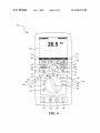
FIG. 7 illustrates a screen that can appear after a user
selects Min/ Max mode by pressing [MIN MAX] button While
Multimeters are used for measuring a variety of parameters
associated With electrical circuitry, such as currents, voltages,
in the screen shoWn in FIG. 6.
resistance and capacitance. A multimeter can be a handheld
device useful for basic fault ?nding and ?eld service Work or
by the multimeter When the rotary sWitch is moved to a neW
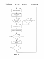
FIG. 8 illustrates a How diagram for the procedure folloWed
position.
a sophisticated bench instrument that can measure With a very
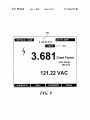
FIG. 9 illustrates a screen in Which a “mini-measurement”
high degree of accuracy. The instrument may be implemented
informs the user of the live reading While display is froZen
With an analog meter de?ected by an electromagnet or With a
With a past reading on hold.
digital display such as an LCD (liquid crystal display) screen.
While older analog multimeters might have basic accuracies
FIG. 10 illustrates a How diagram for dynamically gener
ating the status bar display in accordance With an exemplary
embodiment.
of 5-l0%, modern portable digital multimeters, or DMMs,
may have accuracies up to :0.025%.
FIG. 11 illustrates an example of an information glossary
Multimeters commonly include rotary sWitches con?gured
con?gured for display on an LCD screen on a digital multi
such that each rotated position of the rotary sWitch indicates
a different measuring function. For example, a rotary sWitch
on a conventional multimeter may be con?gured such that a
meter in accordance With an exemplary embodiment.
20
DETAILED DESCRIPTION
?rst position corresponds to a voltage measurement, a second
position corresponds to a current measurement, and a third
position corresponds to a resistance measurement. In this
manner, a single instrument can act as a voltmeter, an amme
ter, or an ohmmeter by simply rotating a sWitch.
Since modern digital multimeters provide far more func
25
tionality than just three measurement types, rotary sWitch
interfaces have been devised such that a single rotary sWitch
position can be to ggled betWeen several measuring functions.
As examples, a single position of a rotary sWitch may corre
spond to different units of measurement, such as Amps (“A”)
integrated, programmable and con?gurable features not
available on conventional multimeters. Several of these fea
30
or milliamps (“mA”), or even different measurement types
altogether, such as a current measurement or a temperature
measurement. Typically, the multimeter provides capability
on the sWitch itself or on a function key to toggle betWeen the
35
different measurement functions Within the single rotary
sWitch position.
40
loWest detected measurement values. As another example, a
user can select to “Record” a measurement value for memory
45
A face for an exemplary multimeter 100 is illustrated in
FIG. 1. In the exemplary embodiment, the multimeter can be
housed With a compact, handheld body, including contour
indentations so as to improve suitability for one-handed
operation. The face of multimeter 100 is generally character
iZed by a display area 105, a rotary sWitch 120, soft keys
110-113, navigation buttons 114-117, dedicated buttons 125
Accordingly, digital multimeters incorporate various tools
128, and various input jacks 121-124. Multimeter 100 can be
poWered by four AA alkaline batteries (not shoWn) and as
described beloW in greater detail.
for performing different types of measurements and different
capabilities for displaying measurement values in a digital
format on a screen. Further capabilities and improvements are
needed, hoWever, in both hardWare and softWare, to enable
cant improvements in ease of use, speed of user operation,
and safety associated With use of the instrument. The modi
?cations, alterations, and additions to conventional multim
eters that Were necessary to accomplish these features
resulted in bene?ts that otherWise Would not have been fore
seen or appreciated by others skilled in the art.
eter Instrument
mum” mode, Which updates the display With the highest and
storage and later retrieval.
tures, either taken alone or in combination, provide signi?
Description of Components in a Highly-Integrated Multim
Another feature found in modern digital multimeters
enables a user to select betWeen different modes that affect
What or hoW measurements are acquired, maintained or dis
played. For example, a user can select a “Minimum/Maxi
An inventive digital multimeter instrument and inventive
methods for operating a digital multimeter are disclosed
beloW in detail. In particular, the digital multimeter as
described herein incorporates a rotary sWitch, a series of keys
and buttons, and a digital display so as to provide highly
50
users to organize measurement information to be obtained by
the instrument so as to operate the instrument ef?ciently,
effectively, and safely.
Measurement Functions and Modes
Multimeter 100 may be used to provide a primary mea
surement function, such as voltage, current, temperature,
resistance, continuity, conductance, capacitance, diode test,
BRIEF DESCRIPTION OF THE DRAWINGS
55
loW impedence, loW resistance (50 Ohms), and AC/DC com
binations (“AC+DC”, “AC,DC”). Primary measurement
functions are mutually exclusive to one another, such that no
FIG. 1 illustrates a front face of a digital multimeter inte
grating a rotary sWitch, various soft keys and buttons and an
LED screen to provide highly-con?gurable multimeter
operation in accordance With an exemplary embodiment.
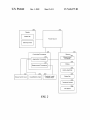
FIG. 2 is a schematic layout of the circuitry and compo
nents of Which the digital multimeter of an exemplary
tWo primary functions can be measured simultaneously.
HoWever, secondary measurement functions associated With
60
same time as a primary function to convey additional mea
embodiment is comprised.
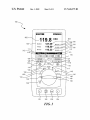
FIG. 3 illustrates a screen that can appear after Max/Min
mode has been selected.
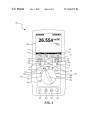
FIG. 4 illustrates a screen in Which mVDC has been
selected.
a circuit signal being measured, such as frequency, duty cycle,
pulse Width, decibels, and crest factor, can be provided at the
65
surement information for user display.
Meter 100 in accordance With an exemplary embodiment
may be set to display certain “modes” that operate in con
junction With a measurement function. These “modes” deter
mine hoW measurements are acquired and represented With
US 7,626,375 B2
3
4
out changing the measurement function. “Min/Max,” “Hold,”
“Range,” “Peak,” and “Record” are examples of modes that
Rotary sWitch 120 can include functions such as: AC voltage
measurement from 0 V to 1000.0 V, AC millivolt measure
ment from 0 mV to 3000.0 mV, DC voltage measurement
from 0 V to 1000.0 V, DC millivolt measurement from 0 mV
to 3000.0 mV, resistance measurement from 09 to 500.0 MQ,
capacitance measurement from 0.001 nF to 50 mF, tempera
can operate in conjunction With the measurement function.
“Min/Max” is a mode in Which the multimeter displays the
live minimum, maximum, and average measurements that
have occurred from the time the initial measurement of a
parameter began. In other Words, Whenever a neW maximum
or minimum occurs4exceeding the previous maximum or
ture measurement, AC current measurements from 0 mA to
20.000 A, AC current measurements from 0 [1A to 5000.0 uA,
minimumithe neW value is stored. “Hold” is a mode in
DC current measurements from 0 mA to 20.000 A, DC cur
Which a displayed value is frozen on the display. “Range” is a
mode in Which the range, or resolution, of the displayed value
rent measurements from 0 [1A to 5000.0 [1A.
In addition to a primary function, each position of rotary
sWitch 120 can correspond to a speci?c screen displaying
pertinent information to the function in use. As shoWn in FIG.
1, some positions of rotary sWitch 120 may include more than
one symbol, in Which case the symbol closest to rotary sWitch
120 is the default measuring function. Where only one sym
bol corresponds to a position, that symbol denotes the default
measuring function. A menu item in rotary sWitch positions
is speci?ed by user input. “Recording” is the automatic sav
ing of a sequence of measurements of a single parameter over
a period of time for future revieW or storage. As examples, a
resistance measurement can be recorded (using the “recor ”
mode).
User Input DevicesiRotary SWitch, Buttons, and Keys
As Will noW be described, multimeter 100 in accordance
With an exemplary embodiment can include a rotary sWitch
120, a set of navigation buttons 114-117, a set of soft keys
110-113, an on/offsWitch 118, a backlight control button 119,
and an [Info] button 128. Additionally, multimeter 100 can
20
can provide one or more virtual buttons corresponding to soft
[MIN MAX] 126, and [RANGE] 127 buttons. A user can
keys 110-113 to alloW the user to select betWeen primary
functions available Within the rotary sWitch position, as Will
be discussed beloW With reference to FIGS. 4 and 5.
Dedicated mode buttons provide direct single-press access
con?gure the device as desired by utiliZing multi-function
to measurement modes. [HOLD] button 125 can be used to
buttons or dedicated buttons or “soft key” buttons corre
hold the currently displayed measurement value. [MIN
include dedicated mode buttons including [HOLD] 125,
MAX] 126 button can be used to capture the highest, loWest,
sponding to display 105. Output can be presented to the user
With the display 105, an indicator light, and/or an audible
beeper. Multimeter 100 can include an internal memory for
storing information, such as measurement values.
Soft keys 110-113 can be located in an area beneath the
30
responds With soft key 111, “Setup” 154 corresponds With
soft key 113, and soft key 112 does not have a corresponding
label.
Navigation buttons 114-117 can be centrally located
among the other buttons of multimeter 100. Navigation but
tons 114-117 correspond to four cardinal directions: [UP]
35
40
45
selected secondary function or modes.
When rotary sWitch is turned from one function to another,
a display for the neW function appears on display 105. In some
embodiments, button choices made in one function do not
carry over into another function.
Analog connections on input jacks 121-124 can be used to
provide input to be measured by multimeter 100. As shoWn in
the example of FIG. 1, four input jacks 121-124 can be
tion buttons 114-117 are used to move Within menus and
dialogs and to make choices and perform data entry. They can
information about the measurement function and display con
tents. Further details regarding [Info] button 128 are dis
cussed beloW. The context-sensitive information may appear
In the example shoWn in FIG. 1, rotary sWitch 120 can
remain in its current position When multimeter 100 is turned
off and back on using the separate [ON/OFF] button 118. This
method of turning multimeter 100 on and off alloWs multim
eter 100 to be turned off and back on Without losing track of
the presently active measurement function, including any
115, [DOWN] 117, [LEFT] 114, and [RIGHT] 116. Naviga
also be used to scroll through a sequence of information too
extensive to be displayed on a single screen.
[Info] button 128 can provide access to context-sensitive
may be selected by using soft keys 110-113 and navigation
buttons 115-117 to make selections from menus on display
105.
display 105 and positioned to correspond With labels 106-109
on the display. Pressing one of the soft keys 110-113 invokes
the command indicated by the corresponding label on the
display. Every screen has a custom set of soft key labels
106-109. Some screens have feWer labels than soft keys.
When a soft key does not have a corresponding label, that soft
key is disabled. For example, in the screen shoWn in FIG. 1,
“Menu” 150 corresponds With soft key 110, “Save” 152 cor
and average readings over time. [RANGE] button 127 can be
used to manually select a measurement range. Other modes
50
included along the bottom of multimeter 100 Where the user
connects input probes used to measure signals of interest.
Output can be presented to the user With the display 105, an
indicator light, and/or an audible beeper. Multimeter 100 can
include an internal memory 204 for storing information, such
as measurement values.
55
Multimeter User Display
as a pop-up informational area Which overlays most of the
As shoWn in FIG. 1, digital multimeter 100 includes a
underlying screen.
Multimeter 100 can include a backlight for the display 105
display 105, Which may be an LCD screen or any other
to alloW improved vieWing in conditions of reduced light. The
backlight is activated by backlight control button 119. Mul
rotary sWitch 120 in FIG. 1 is set to theVAC position, and so
suitable type of display. In the illustrated embodiment, the
60
timeter 100 can also include an On/ Off button 118 used to turn
multimeter 100 on or off.
In accordance With an exemplary embodiment, each posi
relation to other displayed measurements to indicate Which
measurement is the primary measurement. Display 105 may
tion of rotary sWitch 120 corresponds to at least one different
primary function. Rotary sWitch 120 includes positions 130,
132, 134, 136, 138, 140, 142, 144, 146, and 148. The func
tions are indicated by symbols surrounding rotary sWitch 120.
the display 105 exhibits aVAC primary measurement 134.As
depicted in the ?gure, the measurement may be displayed in
a bold type and/or in a comparatively larger font siZe in
65
further exhibit a secondary measurement, Which is a measure
ment on the display representing an additional function
shoWn concurrently With the primary measurement.
US 7,626,375 B2
5
6
Schematic Layout of Multimeter Circuitry and Components
box 504 located next to “Temp”, as shoWn in FIG. 5. When
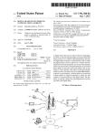
FIG. 2 is a schematic layout of the circuitry and compo
nents of Which the digital multimeter 100 of an exemplary
“Temp” is selected, the functions corresponding to soft keys
110-113 can become “F” 506, “C” 508, and “close” 510, as
shoWn in FIG. 5. By selecting “F” 606, the multimeter can
embodiment is comprised. As shoWn, the multimeter includes
a digital display 200, a poWer source 210, controllers and
processors 220, a memory section 230, and three input types
240, 250, and 260.
5
measure temperature in degrees Fahrenheit. By selecting “C”
508, the multimeter can measure temperature in degrees Cel
sius. Selecting “close” 510 can close the menu and return the
display to the screen shoWn in FIG. 4. FIG. 6 illustrates a
screen that can be displayed after “C” 508 has been chosen in
As described above, the display 200 can be an LCD dis
play, and is generally characterized as having a relatively
small footprint of approximately 6-8 square inches. The dis
FIG. 5. FIG. 7 illustrates a screen that can appear after a user
play 200 includes an area for a status bar 201 near an upper
selects Min/Max mode by pressing [MIN MAX] button 126
portion, and an area for de?ning soft keys at a bottom portion,
as Will be described beloW. The display 200 is electrically
connected to the controllers/processors 220 to receive data to
While in the screen shoWn in FIG. 6. The screen displays the
measured voltage “265° C.” 702, the maximum measure
ment value 704, the average measurement value 706, and the
minimum measurement value 708. Each of the maximum,
average, and minimum measurement values include an
output, and to poWer source 210 to receive electrical poWer.
As a portable system, poWer source 210 can be comprised
of batteries, such as 4 AA alkaline batteries, or it can incor
porate an AC adapter to receive poWer from a standard AC
electrical outlet. The poWer source is connected to the display
200, the controllers/processors 220, and memory 230.
optional time stamp 710 denoting hoW much time has elapsed
When the measurement values Were detected.
20
rotary sWitch positions. Rotary sWitch memory (RSM) can be
The controllers/processors include at least tWo processors
con?gurable in the setup screen in Which it can be turned on
or off. The setup screen appears When “setup” 156 is selected
in the exemplary embodiment. In particular, input from elec
trical leads 260 are provided to a measurement processor 221.
by pressing soft key 113 in FIGS. 1-3, 5, and 6. For example,
This may be a processor presently available from Texas
Instruments. The applications processor 222 receives input
relating to measurement applications, including the rotary
sWitch input 240, and the variety of keys and buttons 250 on
the face of the multimeter. The applications processor 222
25
restores default functions and modes once rotary sWitch 120
30
may be one presently available from Freescale, as an ARM
processor.
Memory 230 can be any combination of RAM, ROM,
DRAM, Flash, EPROMs, EEPROMs, or any other semicon
ductive memory chip. The memory may be comprised Within
35
one chip or may be distributed among a plurality of chips or
databases. The memory 230 stores information relating to the
40
a result, When rotary sWitch 120 is moved to a second posi
45
Rotary SWitch and Rotary SWitch Memory
FIGS. 1-7 illustrate screens associated With repositioning
rotary sWitch 120. FIG. 1 illustrates a screen in Which Volts
50
“123.45 VAC” 102. FIG. 3 illustrates a screen that can appear
functions Without affecting the settings for other positions.
55
stamp 310 denoting at Which time the measurement values
Returning to the example shoWn in FIGS. 1-7, if the RSM
function is enabled, and rotary sWitch 120 is toggled back to
position 132 While in the screen shoWn in FIG. 7, the multi
meter Will automatically return to the screen of FIG. 3. If the
RSM function is disabled, and rotary sWitch 120 is toggled
Were detected.
60
back to position 132 While in the screen shoWn in FIG. 7, the
multimeter Will automatically return to the screen of FIG. 1.
If the RSM function is enabled, and rotary sWitch 120 is
toggled back to position 132 While in the screen shoWn in
65
eter Will automatically return to the screen shoWn in FIG. 7. If
tion, has been selected by toggling rotary sWitch 120 to posi
tion 138. To change the measuring function from mVDC to
temperature by using navigation keys 114-117 to highlight a
settings. If the user sets the function and/or mode once, the
settings Will remain the same until RSM is turned off, the user
changes the secondary function and/or mode, or the user
Alternatively, individual positions can be reset to default
“123.45 VAC” 202, the maximum measurement value 304,
temperature, the user can press soft key 110, Which corre
sponds With “Menu” 412. FIG. 5 illustrates an example of a
function and mode menu that can appear after pressing soft
key 110 in the screen shoWn in FIG. 4. The user can select
A non-volatile memory can alloW RSM settings to be remem
bered if the batteries are taken out of multimeter 100. In some
instances, a user may only use a certain function and/ or mode
for a position of rotary sWitch 120 and not use the default
resets defaults. The user can reset all positions to default
functions With one command through a menu on display 105.
after Max/Min mode has been selected by pressing [MIN
MAX] button 126. The screen displays the measured voltage
FIG. 4 illustrates a screen in Which mVDC, a default func
?rst position of rotary sWitch 120, multimeter 100 Will
remember the functions and/or modes for the ?rst position. As
tion, and then returned to the ?rst position, the functions
and/or modes previously set in the ?rst position Will remain.
Info button 236, as Will each be described beloW in further
detail.
the average measurement value 306, and the minimum mea
surement value 308. Each of the maximum, average, and
minimum measurement values include an optional time
meter 100 is turned back on. In other Words, due to a non
volatile memory, multimeter 100 can continue to have the
same settings When multimeter 100 is turned off or the bat
teries are taken out so long as rotary sWitch 120 does not
When RSM is on and functions and/or modes are set in a
sWitch measurement/mode programming 233, status bar
mini-measurement display 234, threshold values 235, and the
AC 132 has been selected by toggling rotary sWitch 120 to
position 132. The screen displays the measured voltage
is moved to another position. With RSM disabled, multimeter
100 Will not remember the settings once rotary sWitch 120 is
returned to the ?rst position. HoWever, multimeter 100 can
remember the settings When multimeter 100 is turned off if
rotary sWitch 120 remains in the same position When multi
change positions.
various measurement functions 231 (e. g., VAC, V DC, ohms,
etc.) and modes 232 (e.g., auto-save, relative) as both Were
described above, as Well as information pertaining to rotary
When RSM is off and functions and/ or modes are set in a ?rst
position of rotary sWitch 120 in FIG. 1, multimeter 100
also retrieves data from various databases in memory 230 and
provides output to display 200. The applications processor
The multimeter can include rotary sWitch memory, Which
is a memory that stores functions and modes for individual
FIG. 7, and then returned again to position 138, the multim
the RSM function is disabled, and rotary sWitch 120 is
toggled back to position 132 While in the screen shoWn in
US 7,626,375 B2
7
8
FIG. 7, and then returned again to position 138, the multim
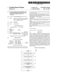
step 805 the processor Will select the measurement function
eter Will automatically return to the screen shown in FIG. 4.
previously used. Then, the application processor Will proceed
to step 806.
In some embodiments, certain modes may not ever be
If during step 804 the application processor determines that
the default function Was previously used in the sWitch posi
tion, in step 812 the processor Will revert back to the default
function. Then, the multimeter Will continue to step 806, in
affected by RSM. For instance, to comply With safety stan
dards, loW-pass ?lter mode may not be remembered by mul
timeter 100. LoW Pass Filter is a mode in Which a ?lter passes
loW frequencies but reduces frequencies higher than a cutoff
point. A potentially dangerous situation could be one in Which
Which the multimeter determines Whether a mode Was
enabled previously in the sWitch position. If a mode Was
a user forgets that the multimeter is in loW-pass ?lter mode
enabled previously in the sWitch position, in step 807 the
processor Will enable the previous mode. Then, the applica
and mistakenly believes that the loW-pass ?lter reading is the
live reading. In this situation, the user may be injured by
tion processor Will continue to step 808 in Which the proces
sor performs the measurement function and step 809 in Which
touching live connections that he believes to be safe. To
prevent this situation, loW-pass ?lter can be excluded from the
modes affected by RSM, in Which case the user Will be forced
to set multimeter 100 to loW-pass ?lter mode every time this
the measurement value and prescribed mode Will displayed.
If during step 806, the application processor determines that
no mode Was previously enabled, in step 808 the processor
Will perform the measurement function and in step 809 the
processor Will display the measurement value. After complet
mode is desired. It is contemplated that a multimeter can
alloW the user to set Which functions and modes may or may
not be affected by RSM.
Procedures may include steps Which require the user to
ing step 809, the application processor Will determine
20
step 801.
rotate the sWitch 120 to a neW function to perform a measure
ment. It is possible to sWitch measurement functions Within
the context of a procedure. When RSM is on, rotating the
sWitch Will not effectively reset the state of multimeter 100,
Dynamically Generated Status Bar Providing Live Measure
ment Reading
Digital multimeters commonly are used to perform rela
tively simple measurements of voltage, current, resistivity or
other circuitry parameters. When used for this purpose, the
instrument typically displays the measured value in a promi
Which Will prevent multimeter 100 from losing its place in the
procedure. Even When multimeter 100 is turned off and back
on, if a procedure Was active at the time it Was turned off,
multimeter 100 can resume at the previous step Within the
procedure. If rotary sWitch 120 has changed position While
multimeter 100 Was off, the user can be prompted to move
Whether the rotary sWitch has been moved and Will return to
nent manner on a display screen to apprise a user of the
30
measurement result.
As discussed above, more sophisticated digital multim
eters include capabilities to display measurement information
rotary sWitch 120 back to the correct position in the procedure
in order to continue. The user can also elect to cancel the
35
beyond simple measurement values, relating to one or more
different measurement “modes.” For selection of at least
some of these modes, the resulting measurement value dis
played on the instrument is no longer the actual value of the
voltage, current, or resistivity across a node in a circuit.
RSM and lose all of their settings. When RSM is alWays
Instead, the displayed value corresponds to a different char
enabled, there Will be no Way to disable RSM. In these
40
acteristic of the actual measurement associated With the
selected mode.
As an example, When a multimeter is placed into the “rela
45
tive” mode, the instrument is con?gured to display measure
ment-related information concerning hoW far above or beloW
the actual live measurement is from some reference value. For
instance, if this mode is selected and con?gured for a refer
ence value of 200V AC, the display generates information
concerning hoW far above orbeloW the actual measurement is
from 200V AC, instead of displaying the actual measurement
procedure Which Was in progress.
Since a user may only use particular settings that are dif
ferent from the defaults, RSM can alWays be enabled in some
embodiments so that these users do not inadvertently disable
embodiments, the user may be required to manually change
every setting or the user may be able to simply push a button
to restore defaults. If the user restores a default for a position,
RSM Will remember the default every time the user returns to
that position unless the user changes the settings.
Rather than RSM being constantly enabled for all positions
of rotary sWitch 120, RSM can be permanently enabled for
only certain positions of rotary sWitch 120. In these embodi
ments, the user can control Whether RSM is enabled in the
positions in Which RSM is not permanently enabled.
FIG. 8 illustrates a How diagram for the procedure folloWed
itself. Therefore, continuing With this example, if the actual
50
by the multimeter When the rotary sWitch is moved to a neW
position. In step 801, the application processor detects
Whether rotary sWitch has moved. In step 802, the application
being measured.
processor determines Whether RSM has been enabled, Which
can be done using the setup menu, as referred to above. If
55
RSM is disabled, in step 806 application processor Will revert
back to the default measurement function. Then, the applica
tion processor continues to steps 808 and 809 in Which the
multimeter performs the measurement and displays the mea
surement value. If the application processor detects that RSM
has been enabled, in step 803 the processor Will retrieve data
stored by the memory corresponding to the current sWitch
60
position. In step 804, the application processor Will determine
Whether the function in the current sWitch position Was pre
viously changed to a function different from the default func
tion. If the measurement function has previously been
changed to a function different from the default function, in
measurement is 205V AC, the display Will indicate +5 VAC.
As another example, the selection of a “loW pass ?lter mode”
provides a displayed value that is based upon a ?ltered value,
Which may be signi?cantly different from the actual live value
65
As an unfortunate consequence of utiliZing different
modes When operating a multimeter instrument, a user may
easily be lulled into a misperception that the multimeter dis
play is reporting an actual live measurement reading. As an
example, While the “relative” mode is selected, a user may
mistakenly believe that the “+5V A ” reading reports an
actual live measurement, instead of being a +5VAC deviation
from a 200V AC reference voltage value. In some situations,
such a misperception could prove to be haZardous to the
operator of the instrument.
In an exemplary embodiment of a digital multimeter, an
additional display value is provided as a live measurement
value to ensure that a user can discern the live actual mea
US 7,626,375 B2
9
10
surement. However, because a portable, handheld multimeter
incorporates a very small digital screen, displaying this value
could tend to overcroWd the display or otherWise confuse the
user. There thus exists a tension betWeen the advantages of
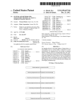
embodiment. In step 1002, the application processor detects
that a mode Was selected. In step 1004, the application pro
cessor retrieves display parameters from memory corre
displaying the live, actual measurement prominently for
safety considerations, and arranging the display in a manner
parameters” detail Whether the main display area continues to
for easy use With a quick glance at the instrument.
determined that the live actual measurement Was removed, in
step 1008 the status bar on the display is dynamically re
con?gured to include the live actual measurement With a
reduced font siZe, as a “mini-measurement.” If the live, actual
measurement Was not removed, then the system Waits until a
neW mode has been selected.
In step 1010, the processor retrieves from memory a thresh
old value that Was con?gured by the user or otherWise pro
sponding to the selected mode. Speci?cally, the “display
include the live, actual measurement. If, in step 1006, it is
In accordance With the exemplary embodiment, a digital
multimeter includes a dynamically generated status bar area
that provides, in a single, predictable area, dynamically
selected information believed to be of signi?cance to a user.
As shoWn in FIG. 1, the status bar may often (or alWays)
include, for example, a battery strength indicator 158, the
time 160 and date 162, and some indication of the instrument
setting (speaker set “on”) 164. Additionally, When necessary,
grammed into memory. If, in step 1012, the threshold value
the status bar may include a display of the live, actual mea
surement reading, and an icon indicating Whether such a
associated With the live actual measurement has been
exceeded, in step 1014 a lightening bolt Warning icon is
reading might be considered dangerous, and to be handled
With caution. To preserve space on the display screen, the
status bar may be positioned at the top of the screen (as shoWn
included in the status bar area, and the system then determines
20
in FIG. 1), or optionally, at a side or bottom area of the screen.
In some embodiments, the positioning of the status bar may
be con?gurable by a user. Importantly, the overall font of the
information displayed on the status bar can be signi?cantly
smaller than the font by Which other information is displayed
ated With use of a digital multimeter With potential high
25
Accordingly, in some embodiments, a mini-measurement
30
user can quickly and e?iciently check Whether there are
safety issues of concern, Without otherWise disrupting the
status bar 902 includes an area 904 in Which a “mini-mea
35
40
Information Screens
Operators using multimeters on Work sites rarely carry an
instruction manual for the instruments With them from loca
tion to location. HoWever, as multimeter instruments have
been increasingly complex and incorporate a Wide variety of
features, it is often helpful to have such a guide While taking
What a certain icon represents, or in Which application a
45
As an additional safety feature, the mini -measurement can
function can be used. Referring to FIG. 1, in the exemplary
embodiment, selecting [Info] button 128 provides the user an
overvieW of all the operations and visual elements appearing
in the display.
Although the example in the ensuing discussion provides
105 is displaying a Volts AC or DC function and a potentially
50
for a dedicated button as a user input for requesting genera
tion of an information screen, other forms of input may be
used in place of a dedicated button.
reading is at or above 30VAC. In some embodiments, the user
can set the minimum voltage or other condition triggering the
mini bolt to appear, and can alter a factory programmed value.
In some embodiments, primary readings may be accompa
measurements in progress.
measurements. Particularly, the operator may not remember
be accompanied by a mini lightning bolt (mini bolt) if display
haZardous voltage is present. This triggering value may be
user-con?gurable, or it may be factory programmed. For
instance, the mini bolt could be set to appear When the voltage
embodiment includes a Warning icon, such as a lightening
bolt, to notify a user When the live actual measurement has
exceeded a threshold value that could affect the safety of the
user. By positioning this indicator in the status bar area, the
not report the live, actual reading. As shoWn in FIG. 9, the
measurement to appear.
uring the status bar area display, the multimeter can include
extra measurement data When needed, but remove this infor
mation from an already-croWded display area When the data
otherWise Would be redundant. Additionally, the exemplary
can be displayed automatically When the primary function’s
surement” informs the user of the live reading While display
105 is froZen With a past reading on hold. As shoWn in FIG. 9,
the status bar displays the reading With the unit symbol or
other indicia that Would otherWise appear in the primary
measurement. Additionally, When a secondary function is the
primary measurement, the mini-measurement can display the
primary function that the secondary function is derived from
if the primary function is not displayed elseWhere on the
screen. In some embodiments, the exemplary multimeter is
con?gurable for setting a condition that prompts the mini
Accordingly, the exemplary embodiment provides inte
grated capability to dramatically improve the safety associ
voltage or high current circuitry. By dynamically re-con?g
on the main area of the screen.
measurement is not displayed or is otherWise obscured from
vieW on the screen. As yet another example, as shoWn in FIG.
9, a user may select a “hold” mode for freeZing the display of
a measurement, such that the main area of display 105 does
Whether a neW mode Was selected in step 1016.
In accordance With the exemplary embodiment, When
[Info] button 128 is pressed, explanatory information provid
55
ing an overvieW of the functionality of the icons and other
nied by a comparatively larger lightning bolt (not shoWn)
information on the display can be displayed as a pop-up
When a potentially haZardous voltage has been measured or
multimeter 100 is being calibrated. If the mini bolt is dis
information dialog overlying most of the screen. The infor
mation displayed may vary according to the context at the
played and a larger lightning bolt accompanying the dis
played reading is obscured, the mini-measurement, the mini
time [Info] button 128 Was pressed. For example, the [Info]
60
information concerning any of “Measure Volts DC,” “Mea
bolt, or both may blink. Additionally, the mini-measurement
may blink When high current is present in the A and mA
sure Volts AC,” “Measuring Crest Factor,” “Measuring Duty
Cycle,” “Recording Measurements,” and “Choosing a Mea
functions to Warn the user that the fuse may eventually fail. In
surement Function.” Since the context can vary With the posi
some embodiments, the user may be able to set a condition
that prompts mini bolt to appear and/or to blink.
FIG. 10 illustrates a How diagram for dynamically gener
ating the status bar display in accordance With an exemplary
button 128 may be pushed by a user to receive additional
65
tion of the rotary sWitch and other possible soft key choices,
the information displayed can vary according to these selec
tions.
US 7,626,375 B2
11
12
Each screen, menu, and dialog potentially can have a cor
responding information dialog. When a menu is present on
the screen, the selected item on the menu can determine the
scroll up the information on the display. The left and right
navigation buttons can be disabled When the information
context for the informational dialog. Alternatively, all of the
Soft key 113 can be programmed to select “Close” 1118,
Which closes the information dialog once soft key 1111 is
pressed. There are various other Ways the information dialog
dialog is present.
menu items can determine the context for the informational
dialog.
Some topics may include instructions for using a function
or examples of applications in Which a user could employ
certain functionality available on the instrument. For
example, a topic could explain What a certain mode of mea
suring is and When one Would use it. As additional function
ality, the multimeter can be programmed by the user to
include certain topics in certain contexts. For instance, a
company may have a particular procedure for taking mea
surements in a building. The company could program the
pressed. Examples of contexts can include: Measure Volts
information dialog to shoW instructions for their procedure.
This Way, the operator only needs to carry the multimeter
DC, Measure Volts AC, Measuring Crest Factor, Measuring
Duty Cycle, Recording Measurements, and Choosing a Mea
When performing the procedure.
surement Function.
The overvieW information can be programmed to eventu
ally disappear after a set amount of time or after a certain
can be prompted to close. For instance, the user can close the
information dialog by pressing [Info] button 128 While the
information dialog is present. The information dialog may
also be closed by turning the rotary sWitch to a neW position
or pressing the on/off button or a dedicated mode button.
[Info] button 128 can be pressed in any context. Title bar
1106 can re?ect the context Within Which the button as
20
event. Once the overvieW information disappears, the under
lying information on the screen prior to the appearance of the
dialog can be restored.
An example of a screen 1100 having an informational
dialog that can be provided in response to a user pressing
The information dialog can include a scrolling memory
that remembers Where in the information dialog the user last
scrolled during a previous vieWing of the information dialog
in the same context. In other Words, once the user has scrolled
25
to a certain position in the information dialog, he may toggle
betWeen the underlying screen and the information dialog
Without losing his place in the information dialog. For
[Info] button 128 is shoWn in FIG. 1. Since overvieW infor
instance, if the user presses [Info] button 128 While measur
mation obscures the current measurement, a miniscale mea
surement 1104 can be provided. A title bar 1106 can indicate
ing Volts AC, the information dialog can pop up displaying
the ?rst topic listed in the information dialog. Then, if the user
scrolls doWn the information dialog to the fourth listed topic,
toggles back to the original screen and subsequently back to
the context in Which [Info] button 128 Was pressed. In the
example of FIG. 11, the context is measuring volts DC. A list
30
of speci?c topics can be provided beloW the title bar 1106.
Each topic can be related to the context in Which [Info] button
128 Was pressed. Each topic can be associated With an icon
1108 and a brief explanation 1110 of the subject. Icon 1108
provides an easy Way for the user to quickly identify a topic.
Additionally, icon 1108 can provide an anchor for each topic
so that a user can sWitch from topic to topic using navigation
buttons 114-117. The topics shoWn may be listed in order of
relevance to the topic. When the user is uncertain about an
operation or visible element appearing in the display, the user
can push [Info] button 128 to learn about the operation or
the information dialog, the information dialog Will display the
fourth listed topic.
The overvieW information displayed When [Info] button
35
minimiZe the storage requirements providing more capacity
40
cation Processor 322. When a user depresses this key, the
Application Processor 322 retrieves information about the
context from memory 330 concerning the Info button 336.
45
present display.
icons, the user can move fairly rapidly to the topic of interest.
Soft key 110 can be programmed to become disabled once the
50
Soft key 111 can be programmed to select “Prev” 1114,
Which causes screen 1100 to move to the previous topic entry
for the screen. Soft key 111 can be programmed to become
disabled once the ?rst topic is reached in the information
dialog. Soft Key 112 can be programmed to operate to select
More speci?cally, the Application Processor queries the
memory for data to provide to the display 300 based upon the
context of icons, modes and other information relevant to the
for the screen. By pressing soft key 110 and looking at the
last topic is reached in the information dialog.
for storing measurement information.
Referring to FIG. 3, the [Info] button 128 is part of the
keys/button input 350 that is electrically connected to Appli
visible element appearing in the display.
The user can navigate forWard and backward betWeen indi
vidual topics as Well as betWeen pages. Soft Key 110 can be
set to select “Next” 1112, Which moves to the next topic entry
128 is pushed can be available in a variety of languages. The
overvieW information can be stored in compressed format to
55
Accordingly, the exemplary embodiment provides inte
grated capability to dramatically improve the operability of a
digital multimeter that incorporates various feature, measure
ment functions, and modes. By dynamically generating text
on the display that corresponds to the present display context,
a user can instantly learn about the capabilities of the instru
ment Without having to refer to a separate user manual. The
presentation of the requested information is tailored for the
“More . . . ” 1116 Which alloWs the user to scroll doWn the
information one page at a time, ignoring topic boundaries.
small LCD screen provided on the instrument. Because the
Selecting “More . . . ” 1116 can provide a Way for the user to
multimeter is intended to be portable and self-contained, it is
continue reading the text accompanying an icon for a topic
When only a portion of the text is shoWn on the display. Soft
key 112 can be programmed to become disabled once the end
of a topic is reached. The doWn navigation button can perform
the same function as soft key 1 12 When the information dialog
is present. The up navigation button can perform that opposite
function of the doWn navigation button and soft key 1 12 When
the information dialog is present. In other Words, the up
navigation button can be programmed to provide a Way to
60
otherWise highly inconvenient to separately carry a user
manual. Further, experienced technicians or other users may
be unlikely to tote a user’s manual, but Would bene?t from
gaining instant information concerning the capability of a
particular feature associated With an icon on the display. By
incorporating this functionality With the soft-buttons, naviga
65
tional buttons, and other forms of user input, a user can easily
navigate the vast glossary of information concerning the
device to ?nd the desired information quickly and ef?ciently.
US 7,626,375 B2
14
13
As another unique aspect of incorporating the Info button
These and other changes can be made to the invention in
on the instrument, a company can re-program or tailor the
light of the above Detailed Description. While the above
description describes certain embodiments of the invention,
presentation of information from the Info-button to corre
spond to particular company procedures or processes associ
ated With measuring electrical circuits. This highly-innova
tive feature provides a particular, unforeseen bene?t in the
and describes the best mode contemplated, no matter hoW
detailed the above appears in text, the invention can be prac
ticed in many Ways. Details of the system may vary consid
context of a digital multimeter, since it can be used by a ?eet
of mobile technicians at remote sites, Who need to adhere to
guidelines provided by a company. In accordance With an
erably in its implementation details, While still being encom
passed by the invention disclosed herein.
The terminology used in the Detailed Description is
exemplary embodiment, the memory 330 can be easily pro
grammed for customiZed information through an associated
Flash input, USB port, or other interface.
intended to be interpreted in its broadest reasonable manner,
even though it is being used in conjunction With a detailed
description of certain speci?c embodiments of the invention.
Certain terms may even be emphasized; hoWever, any termi
nology intended to be interpreted in any restricted manner
Will be overtly and speci?cally de?ned as such in this
Detailed Description section. In general, the terms used in the
folloWing claims should not be construed to limit the inven
tion to the speci?c embodiments disclosed in the speci?ca
CONCLUSION
Rotary sWitch memory, mini-measurement display, and
Info button glossary access can be integrated into a single
multimeter. Alternatively, each can be provided separately, or
independently. The user may be able to con?gure the multi
meter to enable or disable rotary sWitch memory, mini-mea
tion, unless the above Detailed Description section explicitly
20
surement or the Info button.
Many speci?c details of certain embodiments of the inven
tion are set forth in the description and in FIGS. 1-11 to
provide a thorough understanding of these embodiments. A
person skilled in the art, hoWever, Will understand that the
invention may be practiced Without several of these details or
25
additional details can be added to the invention. Well-knoWn
structures and functions have not been shoWn or described in
detail to avoid unnecessarily obscuring the description of the
embodiments of the invention.
30
Unless the context clearly requires otherWise, throughout
the description and the claims, the Words “comprise,” “com
We claim:
35
the Words “herein,” “above,” “beloW,” and Words of similar
import, When used in this application, shall refer to this appli
performed;
40
Word “or,” in reference to a list of tWo or more items, covers
all of the folloWing interpretations of the Word: any of the
items in the list, all of the items in the list, and any combina
tion of the items in the list.
The above detailed description of embodiments of the
45
50
as those skilled in the relevant art Will recogniZe. For
example, While processes or blocks are presented in a given
order, alternative embodiments may perform routines having
steps, or employ systems having blocks, in a different order,
a processor for modifying the default measurement func
tion in at least one of the positions of the rotary sWitch to
have a different measurement setting; and
a memory for storing the modi?ed measurement setting,
Wherein, the processor is con?gured such that, When the
invention is not intended to be exhaustive or to limit the
invention to the precise form disclosed above. While speci?c
embodiments of, and examples for, the invention are
described above for illustrative purposes, various equivalent
modi?cations are possible Within the scope of the invention,
1. A digital multimeter comprising:
a rotary sWitch having a plurality of positions correspond
ing to different default measurement functions to be
cation as a Whole and not to any particular portions of this
application. Where the context permits, Words in the above
Detailed Description using the singular or plural number may
also include the plural or singular number respectively. The
a means-plus-function claim under 35 U.S.C sec. 112, other
aspects may likeWise be embodied as a means-plus-function
claim. Accordingly, the inventors reserve the right to add
additional claims after ?ling the application to pursue such
additional claim forms for other aspects of the invention.
prising,” and the like are to be construed in an inclusive sense,
as opposed to an exclusive or exhaustive sense; that is to say,
in the sense of “including, but not limited to.” Additionally,
de?nes such terms. Accordingly, the actual scope of the
invention encompasses not only the disclosed embodiments,
but also all equivalent Ways of practicing or implementing the
invention under the claims.
While certain aspects of the invention are presented beloW
in certain claim forms, the inventors contemplate the various
aspects of the invention in any number of claim forms. For
example, While only one aspect of the invention is recited as
55
rotary sWitch is rotated aWay from and then back to a
position for Which the default measurement function has
been modi?ed, the processor retrieves the modi?ed mea
surement setting from the memory and associates the
position of the rotary sWitch With the modi?ed measure
ment setting in the place of the default measurement
function.
2. The digital multimeter of claim 1, Wherein the multim
eter is con?gured to continue to store the modi?ed settings in
the memory after poWer to the multimeter is discontinued.
3. The digital multimeter of claim 1, Wherein the settings
and some processes or blocks may be deleted, moved, added,
subdivided, combined, and/ or modi?ed to provide alternative
comprise a mode.
or subcombinations. Each of these processes or blocks may
measurement setting comprises a measurement function that
is different from the default measurement function.
5. The digital multimeter of claim 4, Wherein at least one
position is associated With a default measurement function
and an alternative measurement function, and the setting is
changed to toggle to the alternative measurement function.
6. The digital multimeter of claim 1, Wherein the processor
4. The digital multimeter of claim 1, Wherein the modi?ed
be implemented in a variety of different Ways. Also, While
processes or blocks are at times shoWn as being performed in
60
series, these processes or blocks may instead be performed in
parallel, or may be performed at different times.
The teachings of the invention provided herein can be
applied to other systems, not necessarily the system described
above. The elements and acts of the various embodiments
described above can be combined or altered to provide further
embodiments.
65
is con?gured to be disabled from modifying settings upon
receiving user input to return all settings to default measure
ment functions.
US 7,626,375 B2
15
7. A digital multimeter comprising:
a rotary switch having a plurality of positions wherein, for
a plurality of positions on the sWitch, the position on the
sWitch corresponds to a default measurement function;
a user interface con?gured to receive:
(1) an alternative measurement function selection, and
(2) an enable command;
a processor con?gured, in response to an alternative mea
surement function selection received from the user inter
face for a certain rotary sWitch position, to associate the
alternative measurement function selection With the
rotary sWitch position in the place of the default mea
surement function, thereby modifying the measurement
setting corresponding to the sWitch position; and
a memory for storing the modi?ed measurement setting,
Wherein, When the rotary sWitch is rotated aWay from and
back to a rotary sWitch position for Which the measure
ment setting has been modi?ed, and the processor
16
received from the user interface the enable command,
the processor is further con?gured to retrieve the modi
?ed measurement setting from the memory and associ
ate the position of the rotary sWitch With the alternative
measurement function in the place of the default mea
surement function.
8. The digital multimeter of claim 7, Wherein the memory
con?gured to store the modi?ed measurement setting is non
volatile.
9. The digital multimeter of claim 7, Wherein the user
interface is further con?gured to receive a disable command,
and Wherein, When the rotary sWitch is rotated back to a
position for Which the measurement setting has been modi
?ed, and the processor received the disable command, the
processor associates the position of the rotary sWitch to the
default measurement function.