1
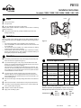
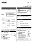
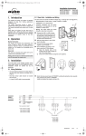
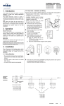
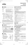
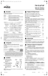
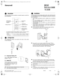
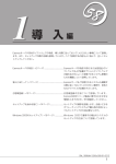
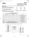
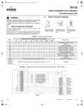
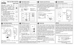
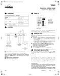
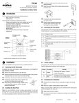
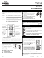
TH1 1 4
User s Guide
Non-programmable Thermostat
1.
Description
Aube’s TH114 Series non-programmable thermostats can be used
to control ambient or floor temperature. The following models are
available:
A model:
Ͽ
controls and displays the ambient temperature
F model:
Ͽ
controls and displays the floor temperature
uses an external temperature sensor
Ͽ
AF model:
Ͽ
Ͽ
Ͽ
controls and displays the ambient temperature
maintains the floor temperature within desired
limits
uses an external temperature sensor
GFCI fault light *
Arrow appears
when the setpoint
is displayed
Power output
Actual or setpoint
temperature
3.
n
Installation
Refer to the installation instructions of the
power base.
o
Insert the tabs at the top of the control
module in the slots at the top of the
power base.
p
Secure the control module using the captive screw underneath the base.
Note: Do not obstruct the thermostat's vents.
4.
Power-up
As soon as the thermostat is powered, it undergoes a
series of tests before displaying the actual temperature.
5.
Error Messages
The measured temperature is below 0°C (32°F). Heating is turned On.
GFCI fault indicator *
1 to 24%
25 to 49%
50 to 74%
75 to 99%
100%
The measured temperature is above 50°C (122°F) (A
or AF model) or 60°C (140°F) (F model).
Temperature
adjustment button
The floor sensor is defective or not properly connected
(F model only), or the thermostat is defective.
GFCI test button * /
Backlight button *
On/Standby button
6.
GFCI Test
* available on certain models only
Each thermostat consists of a control module which must be
mounted on a PB112 Series power base. For the selection and
installation of the power base, refer to its installation instructions.
2.
DIP Switch Configuration
The DIP switches are located at
the back of the control module.
2.1 Temperature Display (S1 )
Note: This procedure must be performed if the thermostat is
mounted on a GFCI-equipped power base.
Test the GFCI immediately after installing
the control module, and once a month thereafter.
n
Raise the temperature
until the heating power indicator
appears.
o
p
Press the Test button.
q
If the test has failed, cut power to the heating system from the
main electrical panel and call customer service.
To switch between °C and °F.
2.2 Model (S2)
Note: Available on certain models only
F:
To select the F model
AF: To select the A or AF model
If the test is successful, you will hear a
click caused by the GFCI relay tripping.
The heating power indicator will disappear, GFI will appear and the Fault light
will illuminate. Reset the thermostat by
switching it to Standby and back to On.
Note: If the Fault light is On during normal operation, cut power to
heating system at the main electrical panel and have an electrician
verify the installation.
TH114
400-114-000-B
21/2/05
1/2
7.
8.
Operation
Technical Specifications
Power supply: Refer to the power base installation instructions.
7.1 Backlight
When either of the
buttons is pressed, the display is lit for 10
seconds. The setpoint appears for 5 seconds, then the actual temperature is displayed.
When the backlight button is pressed, the display is lit for 5 seconds. NOTE: If the thermostat is mounted on a GFCI-equipped
power base, this button is used for the GFCI test.
Ambient setpoint range (A/AF models): 5°C to 30°C (40°F - 86°F)
Floor limit range (AF model): 5°C to 40°C (40°F - 104°F)
Floor setpoint range (F model): 5°C to 40°C (40°F - 104°F)
Setpoint resolution: ± 0.5°C (1.0°F)
Display resolution: ± 0.5°C (1.0°F)
Duty cycle: Refer to the power base installation instructions.
Storage: -20°C to 50°C (-4°F - 120°F)
7.2 Displaying and Setting the Temperature
The thermostat normally displays the actual temperature. To view
the setpoint, press once on one of the
buttons. The setpoint is
displayed for 5 seconds. During the setpoint display, press one of
the
buttons to change it. To scroll the setpoint faster, press
and hold the button.
7.3 Setting the Floor Temperature Limits (AF model only)
The thermostat generally turns heating On or Off to control the ambient temperature. However, if the floor temperature drops below the set minimum floor temperature
limit or rises above the maximum limit, the thermostat
will turn heating On or Off respectively, regardless of the
ambient temperature, to maintain the floor temperature
within the desired limits.
The minimum and maximum floor temperature limits are
factory-set at 10°C (50°F) and 28°C (82°F) respectively. To modify
the limits, proceed as follows:
n
o
Switch the thermostat to Standby.
p
Press the Test button briefly to switch between minimum and
maximum floor temperature settings.
q
r
Press the
While pressing any button, switch the thermostat back to On to
access the floor temperature limit settings.
buttons to set the desired limit.
Press the Test button for 3 seconds to save your modifications.
After the data are saved, the thermostat displays the actual
ambient temperature or “– –”.
Note: Your modifications are also saved if no button is pressed for
60 seconds.
s
9.
Warranty
AUBE TECHNOLOGIES INC. ONE (1) YEAR LIMITED WARRANTY
This product is guaranteed against workmanship defects for a one
year period following the initial date of purchase. During this period,
AUBE Technologies Inc. will repair or replace, at our option and
without charge, any defective product which has been used under
normal conditions.
The warranty does not cover delivery costs and does not apply to
products poorly installed or randomly damaged following installation. This warranty cancels and replaces any other manufacturer's
express or implied warranty as well as any other company commitment.
AUBE Technologies Inc. cannot be held liable for related or random
damages following the installation of this product. The defective
product as well as the purchase invoice must be returned to the
place of purchase or mailed, prepaid and insured, to the following
address.
1 0. Service
705 Montrichard
Saint-Jean-sur-Richelieu, Quebec
J2X 5K8
Canada
T: (450) 358-4600
1-800-831-AUBE (2823)
F: (450) 358-4650
[email protected]
For more information on our products, visit us at:
www.aubetech.com
Switch the thermostat to Standby and back to On to reset the
GFCI and return to the normal display.
:
TH114
400-114-000-B
21/2/05
2/2
PB112
Installation Instructions
For models: 120GA / 120GB / 120S / 240GA / 240GB / 240S / 240D
n
n
o
p
Parts
1.
Figure 1
Power
One (1) power base
Two (2) screws
Four (4) solderless connectors for copper wires
NOTE: Special CO/ALR solderless connectors must be used for connecting
aluminum conductors.
q
One (1) floor sensor and one (1) flat tip screwdriver (F and AF floor
heating models only).
o
Guidelines
2.
Load
Turn off power to the heating system at the main electrical panel to
avoid electrical shock. The installation should be carried out by an electrician.
Figure 2
High voltage thermostats must be installed onto an electrical box.
For a new installation, choose a location about 5 ft. above the floor and
on an inside wall.
The thermostat must be installed on an inside wall facing the heating
system (except for floor heating systems).
Avoid locations where there are air drafts (top of staircase, air outlet),
dead air spots (behind a door), direct sunlight or concealed chimneys or
stove pipes (except for floor heating systems).
p
Procedure
3.
n
Connect the power base wires to the power supply and load using solderless connectors for copper wires (figure 1).
o
If your thermostat is type F or AF (not A), insert the floor sensor wires
through one of the two holes below the terminals (figure 2) and connect
the wires to terminals 3 and 4 (no polarity).
The wires must run alongside the terminals and not go over them. The
wire must not cross any heating wires nor be placed directly on a heating
wire or adjacent to it. For best performance, the sensor probe should be
centered between the wires in the mat.
p
If you wish to use a remote controller such as the CT240 or CT241,
insert the cable (use 18 to 22 gauge flexible wires) into one of the two
holes available below the terminal board and connect to terminals 1 and
2 of the base (figure 2).
q
4.
Technical Specifications
Model
Supply
Max. Load
Power
Wiring
GFCI
120GA
120 VAC, 50/60Hz
15 A
1800 W
4w/DP
5 mA
30 mA
120GB
120 VAC, 50/60Hz
15 A
1800 W
4w/DP
120S
120 VAC, 50/60Hz
16.7 A
2000 W
4w/SP
240GA
240 VAC, 50/60Hz
208 VAC, 50/60Hz
15 A
3600 W
3120 W
4w/DP
5 mA
240GB
240 VAC, 50/60Hz
208 VAC, 50/60Hz
15 A
3600 W
3120 W
4w/DP
30 mA
q
Push the excess length of the high-voltage wires back into the electrical
box.
240S
240 VAC, 50/60Hz
208 VAC, 50/60Hz
16.7 A
4000 W
3475 W
4w/SP
r
s
Secure the power base to the electrical box using the provided screws.
240D
240 VAC, 50/60Hz
208 VAC, 50/60Hz
15 A
3600 W
3120 W
4w/DP
t
u
Install the control module onto the base.
If necessary, set the configuration switches on the control module (refer
to the control module user guide).
Apply power to heating system.
Storage: -4°F to 120°F (-20°C to 50°C)
Remote controller input (ECONO): requires a dry contact
Size (H • W • D): 4.89 x 2.76 x 0.91 in. (124 x 70 x 23 mm)
Certifications:
Models:
120 GA / GB
240 GA / GB
PB112
400-112-006-B
Models:
120S / 240S
240D
1/6/05
1/1