1
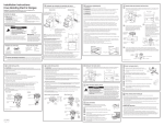
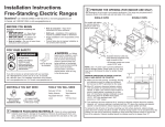
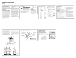
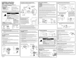
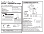
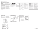
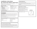
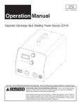
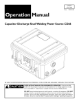
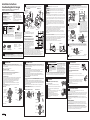
Installation Instructions
Free-Standing Electric Ranges
2 PREPARE THE OPENING (FOR INDOOR USE ONLY)
SINGLE OVEN
Questions? Call 1.800.GE.CARES (1.800.432.2737) or visit www.GEAppliances.com
In Canada, call 1.800.561.3344 or visit www.GEAppliances.ca
BEFORE YOU BEGIN
Read these instructions completely and
carefully.
• ,03257$17³ Save these instructions
for local inspector’s use.
• ,03257$17³ Observe all
governing codes and ordinances.
• Note to Installer – Be sure to leave these
instructions with consumer.
• Note to consumer – Keep these
instructions for future reference.
• Skill level – Installation of this appliance
requires a qualified installer or electrician.
• Proper installation is the responsibility of the
installer.
• Product failure due to improper installation is
not covered under warranty.
On models with baking
or warming drawers,
electrical outlet must not
be in this area.
21ø2”
3ø”
30”
23 ø
31ø4”
21ø2”
297ø8”
297ø8”
141ø2”
47”
47”
FOR YOUR SAFETY:
71ø2”
•
•
•
•
•
Squeeze Connector
(For Conduit
Installations Only)
(UL Listed 40 AMP)
4-Wire Cord 4’ long OR
3-Wire Cord 4’ long
253ø8”
45”
475ø8” Acceptable electrical outlet area.
Orient electrical receptacle so the
length is parallel to floor.
WARNING³ Before beginning
the installation, switch power off at service
panel and lock the service disconnecting
means to prevent power from being
switched on accidentally. When the service
disconnecting means cannot be locked,
securely fasten a prominent warning device,
such as a tag, to the service panel.
TOOLS YOU WILL NEED
Drill with 1/8” Bit
Safety Glasses
Adjustable Wrench
Level
Tin Snips
Tape Measure
Pliers
1/4” Nut Driver
1 REMOVE PACKAGING MATERIALS: Failure to remove packaging materials could
NOTE: Use a 4’ power cord to prevent interference
with the storage drawer. Power cords 41ø2’ to 6’ long
may have to be dressed to allow for proper drawer
closing.
MINIMUM DIMENSIONS BETWEEN COOKTOP,
WALLS AND ABOVE THE COOKTOP:
A. Make sure the wall covering, countertop, flooring
and cabinets around the range can withstand the
heat (up to 200°F) generated by the range.
B. Allow 30” minimum clearance between surface
units and bottom of unprotected wood or metal
cabinet, or allow a 24” minimum when bottom
of wood or metal cabinet is protected by no less
than 1/4” thick flame retardant millboard covered
with not less than No 28 MSG sheet metal, (.015”),
.015” thick stainless steel, .024”
aluminum or .020” copper.
B
C
Both
Sides
NOTE C
Effective January 1, 1996, the National Electrical Code requires that new construction (not
existing) utilize a 4-conductor connection to an electric range. When installing an electric range
in new construction, mobile home, recreational vehicle, or an area where local codes prohibit
grounding through the neutral conductor, refer to the section on four-conductor branch circuit
connections.
This appliance must be supplied with the proper voltage and frequency, and connected to an
individual, properly grounded, 40 amp (minimum) branch circuit protected by a circuit breaker
or time-delay fuse.
Use only a 3-conductor or a 4-conductor UL-listed range cord. These cords may be provided with ring
terminals on wire and a strain relief device.
A range cord rated at 40 amps with 125/250 minimum volt range is required. A 50 amp range cord
is not recommended but if used, it should be marked for use with nominal 13ø8” diameter connection
openings. Care should be taken to center the cable and strain relief within the
knockout hole to keep the edge from damaging the cable.
The neutral or ground wire of the power cord must be connected
to the neutral terminal located in the center of the terminal block and the ground strap must connect the
neutral terminal to the ground plate. The power leads must be connected to the lower left and the lower right
terminals of the terminal block.
DO NOT remove the ground strap connection.
FOR POWER CORD INSTALLATION
A. Remove the 3 lower terminal screws from the terminal block.
B. Insert the 3 terminal screws through each power cord terminal ring and into the lower
terminals of the terminal block. Be certain that the center wire (white/neutral)
is connected to the center lower position of the terminal block.
C. Tighten screws securely into the terminal block.
FOR CONDUIT INSTALLATION
A. Loosen the 3 lower terminal screws on the terminal block. Strip wire to exposed tip about 5/8” long.
B. Insert the center (white/neutral) wire tip through the bottom center terminal block opening.
On certain models, the wire will need to be inserted through the ground strap opening
and then into the bottom center block opening. Insert the two side bare wire tips into
the lower left and the lower right terminal block openings.
C. Tighten the screws until the wire is firmly secured (35 to 50 inch-lbs.). Do not over-tighten
the screws.
NOTE: ALUMINUM WIRING: Aluminum building wire may be used but it must be rated
for the correct amperage and voltage.
Power Cord
Terminal block
(appearance
may vary)
Neutral terminal
Conduit
SINGLE OVEN
C. This appliance has been approved for 0” spacing to adjacent surfaces above the cooktop. However,
a 6” minimum spacing to surfaces less than 15” above the cooktop and adjacent
cabinet is recommended to reduce exposure to steam, grease splatter and heat.
To reduce the risk of burns or fire when reaching over hot surface elements, cabinet storage space
above the cooktop should be avoided. If cabinet storage space is to be provided above
the cooktop, the risk can be reduced by installing a range hood that projects at least 5” beyond
the front of the cabinets. Cabinets installed above the cooktop must be no deeper than 16”.
WARNING: The neutral wire of the supply circuit must be connected to the neutral terminal
located in the lower center of the terminal block. The power leads must be connected to the lower left and the
lower right terminals of the terminal block. The grounding lead must be connected to the frame of the range with
the ground plate and the green ground screw.
FOR POWER CORD INSTALLATION
A. Remove the 3 lower terminal screws from the terminal block. Remove the ground screw and ground
plate and retain them. Cut and discard the ground strap. DO NOT DISCARD ANY SCREWS.
B. Insert the one ground screw into the power cord ground wire terminal ring, through the ground plate
and into the frame of the range.
C. Insert the 3 terminal screws (removed earlier) through each power cord terminal ring and into the lower
terminals of the terminal block. Be certain that the center wire (white/neutral) is connected to the center lower
position of the terminal block. Tighten screws securely into the terminal block.
FOR CONDUIT INSTALLATION
A. Loosen the 3 lower terminal screws on the terminal block. Remove the ground screw and ground plate and
retain them. Cut and discard the ground strap. DO NOT DISCARD ANY SCREWS. Strip wire to exposed tip
about 5/8” long.
B. Insert the ground bare wire tip between the range frame and the ground plate (removed earlier)
and secure it in place with the ground screw (removed earlier). Insert the bare wire (white/neutral) tip through
the bottom center of the terminal block opening. Insert the two side bare wire tips into the lower left and the
lower right terminal block openings.
C. Tighten the screws until the wire is firmly secured (35 to 50 inch-lbs.). Do not over-tighten the screws.
NOTE: ALUMINUM WIRING: Aluminum building wire may be used but it must be rated
for the correct amperage and voltage.
Wire tips
Terminal
block
After–Power Cord
Ground strap
Ground
strap
Conduit
or
Neutral
terminal
Terminal
block
Neutral
terminal
Ground plate
(grounding to
range)
Ground
screw
After–Conduit
PROCEED TO STEP 7.
Terminal
block
Wire
tips
Ground screw
08-15 GE
For power cord installations only (see the
next step if using conduit), assemble the
strain relief in the hole. Insert the power
cord through the strain relief and tighten.
Allow enough slack to easily attach the
cord terminals to the terminal block. If tabs
are present at the end of the winged strain
relief, they can be removed for better fit.
NOTE: Do not install the power cord without
a strain relief. The strain relief bracket MUST
be installed before reinstalling the rear range
wiring cover.
Strain relief
Knockout
ring in
bracket
Terminal
block
Knockout ring
removed
Bracket
Rating plate
For 3/4” conduit installations only, purchase a squeeze connector matching the diameter of your
conduit and assemble it in the hole. Insert the conduit through the squeeze connector and tighten.
Allow enough slack to easily attach the wires to the terminal block. NOTE: Do not install the conduit
without a squeeze connector. The squeeze connector MUST be installed before reinstalling the rear
range wiring cover.
Squeeze
connector
Rating plate
Conduit
E
Terminal block
Bracket
Replace wire cover on range back by sliding its left edge under the retaining tabs and replace the
screws removed earlier. Make sure that no wires are pinched between cover and range back.
To reduce the risk of tipping the range, the
range must be secured by a properly installed
WARNING
anti-tip bracket. See installation instructions
Tip-Over Hazard
shipped with the bracket for complete details
• A child or adult can tip the range and be killed.
before attempting to install.
• Install the anti-tip bracket to the wall or floor.
• Engage the range to the anti-tip bracket by sliding the To check if the bracket is installed and
range back such that the foot is engaged.
engaged properly, look underneath the range
• Re-engage the anti-tip bracket if the range is moved.
to see that the rear leveling leg is engaged
• Failure to do so can result in death or serious burns
in the bracket. On some models, the storage
to children or adults.
drawer or kick panel can be removed for
easier inspection. If visual inspection is not
possible, slide the range forward, confirm the anti-tip bracket is securely attached to the floor or wall, and
slide the range back so the leveling leg is under the anti-tip bracket. If the range is pulled from the wall for
any reason, always repeat this procedure to verify the range is properly secured by the anti-tip bracket.
Never completely remove the leveling legs or the range will not be secured to the anti-tip bracket.
8 LEVEL THE RANGE
WARNING: Never completely remove the leveling leg
8 LEVEL THE RANGE (CONT.)
G
Position cord so that it does not interfere with drawer.
Place drawer rail on guides. Push the drawer in until it stops.
H
Lift front of drawer and push in until the stops clear
the guides.
I
Lower the front of the drawer and push in until it closes.
A
Plug in unit and slide into place. Pull drawer out until it stops.
B
Lift front of drawer until the stops clear the guide. Remove the drawer.
C
Install the oven shelves in the oven and position the range where
it will be installed.
D
Check for levelness by placing a spirit level on one of the oven shelves. Spirit level
7DNHWZRUHDGLQJV³ZLWKWKHOHYHOSODFHGGLDJRQDOO\ILUVW
in one direction and then the other.
E
The front leveling legs can be adjusted from the bottom
and the rear legs can be adjusted from the top or the bottom.
Use an adjustable wrench to adjust the leveling legs until
the range is level.
F
Stop
Leg
leveler
MODELS WITH WARMING DRAWERS OR DOUBLE OVEN
Raise
range
A
Plug in the unit.
B
Measure the height of your countertop at the rear of the opening (X).
C
Adjust two rear leveling legs so that the rear of cooktop is at the same height
as the counter (Y).
D
Slide unit into place.
E
Install oven shelves in the oven and position the range where it will be installed.
F
Check for levelness by placing a spirit level on one of the oven shelves.
7DNHWZRUHDGLQJV³ZLWKWKHOHYHOSODFHGGLDJRQDOO\ILUVWLQRQHGLUHFWLRQ
and then the other.
G
Adjust front leveling legs until the range is level.
as the range will not be secured to the anti-tip device properly.
MODELS WITH STORAGE DRAWER
Lower
range
X
Y
9 FINAL INSTALLATION CHECKLIST
• Check to make sure the circuit breaker is closed (RESET) or the circuit fuses are replaced.
• Be sure power is in service to the building.
• Check that all packing materials and tape have been removed. This will include tape on metal panel under
control knobs (if applicable), adhesive tape, wire ties, cardboard and protective plastic. Failure to remove
these materials could result in damage to the appliance once the appliance has been turned on and
surfaces have heated.
• Check that the door and drawer are parallel to each other and that both operate smoothly. If they
do not, see the Owner’s Manual for proper replacement.
• Check to make sure that the rear leveling leg is fully inserted into the Anti-Tip bracket and that the bracket
is securely installed.
OPERATION CHECKLIST
Power cord
31-10816-2
Terminal block
(appearance
may vary)
D
DOUBLE OVEN
7 ANTI-TIP DEVICE INSTALLATION
Before–Power Cord and Conduit
Ground
plate
C
For power cord and 1” conduit only, remove the
knockout ring (13ø8”) located on bracket directly
below the terminal block. To remove the
knockout, use a pair of pliers to bend the
knockout ring away from the bracket and
twist until ring is removed.
Proceed to step 5 or 6.
Terminal
block
Ground strap
B
Terminal block cover
Power cord
6 4-WIRE INSTALLATION
WARNING:
Screw to
remove
terminal
block cover
Wire cover
A
result in damage to the appliance. Remove all packing parts from oven, racks, heating elements
and drawer. Also, remove protective film and labels on the outer door, cooktop and control panel.
5 3-WIRE INSTALLATION
5 screws to
remove wire
cover
Retaining
tabs
You must use a single-phase, 120/208 VAC or 120/240 VAC, 60 hertz electrical system. If you connect
to aluminum wiring, properly installed connectors approved for use with aluminum wiring must be
used.
The rating plate is located on the oven frame or on the side of the drawer frame.
A
Remove wire cover (on the back of range) by removing screws using a 1/4” nut driver. You can
access the terminal block by either removing a terminal block cover (on some models) or the
wire cover. Do not discard these screws.
Back of range
Back of range
To prevent shock, remove house fuse or open circuit breaker before
beginning installation.
Check with your local utilities for electrical codes which apply in your area. Failure to wire your oven
according to governing codes could result in a hazardous condition. If there are no local codes, your
oven must be wired and fused to meet the National Electrical Code, NFPA No.
70 – latest edition, available from the National Fire Protection Association.
Anti-Tip Bracket
Kit Included
If you did not receive an anti-tip bracket with your purchase,
call 1.800.626.8774 to receive one at no cost. (In Canada,
call 1.800.561.3344.) For installation instructions of the bracket,
visit: www.GEAppliances.com. (In Canada, www.GEAppliances.ca.)
MATERIALS YOU MAY NEED
73ø4”
3”
36”
253ø8”
WARNING
To prevent fire or shock, do not use an extension cord with this appliance.
We recommend you have the electrical wiring and hookup of your range connected by a qualified
electrician. After installation, have the electrician show you how to disconnect power from the range.
*
*
7”
WARNING:
WARNING:
1 2”
25”
A
local codes do not allow grounding through neutral, require a 4-conductor UL-listed range cord.
30”
14
4 POWER CORD AND CONDUIT INSTALLATION
WARNING: This appliance must be properly grounded.
WARNING: All new constructions, mobile homes, recreational vehicles and installations where
DOUBLE OVEN
4”
Tip-Over Hazard
A child or adult can tip the range and be killed.
Install the anti-tip bracket to the wall or floor.
Engage the range to the anti-tip bracket by sliding the
range back such that the foot is engaged.
Re-engage the anti-tip bracket if the range is moved.
Failure to do so can result in death or serious burns
to children or adults.
3 ELECTRICAL REQUIREMENTS
See illustrations for all rough-in and spacing dimensions. The range may be placed with 0”
clearance (flush) at the back wall and side walls of the cabinet.
Ground
plate
(grounding
to range)
• Turn on one of the surface units to observe that the element glows within 60 seconds. Turn the unit
off when glow is detected. If the glow is not detected within the time limit, recheck the range wiring
connections. If change is required, retest again. If no change is required, have building wiring checked for
proper connections and voltage.
• Check that the Clock (on models so equipped) display is energized. If a series of horizontal red
lines appear in the display, disconnect power immediately. Recheck the range wiring connections.
If change is made to connections, retest again. If no change is required, have building wiring checked for
proper connections and voltage. It is recommended that the clock be changed if the red lines appear.
• Be sure all range controls are in the OFF position before leaving the range.
Instrucciones de instalación
Cocinas eléctricas independientes
¿Preguntas? Llamada 1.800.GE.CARES (1.800.432.2737) o visita www.GEAppliances.com
En Canadá, llame 1.800.561.3344 o visita www.GEAppliances.ca
ANTES DE COMENZAR
Lea estas instrucciones por completo y con
detenimiento.
• ,03257$17(³Guarde estas
instrucciones para el uso de inspectores
locales.
• ,03257$17(³ Siga todos los códigos
y ordenanzas vigentes.
• Nota al instalador – Asegúrese de dejar estas
instrucciones con el consumidor.
• Nota al consumidor – Conserve estas
instrucciones para referencia futura.
• Nivel de destreza – La instalación de este
aparato debe efectuarla un instalador o
electricista calificado.
• El instalador tiene la responsabilidad de
efectuar una instalación adecuada.
• La garantía no cubre las fallas del producto
debido a una instalación incorrecta.
2
31ø4”
•
•
Si no recibió un soporte anti volcaduras con su compra,
llame al 1.800.626.8774 para recibir uno sin costo.
(En Canadá, llame al 1.800.561.3344). Para recibir
instrucciones de instalación del soporte, visite:
GEAppliances.com (En Canadá, GEAppliances.ca.).
MATERIALES QUE PUEDE NECESITAR
Conector de presión
(Sólo para instalaciones
con conductos
portacables)
7”
297ø8”
Kit de soporte
anti-volcaduras incluido
ADVERTENCIA³ Antes
de comenzar la instalación, apague el
encendido en el panel de servicio y bloquee
el medio de desconexión del servicio a fin de
evitar que el encendido se active de forma
accidental. Cuando el medio de desconexión
del servicio no se pueda bloquear, ajuste
de manera segura un ítem de advertencia
que esté bien visible, tal como una etiqueta,
sobre el panel de servicio.
HERRAMIENTAS NECESARIAS
(Aprobados por UL de 40 AMP)
Cable de 4 alambres de 4’
de largo O Cable de 3 alambres
de 4’ de largo
Perforadora con
broca de 1/8”
Tijeras para
hojalata
Gafas de
seguridad
Cinta métrica
Llave ajustable
Llave de tuercas
de 1/4”
Nivel
Alicates
47”
71ø2”
PARA INSTALACIÓN DE CABLE DE ENERGÍA
A. Quite los 3 tornillos inferiores del bloque terminal.
B. Introduzca los 3 tornillos de terminal a través de cada anillo de terminal de cable de energía y
dentro de las terminales inferiores del bloque terminal. Asegúrese de que el alambre central (blanco/
neutral) se encuentre conectado a la posición central inferior del bloque terminal.
C. Ajuste bien los tornillos al bloque terminal.
PARA INSTALACIÓN DE CONDUCTO PORTACABLES
A. Afloje los 3 tornillos inferiores del bloque terminal. Pele el cable de la punta expuesta con una
longitud de 5/8”.
B. Introduzca la punta del cable central (blanco/neutral) a través de la abertura del bloque terminal
central inferior. En algunos modelos, el cable tendrá que introducirse a través de la abertura de la cinta de
conexión a tierra y luego a través de la abertura del bloque central inferior. Introduzca las dos puntas de
cable pelado dentro de las aberturas de bloque terminal izquierda inferior y derecha inferior.
C. Ajuste los tornillos hasta que el cable quede bien firme (35 a 50 pulg-lbs). No ajuste los tornillos de más.
NOTA: CABLEADO DE ALUMINIO: Puede utilizarse cable de construcción de aluminio pero debe clasificarse
para el amperaje y voltaje correctos.
Placa de
conexión a
tierra
Cable de energía
SIGA CON EL PASO 7.
36”
Área aceptable para tomacorriente.
Oriente el tomacorriente para que
la longitud sea paralela al piso.
Conducto portacables
Puntas de
los cables
Vigente desde el 1 de enero de 1996, el Código Eléctrico Nacional requiere que las nuevas
construcciones (no existentes) utilicen una conexión de cuatro conductores a una cocina eléctrica. Cuando
instale una cocina eléctrica en una nueva construcción, una casa rodante, un vehículo
recreativo o un área donde los códigos locales prohíben la conexión a tierra a través de un conductor
neutral, consulte la sección sobre conexiones en circuito derivado de cuatro conductores.
Consulte a las empresas de servicio público sobre los códigos eléctricos que se aplican en su área. No
realizar el cableado de su horno de acuerdo con los códigos vigentes puede provocar una situación
peligrosa. Si no existen códigos locales, su cocina debe contar con cables y fusibles que cumplan con los
requisitos del Código Eléctrico Nacional, ANSI/NFPA No. 70–Última edición.
Este electrodoméstico debe recibir el voltaje y frecuencia adecuados, y debe conectarse a un circuito
derivado individual con adecuada conexión a tierra de 40 amperios (mínimo) protegido por un
interruptor de circuitos o fusible con retraso.
Utilice sólo un cable para cocinas de 3 o 4 conductores aprobado por UL. Estos cables pueden contar con
terminales de anillo en alambre y un dispositivo de alivio de tensión.
Se requiere un cable para cocinas clasificado para 40 amperios con rango de voltios mínimo de 125/250.
No se recomienda un cable de 50 amperios, pero si se utiliza, debe señalizarse para usarse con aberturas
de conexión de un diámetro nominal de 1-3/8”. Debe tenerse cuidado al centrar el cable y el alivio de
tensión dentro del orificio de expulsión para evitar que el borde dañe el cable.
PARA INSTALACIÓN DE CONDUCTO PORTACABLES
A. Afloje los tres tornillos inferiores del bloque terminal. Quite el tornillo a tierra y la placa de conexión a tierra y
consérvelos. Corte y descarte la cinta de conexión a tierra. NO ELIMINE NINGÚN TORNILLO.
B. Introduzca la punta pelada del cable a tierra entre el marco de la cocina y la placa de conexión a tierra
(quitada antes) y asegúrela en su lugar con el tornillo de conexión a tierra (quitado antes). Introduzca la punta
pelada del cable (blanco/neutral) a través del centro inferior de la abertura del bloque terminal. Introduzca las dos
puntas de cable pelado dentro de las aberturas de bloque terminal izquierda inferior y derecha inferior.
C. Ajuste los tornillos hasta que el cable quede bien firme (35 a 50 pulg-lbs). No ajuste los tornillos de más.
NOTA: CABLEADO DE ALUMINIO: Puede utilizarse cable de construcción de aluminio pero debe clasificarse
para el amperaje y voltaje correctos para poder realizar la conexión.
Después–Cable de energía
Cinta de
conexión a tierra
Bloque
terminal
Bloque
terminal
o
Terminal
neutral
Terminal
neutral
Placa de
conexión a tierra
(conexión a tierra
de la cocina)
Tornillo de
conexión
a tierra
Después–Conducto portacables
Bloque
terminal
Quite la tapa del cable (en la parte trasera de la cocina) quitando tornillos mediante una llave
de tuercas de 1/4”. Usted puede acceder el bloque terminal quitando la tapa del bloque
terminal (en algunos modelos) o la tapa de los cables. No elimine esos tornillos.
Parte trasera de la cocina
Parte trasera de la cocina
Placa de
conexión
a tierra
(conexión a
tierra de la
cocina)
5 tornillos
para
quitar la
tapa del
cable
Tornillo
para quitar
la tapa
del bloque
terminal
Tapa de los cables
B
HORNO SIMPLE
Para cable de energía y pasacables de 1”
solamente, quite el anillo de expulsión (1-3/8”)
ubicado en el soporte directamente debajo del
bloque terminal. Para quitar el anillo, utilice un
par de alicates para doblar el anillo de expulsión
lejos del soporte y gire hasta remover el anillo.
Bloque terminal
(la apariencia
puede cambiar)
Anillo de
expulsión
en el
soporte
D
HORNO DOBLE
Tapa del bloque terminal
C
Sólo para instalaciones de cable de energía (ver el
paso siguiente si utiliza un conducto portacables),
instale el alivio de tensión en el orificio. Introduzca el
cable de energía a través del alivio de tensión y ajuste.
Deje un largo suficiente para poder conectar las
terminales de cable al bloque terminal. Si hay
lengüetas al final del alivio de tensión con alas, éstas
pueden quitarse para un ajuste mejor.
NOTA: No instale el cable de energía sin un alivio de
tensión. El soporte del alivio de tensión DEBE instalarse
antes de volver a colocar la tapa del cableado trasero
de la cocina.
Alivio de tensión
Bloque
terminal
Anillo de
expulsión
quitado
La placa de clasificación se encuentra ubicada sobre el cajón de almacenamiento en el marco del horno o
en el lado del marco del cajón.
Placa de
clasificación
Sólo para instalaciones con conducto portacables de 3/4”, adquiera un conector de presión que se
ajuste al diámetro de su conducto e instálelo en el orificio. Introduzca el conducto a través del
conector de presión y ajuste. Deje un largo suficiente para poder pegar los cables al bloque terminal.
NOTA: No instale el conducto sin un conector de presión. El conector de presión DEBE instalarse
antes de volver a colocar la tapa del cableado trasero de la cocina.
Conector
de presión
Placa de
clasificación
E
Soporte
Cable de
energía
Conducto
portacables
Bloque terminal
Soporte
Reemplace la tapa de los cables de la cocina deslizando el lado izquierdo bajo las lengüetas de
retención y reemplazando los cinco tornillos quitados anteriormente. Verifique que los cables
no hayan sufrido pellizcos entre la tapa y la parte trasera de la cocina.
SIGA CON EL PASO 5 O 6.
ADVERTENCIA
PARA INSTALACIÓN DE CABLE DE ENERGÍA
A. Quite los 3 tornillos inferiores del bloque terminal. Quite el tornillo a tierra y la placa de conexión a tierra y
consérvelos. Corte y descarte la cinta de conexión a tierra. NO ELIMINE NINGÚN TORNILLO.
B. Introduzca el tornillo de conexión a tierra dentro del anillo terminal de conexión a tierra del cable de
energía, a través de la placa de conexión a tierra y dentro del marco de la cocina.
C. Introduzca los 3 tornillos de terminal (quitados antes) a través de cada anillo de terminal de cable de
energía y dentro de las terminales inferiores del bloque terminal. Asegúrese de que el alambre central
(blanco/neutral) se encuentre conectado a la posición central inferior del bloque terminal. Ajuste bien los
tornillos al bloque terminal.
Cinta de
conexión
a tierra
Conducto
portacables
Usted debe usar un sistema eléctrico de 60 hercios CA de fase única de 120/280 voltios o 120/240 voltios. Si
tiene una conexión con cableado de aluminio, deben utilizarse conectores adecuadamente instalados para
utilizar con cableado de aluminio.
Si el servicio eléctrico provisto no cumple con las especificaciones anteriores, haga que un electricista con
licencia instale un tomacorriente aprobado.
terminal neutral ubicada en el centro inferior del bloque terminal. Los cables de energía deben estar conectados a
las terminales inferior izquierda e inferior derecha del bloque terminal. El cuarto cable a tierra debe estar conectado al
marco de la cocina con la placa de conexión a tierra y el tornillo a tierra.
Bloque
terminal
A
Recomendamos que un electricista calificado conecte el cableado eléctrico y su cocina. Después
de la instalación, solicite al electricista que le indique cómo desconectar la energía de la cocina.
ADVERTENCIA: El cable neutral del circuito de suministro debe estar conectado a la
Antes–Cable de energía
y conducto portacables
INSTALACIÓN DE CABLE DE ENERGÍA Y DE PASACABLES
Lengüetas
de
retención
7 INSTALACIÓN DE DISPOSITIVO ANTI-VOLCADURAS
Tornillo de
conexión
a tierra
08-15 GE
45”
NOTA: Utilice un cable de energía de 4’ para evitar una
interferencia con el cajón de almacenamiento. Los cables de
energía de 41ø2’ a 6’ de largo pueden tener que cubrirse para
**30” Min.
poder cerrar el cajón correctamente.
***6”
Min.
DIMENSIONES MÍNIMAS ENTRE LA ESTUFA, LAS PAREDES Y
**15” Min.
SOBRE LA PARTE SUPERIOR DE LA
ESTUFA:
A. Verifique que el revestimiento de las paredes, el
mostrador, el piso y los gabinetes ubicados alrededor de
la cocina puedan soportar el calor (hasta 200°F) generado
por la cocina.
*0”
*0”
B. Deje un espacio de 30” como mínimo entre las unidades
de superficie y la parte inferior de gabinetes de madera o
de metal sin protección o deje un
mínimo de 24” cuando la parte inferior del gabinete
de madera o metal se encuentre protegida por cartón
aislante de un grosor no menor a 1/4” y con retardo de
llama cubierto con una placa de metal no menor a MSG Nº 28, acero inoxidable de un grosor de .015”,
aluminio de .024” o cobre de .020”.
C. Este aparato ha sido aprobado para un espacio de 0” respecto de superficies adyacentes sobre la estufa.
Sin embargo, se recomienda un espacio mínimo de 6” respecto de superficies menores a 15” sobre la
estufa y gabinete adyacente para reducir la exposición al vapor, salpicaduras de grasa y calor.
Para reducir el riesgo de quemaduras o incendios cuando se incline sobre los elementos de superficie calientes,
debe evitarse la instalación de espacios de almacenamiento en gabinetes sobre la estufa. Si debe contarse con
espacio para almacenamiento en gabinetes sobre la estufa, puede reducirse el riesgo instalando una campana
de cocina que sobresalga por lo menos 5” más allá del frente de los gabinetes. Los gabinetes instalados por
encima de la estufa no deben tener una profundidad mayor a los 16”.
Puntas de
los cables
31-10816-2
73ø4”
3”
6 INSTALACIÓN DE 4 ALAMBRES
ADVERTENCIA: El cable neutral o a tierra del cable de energía debe estar
conectado a la terminal neutral ubicada en el centro del bloque terminal y la cinta de
conexión a tierra debe conectar la terminal neutral a la placa de conexión a tierra. Los cables de energía
deben estar conectados a las terminales inferior izquierda e inferior derecha del bloque terminal.
NO QUITE la cinta de conexión a tierra.
Cinta de
conexión a tierra
297ø8”
141ø2”
ADVERTENCIA: Para prevenir un incendio o descarga eléctrica, no utilice un cable
de extensión con este aparato.
ADVERTENCIA: Para prevenir una descarga eléctrica, quite el fusible o abra
el interruptor de circuitos antes de comenzar la instalación.
253ø8”
475ø8”
5 INSTALACIÓN DE TRES (3) ALAMBRES
Terminal neutral
*
253ø8”
provocar daños al electrodoméstico. Quite todas las partes de empaque del horno, bandejas,
elementos calentadores y cajón. También, quite la película protectora y las
etiquetas de la puerta exterior, estufa y panel de control.
Bloque terminal
(la apariencia
puede cambiar)
2ø”
4”
1 QUITE LOS MATERIALES DE ENVÍO: No quitar los materiales de empaque puede
Cable de energía
31ø4”
*
PARA SU SEGURIDAD
•
•
•
231ø2”
12
4
ADVERTENCIA: Todas las construcciones nuevas, casas rodantes, vehículos recreativos e
instalaciones donde los códigos locales no permiten una conexión a tierra a través de un neutral requieren
un cable para cocina de 4 conductores aprobado por UL.
30”
30”
25”
ADVERTENCIA
ADVERTENCIA: Esta unidad debe contar con una adecuada conexión a tierra.
HORNO DOBLE
HORNO SIMPLE
En los modelos con cajones de 1
horneado o calentadores, el 2 ø2”
tomacorriente no debe
hallarse en esta área.
47”
Riesgo de Caída
Un niño o adulto pueden volcar la cocina y morir.
Instale el soporte anti-volcaduras sobre la pared o el piso.
Asegúrese la estufa al soporte anti-volcaduras deslizando
la unidad hacia atras de tal manera que la pata niveladora
sea enganchada.
Vuelva a adherir el soporte anti-volcaduras si la estufa
se mueve de lugar.
Si esto no se hace, se podrá producir la muerte o
quemaduras graves en niños o adultos.
3 REQUERIMIENTOS ELÉCTRICOS
CÓMO PREPARAR LA ABERTURA (PARA USO EN EL INTERIOR SOLAMENTE)
Ver ilustraciones con todas las dimensiones de empotrado y de espacio. La cocina puede ubicarse
con un espacio de 0” (alineado) sobre la pared trasera y las paredes laterales del gabinete.
Riesgo de Caída
• Un niño o adulto pueden volcar la cocina y morir.
• Instale el soporte anti-volcaduras sobre la pared o el piso.
• Asegúrese la estufa al soporte anti-volcaduras deslizando
la unidad hacia atras de tal manera que la pata niveladora
sea enganchada.
• Vuelva a adherir el soporte anti-volcaduras si la estufa
se mueve de lugar.
• Si esto no se hace, se podrá producir la muerte o
quemaduras graves en niños o adultos.
A fin de reducir el riesgo de inclinar la cocina,
ésta deberá estar asegurada con un soporte anti
volcaduras. Lea las instrucciones de instalación
que se enviaron con el soporte para obtener un
detalle completo antes de comenzar la instalación.
A fin de controlar que el soporte esté instalado
y adosado correctamente, retire el cajón de
almacenaje o la parte inferior delantera y observe
debajo de la cocina que la pata niveladora esté
adosada al soporte. En modelos que no poseen
un cajón de almacenaje o parte inferior delantera,
incline con cuidado la cocina hacia adelante.
El soporte debería detener la cocina dentro de las cuatro pulgadas. De no ser así, el soporte deberá ser instalado
nuevamente. Si la cocina es expulsada de la pared por alguna razón, siempre repita este procedimiento a fin de verificar
que esté asegurado de forma correcta con un soporte anti volcaduras. Nunca elimine completamente las patas
niveladoras, ya que de ser así la cocina no estará adecuadamente asegurada por el dispositivo anti volcaduras.
8 NIVELE LA COCINA (CONT.)
G
H
I
ADVERTENCIA: Nunca quite las patas de nivelación por completo
ya que la cocina no quedará bien sujeta al dispositivo anti-volcaduras.
MODELOS CON CAJONES DE ALMACENAMIENTO
A
B
C
D
E
F
Traba
Enchufe la unidad y deslícela en su lugar. Tire del cajón hacia fuera
hasta que pare.
Nivel de
Levante el frente del cajón hasta que las trabas superen
burbuja de aire
las guías. Retire el cajón.
Instale los estantes del horno en el horno y coloque la cocina
en la ubicación donde se va a instalar.
Controle la nivelación colocando un nivel de burbuja de aire sobre uno
de los estantes del horno. Haga dos lecturas–con el nivel
ubicado en diagonal primero en una dirección y luego en la otra.
Las patas de nivelación frontales pueden ajustarse desde la parte inferior y las patas traseras
pueden ajustarse desde la parte superior o inferior.
Utilice una llave ajustable para ajustar las patas niveladoras hasta que la cocina quede
nivelada.
Nivelador
de patas
Baje el frente del cajón y empuje hacia adentro hasta que cierre.
Levante la
cocina
MODELOS CON CAJONES O CALENTADORES HORNO DOBLE
A
Enchufe la unidad.
B
Mida la altura de su mostrador de encimera en la parte trasera
de la abertura (X).
Ajuste las dos patas de nivelación traseras para que la parte trasera
de la estufa se encuentre a la misma altura del mostrador (Y).
C
8 NIVELE LA COCINA
Coloque el cable de modo que no interfiera con el cajón.
Coloque el riel del cajón en las guías. Empuje el cajón
hacia adentro hasta que pare.
Levante el frente del cajón y empuje hasta que las trabas superen
las guías.
Baje la
cocina
D
Deslice la unidad en su lugar.
E
Instale los estantes del horno en la unidad y coloque la cocina donde se instalará.
F
Controle la nivelación colocando un nivel de burbuja de aire sobre uno de los estantes
del horno. Haga dos lecturas–con el nivel ubicado en diagonal primero en una dirección
y luego en la otra.
G
Ajuste las patas de nivelación frontales hasta que la cocina quede nivelada.
X
Y
9 LISTA DE CONTROL FINAL DE LA INSTALACIÓN
• Verifique que el interruptor de circuitos se encuentre cerrado (RESET) o que los fusibles del circuito se
hayan reemplazado.
• Asegúrese de que se cuente con suministro eléctrico en el edificio.
• Controle que se haya quitado todo el material de empaque y la cinta. Esto incluye cinta sobre
el panel de metal bajo las perillas de control (si corresponde), cinta adhesiva, ataduras de alambre, cartón
y plástico protector. No quitar estos materiales puede provocar daños al electrodoméstico
una vez que el aparato se haya encendido y las superficies se hayan calentado.
• Controle que la puerta y el cajón se encuentren paralelos y que los dos funcionen correctamente.
Si no es así, consulte el Manual del propietario para un reemplazo adecuado.
• Controle que la pata de nivelación trasera esté bien introducida dentro del soporte anti-volcaduras
y que el soporte se encuentre bien instalado.
LISTA DE CONTROL DE FUNCIONAMIENTO
• Accione una de las unidades de superficie para observar que el elemento se encienda dentro de los 60
segundos. Apague la unidad cuando se detecte el encendido. Si no se detecta el encendido dentro del límite
de tiempo, vuelva a verificar las conexiones del cableado de la cocina. Si se requiere un cambio, vuelva a
probar el aparato. Si no se requiere un cambio, haga controlar el cableado del
edificio para verificar conexiones y voltaje adecuados.
• Controle que la pantalla del reloj (en modelos que lo incluyan) reciba energía. Si en la pantalla
aparecen una serie de líneas rojas horizontales, desconecte la energía de inmediato. Vuelva a
controlar las conexiones del cableado de la cocina. Si se efectúa un cambio en las conexiones, vuelva
a probar el aparato. Si no se requiere un cambio, haga controlar el cableado del edificio para verificar
conexiones y voltaje adecuados. Se recomienda cambiar el reloj si aparecen las líneas rojas.
• Asegúrese de que los controles de la cocina se encuentren en la posición OFF (apagado) antes
de alejarse de la cocina.