1
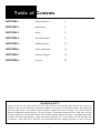
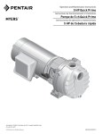
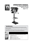
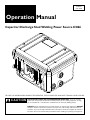
ILM007A
June, 2006
Price
$5.50 USA
Operation Manual
Capacitor Discharge Stud Welding Power Source CD66
BE SURE THIS INFORMATION REACHES THE OPERATOR. EXTRA COPIES ARE AVAILABLE THROUGH YOUR SUPPLIER.
CAUTION
These INSTRUCTIONS are for experienced operators. If you are not fully
familiar with the principles of operation and safe practices for arc welding equipment, we urge
you to read AWS SP - “Safe Practices” available from the American Welding Society.
DO NOT permit untrained persons to install, operate, or maintain this equipment. DO NOT
attempt to install or operate this equipment until you have read and fully understand these instructions. If you do not fully understand these instructions, contact your supplier for further information. Be sure to read the Safety Precautions before installing or operating this equipment.
T a b l e o f Contents
SECTION 1:
Safety Precautions
3
SECTION 2: Specifications
8
SECTION 3:
Set Up
9
SECTION 4:
Normal Operation
11
SECTION 5:
Trouble Shooting
16
SECTION 6:
System Maintenance
18
SECTION 7:
Schematic Diagram
19
SECTION 8:
Parts List
20
WARRANTY
Image warrants that the goods sold will be free from defects in workmanship and material. This warranty is
expressly in lieu of other warranties, expressed or implied or for fitness for a particular purpose. The liability shall
arise only upon return of the defective goods at Buyer’s expense after notice to Image. The warranty shall be
limited to replacement with like goods or, at Image’s option, to refunding the purchase price. Image will not accept
receipt of equipment returned unless buyer has previously afforded Image’s personnel a reasonable opportunity
to inspect and repair said equipment. Image will warrant components for 1 year and labor for 180 days from date
of shipment. Image shall not be liable for any consequential damages including improper set up by customer.
Safety Precautions
Section 1
U S E R S RESPONSIBILITY
This equipment will perform in conformity with the description contained in this manual and accompanying labels and/or
inserts when installed, maintained and repaired in accordance with the instructions provided. This equipment must be checked
periodically. Defective equipment should not be used. Parts that are broken, missing, worn, distorted or contaminated
should be replaced immediately. Should such repair or replacement become necessary, the manufacturer recommends
that a telephone or written request for service advice be made to the Authorized Distributor from whom purchased.
This equipment or any of it’s parts should not be altered without the prior written approval of the manufacturer. The
user of this equipment shall have the sole responsibility for any malfunction which results from improper use, faulty maintenance, damage, improper repair or alteration by anyone other than the manufacturer or a service facility designated by
the manufacturer.
This symbol appearing throughout this manual means
A TTENTION! BE ALERT!
Your safety is involved.
The following definitions apply to DANGER, WARNING, CAUTION
found throughout this manual.
DANGER
Used to call attention to immediate hazards which, if not avoided, will result in
immediate, serious personal injury or loss
of life.
WARNING
Used to call attention to potential hazards
which could result in personal injury or lost
of life.
CAUTION
Used to call attention to hazards which
could result in minor personal injury.
WARNING: These Safety Precautions are for your protection.
They summarize precautionary information from the references
listed in the Additional Safety Information section. Before
performing any installation or operating procedures, be sure to
read and follow the safety precautions listed below as well as all
other manuals, material safety data sheets, labels, etc. Failure to
observe Safety Precautions can result in injury or death.
Safety Precautions
Section 1
ARC RAYS CAN BURN EYES AND SKIN The arc, like the sun, emits ultraviolet and infrared (visible and
in-visible) and other radiation and can injure skin and eyes.
Sparks and hot metal can fly off the weld. Training in the proper
use of the processes and equipment is essential to prevent accidents. Therefore:
1)
2)
3)
3)
4)
6)
ELECTRICAL SHOCK Contact with live electrical parts and ground can cause severe
injury or death. The electrode (the weld stud and chuck) and
work circuit (ground) are electrically live whenever the output
is on. The input power circuit and the machine internal circuits
are also live whenever power is on. Improperly installed or
improperly grounded equipment is a hazard.
Always wear safety glasses with side shields in any work area, even if wearing a
welding helmet, face shields and goggles are also required.
Always use a face shield fitted with the correct shade of filter to protect your
face and eyes when welding or watching (See ANSI Z49.1 and Z87.1 listed
in Safety Standards). Cover sparks and rays of the arc when operating or
observing operations.
Use protective non-flammable screens or barriers to protect others from
flash and glare. Warn bystanders not to watch the arc and not to expose
themselves to the rays of the electric-arc or hot metal.
Wear flameproof gauntlet type gloves, heavy long-sleeve shirt, cuffless trousers, high topped shoes, and a welding helmet or cap for hair protection, to
protect against arc rays and hot sparks or hot metal. A flameproof apron may
also be desirable as protection against radiated heat and sparks.
Hot sparks or metal can lodge in rolled up sleeves, trousers cuffs or pockets.
Sleeves and collars should be kept buttoned, and open pockets eliminated
from the front of clothing.
Use goggles over safety glasses when chipping slag or grinding. Chipped slag
may be hot and can fly far. Bystanders should also wear goggles over safety
glasses.
1)
2)
3)
4)
5)
6)
7)
8)
9)
ELECT R I C A N D M A G N E T I C F I E L D S Electric and Magnetic Fields may be dangerous. Electric current
flowing through any conductor causes localized Electric and
Magnetic Fields (EMF). Welding and cutting current creates EMF
around welding cables and welding machines.
Therefore:
1)
2)
3)
10)
11)
12)
Welders having pacemakers should consult their physician before welding.
EMF may interfere with some pacemakers.
Exposure to EMF may have other health effects which are unknown.
Welders should use the following procedures to minimize exposure to EMF:
A) Route the electrode and work cables together. Secure them with tape
when possible.
B) Never coil the torch or work cable around your body.
C) Do not place your body between the torch and work cables. Route
cables on the same side of your body.
D) Connect the work cable to the work piece as close as possible to the
area being welded.
E) Keep welding power source and cables as far away from your body as
possible.
13)
14)
15)
16)
17)
18)
19)
20)
21)
22)
FLYING METAL CAN INJURE EYES 1) Welding, chipping, wire brushing and grinding can cause sparks and flying metal. As welds cool, they can throw
off slag.
2) Wear approved safety glasses with side shields even under your welding helmet.
23)
Disconnect input power before installing or servicing this equipment. Lockout/tagout input power according to OSHA 29 CFR 1910.147 (see Safety
Standards).
Do not touch live electrical parts. Do not touch the electrode (stud) if you
are in contact with the work, ground, or another electrode from a different
machine.
Be sure the power source frame (chassis) is connected to the ground system
of the input power.
When making input connections, attach proper grounding conductors first and
then double-check connections.
Always verify the supply ground - check and be sure that input power cord
ground wire is properly connected to ground terminal in disconnect box or
that cord plug is connected to a properly grounded receptacle outlet.
Refer to ANSI/ASC Standard Z49.1 (listed on page 6) for specific grounding
recommendations. Do not mistake the work lead for a ground cable.
Clamp work cable with good metal-to-metal contact (spring and/or magnetic
clamps are not recommended) to work piece as near the weld as practical.
DO NOT use welding current in damp areas, if movement is confined, or if
there is danger of falling.
Properly install and ground this equipment according to this Owner’s Manual
and national, state and local codes.
Connect the work cable to the work piece. A poor or missing connection can
expose you or others to a fatal shock.
Keep everything dry, including clothing, work area, cables, torch/electrode
holder and power source.
Wear dry, hole-free insulated gloves & body protection before turning on
power.
Insulate yourself from work and ground using dry insulating mats or covers big
enough to prevent any physical contact with the work or ground.
Don’t stand directly on metal or the earth while working in tight quarters or a
damp area; stand on dry boards or an insulating platform and wear rubbersoled shoes.
Turn off all equipment when not in use.
Use well-maintained equipment. Frequently inspect input power cord and output weld cables for damage or bare wiring. Replace worn or damaged cables
immediately; bare wiring can kill. Repair or replace damaged parts at once.
Maintain this unit according to the manual.
Do not use worn, damage, undersized or poorly spliced cables.
Do not drape cables over your body.
If earth grounding of the work piece is required, use a separate cable.
Wear a safety harness if working above floor level.
Keep all panels and covers securely in place.
Insulate work clamp when not connected to work piece to prevent contact
with any metal object.
Don’t connect multiple electrodes or work cables to a single weld output
terminal.
SIGNIFICANT DC VOLTAGE exists after removal of the input power on
inverters. Turn off inverter, disconnect input power, and discharge input
capacitors according to instructions in Maintenance Section before touching
any parts.
BUILD UP OF GAS CAN INJURE OR KILL 1) Shut off shielding gas supply when not in use.
2) Always ventilate confined spaces or use approved air-
supplied respirator.
Safety Precautions
Section 1
FUMES A N D G A S E S Welding produces fumes and gases. Breathing these fumes and
gases can be hazardous to your health, particularly in confined
spaces. Do not breathe fumes and gases. Shielding gases can
cause asphyxiation. Therefore:
WELDING CAN CAUSE FIRES AND EXPLOSIONS Welding on closed containers, such as tanks, drums or pipes, can
cause them to blow up. Sparks can fly off from the welding arc.
The flying sparks, hot work piece, and hot equipment can cause
fires and burns. Accidental contact of electrode to metal objects
can cause sparks, explosion, overheating or fire. Check and be
sure the area is safe before doing any welding. Therefore:
1)
2)
Keep your head out of the fumes. Do not breathe the fumes.
If inside, ventilate the area and/or use exhaust at the arc to remove welding
fumes and gases.
3) If ventilation is poor, use an approved air-supplied respirator.
4) Read the Material Safety Data Sheets (MSDS) and the manufacturer’s
instructions for metals, consumables, coatings, cleaners and degreasers.
5) Work in a confined space only if it is well ventilated, or while wearing an
air-supplied respirator. Always have a trained watch-person nearby. Welding
fumes and gases can displace air and lower the oxygen level causing injury or
death. Be sure the breathing air is safe.
6) Don’t weld in locations near degreasing, cleaning or spraying operations. The
heat & rays of an arc can react with vapors to form highly toxic & irritating
gases.
7) Don’t weld on coated metals, such as galvanized, lead or cadmium plated
steel, unless the coating is removed from the weld area, the area is well
ventilated, and if necessary, while wearing an air-supplied respirator. The
coatings and any metals containing these elements can give off toxic fumes if
welded.
8) Do not weld, cut, or gouge on materials such as galvanized steel, stainless
steel, copper, zinc, lead, beryllium or cadmium unless positive mechanical
ventilation is provided. Do not breathe fumes from these materials.
9) If your develop momentary eye, nose, or throat irritation while operating, this
is an indication that ventilation is not adequate. Stop work and take necessary
steps to improve ventilation in the work areas. Do not continue to operate if
physical discomfort persists.
10) Refer to ANSI/ASC Standard Z49.1 for specific ventilation recommendations.
1)
2)
3)
4)
5)
6)
7)
8)
9)
10)
11)
12)
13)
CYLIND E R H A N D L I N G Shielding gas cylinders contain gas under high pressure. If damaged or mishandled a cylinder can explode and violently release
gas. Sudden rupture of cylinder, valve, or relief device can injure
or kill. Since gas cylinders are normally part of the welding
process, be sure to treat them carefully. Therefore:
1)
2)
3)
4)
1)
2)
3)
4)
6)
5)
14)
15)
Protect compressed gas cylinders from excessive heat, mechanical shocks,
slag, open flames, sparks and arcs.
Keep cylinders away from any welding or other electrical circuits
Never drape a welding tool over a gas cylinder
Never allow a welding electrode (weld stud) to touch any cylinder
Use the proper gas for the process and use the proper pressure reducing
regulator, hoses and fittings designed to operate from the specific
compressed gas cylinder. Do not use adaptors. Maintain hoses and fittings
and other associated parts in good condition.
Always secure cylinders in an upright position by chain or strap to suitable
hand trucks, undercarriages, benches, walls, post, or racks. Never secure
cylinders to work tables or fixtures where they may become part of an
electrical circuit.
When not in use, keep cylinder valves closed. Have valve protection cap
in place if regulator is not connected. Secure and move cylinders by using
suitable hand trucks. Avoid rough handling of cylinders.
Locate cylinders away from heat, sparks, and flames. Never strike an arc or
weld on a cylinder; it will explode.
Turn face away from valve outlet when opening cylinder valve.
For additional information, refer to CGA Standard P-1, “Precautions for
Safe Handling of Compressed Gases in Cylinders”, which is available from
Compressed Gas Association, 1235 Jefferson Davis Highway, Arlington, VA
22202
Protect yourself and others from flying sparks and hot metal.
Do not weld where flying sparks can strike flammable material.
Remove all combustible materials a minimum of 35ft away from the welding
arc or cover the materials with a protective nonflammable covering. Combustible materials include wood, cloth, sawdust, liquid and gas fuels, solvents,
paints and coatings, paper, etc.
Hot sparks or hot metal can fall through cracks or crevices in floors or wall
openings and cause a hidden smoldering fire or fires on the floor below. Make
certain that such openings are protected from hot sparks and metal.
Do not weld, cut, or perform other hot work until the work piece has been
completely cleaned so that there are no substances on the work piece which
might produce flammable or toxic vapors.
Be aware that welding on a ceiling, floor, bulkhead or partition can cause fire
on the hidden side.
Do not weld on closed containers such as tanks, drums or pipes unless they
are properly prepared according to AWS F4.1.
Connect work cable to the work as close to the welding area as practical to
prevent welding current from traveling long, possibly unknown paths and causing electric shock and fire hazards.
Do not use welder to thaw frozen pipes.
Remove electrode (weld stud) from the stud weld tool when not in use.
Remove any combustibles, such as a butane lighter or matches from your
person before doing any welding.
Have appropriate fire extinguishing equipment handy for instant use, such as
a garden hose, water pail, sand bucket or portable fire extinguisher. Be sure
you are trained for proper use.
Do not use equipment beyond its ratings. For example, overloaded welding
cable can overheat and create a fire hazard.
After completing operations, inspect the work area to make certain there are
no hot sparks or hot metal which could cause a later fire. Use fire watchers
when necessary.
For additional information, refer to NFPA Standard 51B, “Fire Prevention
in Use of Cutting and Welding Processes,” available from the National Fire
Protection Association, Batterymarch Park, Quincy, MA 02269
NOISE CAN DAMAGE HEARING Noise from some processes or equipment can damage hearing.
1) Wear approved ear protection if noise level is high
FIRE OR EXPLOSION HAZARD -
1) Do not install or place unit on, over, or near combustible surfaces.
2) Do not install unit near flammables.
3) Do not overload electrical wiring - be sure power supply system is properly sized, rated and protected to handle the unit.
Safety Precautions
Section 1
FALLING UNITS CAN CAUSE INJURY -
MOVING PARTS CAN CAUSE INJURY -
1) Use lifting eye to lift unit only, NOT running gear, gas cylinders or any other accessories.
2) Use equipment of adequate capacity to lift and support unit.
3) If using lift forks to move unit, be sure forks are long enough to extend beyond opposite side of the unit.
1) Keep hands, hair loose clothing and tools away from moving parts such as fans.
2) Keep all doors, panels, covers and guards closed and securely in place.
3) Always disconnect electrical power prior to service to prevent the fan from starting unexpectedly.
OVERUSE CAN CAUSE OVERHEATING -
H.F. RADIATION CAN CAUSE INTERFERENCE -
1) Allow cooling period; follow rated duty cycle.
2) Reduce current or reduce duty cycle before starting to weld again.
3) Do not block or filter airflow to unit
STATIC (ESD) CAN DAMAGE PC BOARDS 4)
5)
6)
1) Put on grounded wrist strap BEFORE handling boards or parts.
2) Use proper static-proof bags and boxes to store, move or ship PC boards.
1) High-Frequency (H.F.) can interfere with radio navigation, safety services, computers and communications equipment.
2) Have only qualified persons familiar with electronic equipment perform this installation.
3) The user is responsible for having a qualified electrician promptly correct any interference problem resulting from the
installation.
If notified by the FCC about interference, stop using the equipment at once.
Have the installation regularly checked and maintained.
Keep high-frequency source doors and panels tightly shut, keep spark gaps at
correct setting, and use grounding and shielding to minimize the possibility of
interference.
ARC WELDING CAN CAUSE INTERFERENCE -
WELDING WIRE CAN CAUSE INJURY 1) Do not press weld tool trigger until instructed to do so.
2) Do not point weld tool toward any part of the body, other people or any metal when threading welding wire.
4)
5)
MOVING PARTS CAN CAUSE INJURY -
6)
1) Keep hands, hair, loose clothing and tools away from moving parts.
2) Keep away from pinch points such as drive rolls.
1) Electromagnetic energy can interfere with sensitive electronic equipment such as computers and computer-driven equipment such as robots.
2) Be sure all equipment in the welding area is electro- magnetically compatible.
3) To reduce possible interference, keep weld cables as short as possible, close together, and down low, such as on the floor.
Locate welding operation 100 meters from any sensitive electronic equipment.
Be sure this welding machine is installed and grounded according to this
manual.
If interference still occurs, the user must take extra measures such as moving
the welding machine, using shielded cables, using line filters, or shielding the
work area.
HOT PARTS CAN CAUSE SEVERE BURNS -
EQUIPM E N T M A I N T E N A N C E Faulty or improperly maintained equipment can cause injury or
death. Therefore:
1) Do not touch hot parts with bare hands.
2) Allow cooling period before working on welding tool (gun
or torch).
1) Always have qualified personnel perform the installation, troubleshooting, and maintenance work. Do not perform any electrical work unless you are qualified to do the work.
2)
Before performing any work inside a power source, disconnect the power
source from the incoming electrical power using the disconnect switch at the
fuse box before working on the equipment.
3)
Maintain cables, grounding wire, connections, power cord, and power supply
in safe working order. Do not operate any equipment in faulty condition.
4)
Do not abuse any equipment or accessories. Keep equipment away from:
- heat sources such as furnaces
- wet conditions such as water puddles and inclement weather
- oil or grease
- corrosive atmospheres.
5)
Keep all safety devices and cabinet covers in position and in good repair.
6)
Use equipment only for its intended purpose. Do not modify it in any
manner.
EMF Information
Considerations about welding and the effects of low frequency Electric and Magnetic
Fields (EMF):
Welding current, as it flows through welding cables, will cause electromagnetic
fields. There has been and still is some concern about such fields. However, after
examining more than 500 studies spanning 17 years of research, a special blue
ribbon committee of the National Research Council concluded that: “The body of
evidence, in the committee’s judgement, has not demonstrated that exposure to
power-frequency electric and magnetic fields is a human-health hazard.” However,
studies are still going forth and evidence continues to be examined. Until the final
conclusions of the research are reached, you may wish to minimize your exposure
to electromagnetic fields when welding or cutting. See section on EMF on page 2.
Safety Precautions
Section 1
California Proposition 65 Warnings
Welding or cutting equipment produces fumes or gases which contain chemicals known to the State of California to cause birth defects and , in some cases, cancer. (California Health & Safety Code Section 25249.5 et
seq.)
Battery posts, terminals and related accessories contain lead and lead compounds, chemicals known to the
State of California to cause cancer and birth defects or other reproductive harm. Wash hands after handling.
For Gasoline Engines:
Engine exhaust contains chemicals known to the State of California to cause cancer, birth defects, or other
reproductive harm.
For Diesel Engines:
Diesel engine exhaust and some of its constituents are known to the State of California to cause cancer, birth
defects, and other reproductive harm.
ADD I T I O N A L S A F E T Y I N F ORMATION -
For more information on safe practices for electric arc welding refer to the following publications:
American Welding Society
550 N.W. LeJuene Road, Miami, FL 33126, (phone 305-443-9353, website: www. aws.org)
1) ANSI/ASC Z49.1 - Safety in Welding, Cutting and Allied Processes
2) AWS CH5 - Recommended Practices for Stud Welding
3) AWS D1.1 - Structural Welding
2) AWS C5.1 - Recommended Practices for Plasma Arc Welding
3) AWS C5.6 - Recommended Practices for Gas Metal Arc Welding
4) AWS SP - Safe Practices - Reprint, Welding Handbook.
5) ANSI/AWS F4.1, Recommended Safe Practices for Welding and Cutting of Containers and Piping.
National Fire Protection Association
P.O. Box 9101, 1 Battery March Park, Quincy, MA 02269-9101 (phone 617-770-3000, website: www.nfpa.org and sparky.org)
1) NFPA Standard 70 - National Electrical Code
2) NFPA Standard 51B - Standard for Fire Prevention During Welding, Cutting and Other Hot Work
Compressed Gas Association
1735 Jefferson Davis Highway, Suite 1004; Arlington, VA 22202-4102 (phone 703-412-0900, website: www.cganet.com)
1) CGA Pamphlet P-1 - Safe Handling of Compressed Gas Cylinders
Canadian Standards Association
Standards Sales, 178 Rexdale Blvd, Rexdale, Ontario, Canada M9W 1R3 (phone 800-463-6727 in Toronto 416-747-4044, website: www.csa-international.org)
1) CSA Standard W117.2 - Code for Safety in Welding and Cutting
American National Standards Institute
11 West 42nd Street, New York, NY 10036-8002 (phone 212-642-4900, website: www.ansi.org)
1) ANSI Standard Z87.1 - Practice for Occupational and Educational Eye and Face Protection
U.S. Government Printing Office
Superintendent of Documents, P.O. Box 371954, Pittsburgh, PA 15250 (phone 312-353-2220, website: www.osha.gov)
1) Title 29, Code of Federal Regulations (CFR), Part 1910, Subpart Q, & Part 1926, Subpart J - Occupational Safety and Health Standards for General Industry
With any power source, it may or may not contain a battery which may contain hazardous materials. Please follow
local battery disposal procedures when changing batteries or disposing of the power supply.
Specifications
Section 2
POWER REQUIREMENTS
Fusing / Cable Recommendations
Input Voltage
110 V
220 V
Frequency
50/60Hz
50/60Hz
Fusing
15A 15A
Extension Cord specifications for incoming power:
If an extension cable is required use the following guidelines
Up to 25 ft. (8 meters) use a minimum of 16-3 wire extension cable
30 ft. (10 meters) use a minimum of 14-3 wire extension cable
50 ft. (15 meters) use a minimum of 12-3 wire extension cable
WARNING
WARNING: Do not defeat the ground on the incoming power cable.
Electrical
Input Voltage
100V - 230V single Ø phase
Duty Cycle
24 Max Voltage Welds per minute @ 150V
Max Voltage output
150V @110V or greater input voltage
Aperage output
3,000 to 12,000 depending on settings and
the type of weld tool being used.
Mechanical
Dimensions
Height
Width
Length
Inches
6 1/8”
9 3/8”
7 1/4”
mm
155
238
184
Lbs.
10.5
Kg.
4.76
Weight
Sizes
Power Unit
Section 3
Installation & Set Up
Set up
Base Metal Preparation
As with most welding, clean weld studs and clean base metal will provide the best results. Typical weld penetration is .002
to .004 inches (.05 to .1 mm). Mill scale may easily be this thick. When welding to steel with mill scale, the scale must be
removed first to achieve quality weld results.
A common CD welding mistake is to use a centerpunch mark for location. The ignition tip locates nicely in the centerpunch
mark, but it effectively shortens the tip length. Since the tip is sitting in a depression, the distance from the workpiece to the
face of the weld stud is shorter. Usually, this results in bad welds.
Aluminum can quickly form a layer of oxide. Oxide is non-conductive (not good for welding) and is tough. If welding onto
aluminum is causing problems, it is often best to remove the oxide layer. This can be accomplished via abrasives. A stainless
steel brush works well.
LOCATION
If the power supply is stationary it should be located:
• On a flat, level surfaces with adequate air circulation.
• Near the work area to limit welding cable length (shorter lengths are preferred). Avoid looping the weld cables.
• In a dry area away from moisture.
• To protect it from grinding dust and other contaminates.
• To provide min. 6” clearance on all sides for cooling.
If the power supply is worn it should be located:
• On your shoulder with strap provided. Note: Remove if heat should become excessive.
• In a dry area away from moisture. Do not use in the rain or while standing in a puddle.
• Near the work area to limit welding cable length (shorter lengths are preferred). Avoid looping the weld cables.
• Care should be taken to avoid a falling hazard as the ground cable and weld tool cables can catch on other objects.
When working off the ground a safety harness should always be used.
• To protect it from grinding dust and other contaminates.
Installation & Set Up
Section 3
Weld Tool
There are two cables on your welding tool: a weld cable and a control cable.
Weld Cable (dinse connector)
The weld tool cable inserts in the following way. Line up the rectangular protrusion on
the weld cable with the notch on the top side of the panel receptacle (typically the weld
cable goes into the negative (-) receptacle). Push the weld cable connector straight in as
far as it will go [Step 1]. Hand turn clockwise to tighten [Step 2]. See Figure 3
Key
Key way
2
1
Weld Ground
The ground cable is connected in the same fashion as the welding tool weld
cable. The ground cable typically is inserted into the positive (+) receptacle
for straight polarity welding.
Figure 3
Control Cable
There is a key in the end of the control cable connector. Align the key in the cable connector with the key way in the front panel control cable receptacle. Push the cable
connector into the front panel receptacle [Step 1]. When the two are seated turn
the screw ring on the cable connector clockwise [Step 2]. This will lock the two
together. See Figure 4. The screw ring does not need to be overly tight.
Key
1
Key way
2
Cable Connections
Straight Polarity: In straight polarity the weld tool weld cable is connected to the
negative (-) electrode. The ground lead is connected to the positive (+) receptacle
(often labeled ground). This cable arrangement is the preferred arrangement for welding Figure 4
ferrous metals with either the gap or contact processes.
Reverse Polarity: Reverse polarity reverses the weld tool and ground connections. The weld tool weld cable connects to the
positive (+) receptacle and the ground cable connects to the negative (-) electrode. This cable arrangement is preferred for
welding materials such as aluminum, brass or galvanized with either the gap or contact processes.
Layout: The cables must be laid out straight. If the cables are coiled the amount of energy available for weld will be reduced.
This will result in poor quality welds. This is true for both the weld tool weld cable and the ground cable when using either
the gap or contact processes.
10
Normal Operation
Section 4
Voltage Display
(also messge display)
Voltage Down
Voltage Up
DISPLAY FUNCTIONS
The main Weld Voltage Display shows the voltage that will be used for welding. In addition the Weld Voltage Display will
display faults present within the unit (see section 5 for additional details).
The unit detects where a gap mode or contact mode weld tool is connected. The display will show either “GAP” or “CON”
for 2 seconds indicating the units current mode of operation.
There are 5 indicator lights.
Trigger (Red)
This indicator lights when the trigger is pulled. This shows the trigger is functioning normally.
Contact (Amber)
This indicator lights when the unit detects contact with the work. This means there is a good welding path.
Ready (Green)
This indicator lights when the unit is ready to weld. If the operator changes the weld voltage, this light will go out for a moment as the proper voltage is reached.
Thermal Overload (Red)
Turns on when the weld unit’s internal temperature is outside the safe
operating range.
Safety circuits within the unit are operating properly when lit.
Safety (Green)
Voltage Control
The two rubber buttons located on the weld unit face plate controls the unit’s weld voltage. Pressing the right button will
increase the weld voltage up to a maximum of 150V, press the left button to decrease the weld voltage down to a minimum of
40V. The power supply will take a moment to achieve desired setting. The ready light will light green when the power source
is ready to weld. Press and hold either button to rapidly increase indicated value, quickly press buttons for fine adjustment.
11
Normal Operation
Section 4
POWER UP
When the unit is plugged in, it performs a self check, after about 2 seconds the Safety light will be lit. This means the unit is
functioning properly. Even if the unit is not switched on, when operating properly, the Safety light will be lit.
Press the power switch to its on position (1). Provided no errors are detected the power supply will then charge to the
voltage level indicated on the Main Weld Voltage Display. When charging is complete (3 seconds maximum) the ready
light will turn on. Note: If the trigger is held or the weld tool is in contact with the work, charging will be disabled until the
trigger is released and the weld tool is not in contact with the work.
Note: A ground fault detection circuit is built into the unit. If a ground fault is detected the unit will shut off and display
error E01. Ground Fault detection is used for Operator Safety.
WARNING
WARNING: Before applying power up to the unit, make sure
all cables are properly connected.
Note: A proper earth ground connection is essential for the safe operation of this unit. If earth ground is not detected
the power source will display “Need Earth Ground” and the unit cannot be turned on.
Stud Weld Tool Settings
Refer to the Weld Tool Manual.
Welding Sequence
Load a weld stud into the properly sized collet. Position the weld tool against the work. Press down on the weld tool to
make sure the template nozzle or tripod legs sit firmly against the work. While holding the tool in position, pull the trigger.
The weld will initiate and complete. There is a loud pop (hearing protection is recommended) associated with the weld
process. This completes a weld sequence.
Note: Contact must be made BEFORE the trigger is pressed, otherwise welding will not occur.
Post Weld Sequence
After the weld is complete pull the weld tool off the stud. When removing the tool, pull the tool straight off the weld stud to
prevent damage to the collet. Once the weld tool is pulled off the work, and the trigger is released the unit will fully charge
up to the set point and be ready for the next weld.
12
Normal Operation
Section 4
CONTACT CAPACITOR DISCHARGE PROCESS
The weld tool begins
to drive the stud
into the base metal.
CD Stud is positioned against work
on the timing or ignition tip, the weld
tool mechanisms are compressed.
Complete fusion
The Trigger is pulled, the ignition
tip vaporizes and an arc is formed.
This arc melts the bottom of the
stud and top of the base metal.
At the end of travel, the power source
is completely discharged and the stud
has formed a complete bond with the
base material.
GAP CAPACITOR DISCHARGE PROCESS
Note: For both processes, the tip design/dimensions are very important. The ignition tip controls the arc length and weld
duration. If the ignition tip is too short there will not be enough weld time to ensure an adequate weld.
The weld tool
continues to drive
the stud toward
the base metal
Complete
fusion
Initial gap
Stud starts in contact with
the work piece. The stud is
positioned over the target.
The tool trigger is pulled and
the tool’s mechanisms lift
the weld stud off of the
work creating the initial gap
After the gap distance is
achieved, the weld tool
mechanism accelerates
toward the weld site.
13
Upon contact with the base
metal, the ignition tip
vaporizes and an arc is
formed. This arc melts
the bottom of the stud
and top of the base metal.
At the end of travel, the
power source is completely
discharged and the stud
has formed a complete bond
with the base material.
Normal Operation
Section 4
Weld Quality Visual Inspection
Correct
Normal weld flash.
No significant weld spatter.
This will be a good, strong weld.
Too Hot
Excessive weld flash
and weld spatter.
This weld may break.
Too Cold
Excessive weld flash
and weld spatter.
This weld may break.
Weld Examples and Solutions
ALL: Reduce Voltage
Contact: Increase Spring Pressure
Gap: Increase initial gap.
No Adjustments Required
ACCEPTABLE WELDING MATERIAL COMBINATIONS
Base Weld Surface Material
Acceptable Stud Material
LOW CARBON STEEL
AISI 1006 to 1022
LOW CARBON STEEL AISI 1006 to 1010,
STAINLESS STEEL 300 series except 303,
COPPER ALLOY (brass) 260 and 268
STAINLESS STEEL
300 and 400 series except 303
LOW CARBON STEEL AISI 1006 to 1010,
STAINLESS STEEL 300 series except 303
ALUMINUM ALLOYS
1100, 3000 series, 5000 series,
6061 and 6063
ALUMINUM ALLOYS 1100, 5086, 6063
ETP COPPER, LEAD FREE BRASS
and ROLLED COPPER
LOW CARBON STEEL AISI 1006 to 1010,
STAINLESS STEEL 300 series except 303,
COPPER ALLOY (brass) 260 and 268
14
ALL: Increase Voltage
Contact: Reduce Spring Pressure
Gap: Reduce initial gap.
Normal Operation
Section 4
RECOMMENDED POWER SUPPLY
Contact Weld Tool Voltage Settings
Contact Weld Tool Recommended Voltage Settings
Mild Steel
Stainless Steel
Aluminum
Stud Size Plunge Voltage Spring Stud Size Plunge Voltage Spring Stud Size Plunge Voltage
12 ga
N/A
80
0
Cuphead Pins
10 ga
N/A
90
0
Cuphead Pins
12 ga
1/8
60
5
12 ga
1/8
60
5
12 ga
1/8
75
10 ga
1/8
75
5
10 ga
1/8
75
5
10 ga
1/8
90
#4
1/8
60
5
#4
1/8
60
5
#4
1/8
75
#6
1/8
75
5
#6
1/8
75
5
#6
1/8
90
#8
1/8
85
5
#8
1/8
85
5
#8
1/8
105
#10
1/8
100
5
#10
1/8
100
5
#10
1/8
120
1/4
1/8
150
5
1/4
1/8
150
5
1/4
3MM
1/8
75
5
3MM
1/8
75
5
3MM
1/8
90
4MM
1/8
85
5
4MM
1/8
85
5
4MM
1/8
105
5MM
1/8
100
5
5MM
1/8
100
5
5MM
1/8
120
6MM
1/8
150
5
6MM
1/8
150
5
6MM
N/A
N/A
Gap Weld Tool Voltage Settings
Gap Weld Tool Recommended Voltage Settings
Mild Steel
Stainless Steel
Aluminum
Stud Size Voltage Gap Stud Size Voltage Gap Stud Size Voltage
12 ga
60
4
12 ga
60
4
12 ga
75
10 ga
75
4
10 ga
75
4
10 ga
90
#4
60
4
#4
60
4
#4
75
#6
75
4
#6
75
4
#6
90
#8
85
4
#8
85
4
#8
110
#10
100
4
#10
100
4
#10
125
1/4
150
5
1/4
150
5
3MM
75
4
3MM
75
4
3MM
90
4MM
85
4
4MM
85
4
4MM
110
5MM
100
4
5MM
100
4
5MM
125
6MM
150
5
6MM
150
5
6MM
N/A
Gap
3
2 2/3
3
2 2/3
2 2/3
2 1/3
2 2/3
2 2/3
2 1/3
N/A
Note: Spring and Gap settings are shown for Image GA, GL, CA, and CL weld tools.
15
Gap
10
10
10
10
10
10
10
10
10
N/A
Trouble Shooting
Section 5
DANGER
This guide references components inside the welding power supply. Working inside a capacitor
discharge (CD) power supply is inherently dangerous. Do not attempt to service components
inside a CD power supply unless you have been trained in the proper safety and service
procedures. If you have questions, consult your distributor or the factory directly.
Possible Cause
Problem
Corrective Action
Error Code E01
A ground fault has been detected.
Verify that the outlet and other cables are wired correctly.
Error Code E02
The positive (+) side weld SCR is bad.
Have a qualified service tech check and replace the + weld SCR.
Error Code E03
The negative (-) side weld SCR is bad.
Have a qualified service tech check and replace the - weld SCR.
Error Code E04
The positive (+) phase, high charge SCR is bad.
Replace control board. CAUTION: Dangerous voltage may exist inside the welder.
Have a qualified service tech to check voltages before replacing the control board.
Error Code E05
The positive (+) phase, low charge SCR is bad.
Replace control board.
Error Code E06
The negative (-) phase, high charge SCR is bad.
Replace control board.
Error Code E07
The negative (-) phase, low charge SCR is bad.
Replace control board.
Error Code E08
The discharge FET is bad.
Replace control board.
Error Code E09
The discharge resistors are bad.
Have a qualified service tech check and replace the discharge resistors.
All Other Error Codes
Call for service to have a qualified service tech assess problem.
Poor surface condition.
Properly prepare the weld surface. Make sure it is free of contaminants such as dirt and
oil. If there is heavy oxide (rust for steel or aluminum oxide for aluminum) it must first
be removed.
Poor ground connection.
Make sure all cable connections are in good condition and tightly secured.
Broken or loose cables.
Make sure all cable connections are in good condition and tightly secured.
Use of center punch or witness marks.
Do not use center punch/witness marks to locate CD weld studs. They effectively
reduce the tip length degrading weld performance.
The collet should have a firm hold on the weld stud. If you are able to easily (with no
real resistance) pull the stud out of the collet then the collet is worn. Replace collet.
Loose collet or chuck.
Poor Weld
If the inside of the collet looks like there are threads in it then the collet is worn out and
should be replaced.
Dirt in weld tool preventing smooth operation.
Service weld tool per your weld tool’s Operation Manual.
Cables are coiled.
Uncoil weld and ground cables.
Voltage incorrect for size stud to be welded.
Check the weld parameter table on page 13 to ensure that you are using the correct voltage for the size stud you are trying to weld.
Studs or pins are not perpendicular to the work surface.
If the operator can not suitably hold the welding tool perpendicular to the work surface,
then a template or fixture may be required.
Use double grounds, one on each side of the weld zone to balance current flow.
Arc Blow (all weld material moves or “blows” to one
side).
Move ground connections away from weld zone.
Space ground connections evenly around the weld zone.
Weld is too hot.
Weld is too cold.
Incorrect plunge setting.
Adjust plunge per weld tool’s service manual.
Incorrect spring rate.
Adjust spring pressure per weld tool’s service manual.
Weld voltage too high.
Decrease weld voltage.
Gap too small when using gap process.
If using a gap weld tool, increase the weld gap per weld tool’s Operation Manual.
Plunge too small.
Increase the plunge per weld tool’s Operation Manual.
Spring pressure too low.
Increase the spring pressure per weld tool’s Operation Manual.
Weld voltage too low.
Increase weld voltage.
Gap too large when using gap process.
If using a gap weld tool, decrease the weld gap per weld tool’s Operation Manual.
Plunge too large.
Decrease the plunge per weld tool’s Operation Manual.
Spring pressure too high.
Decrease the spring pressure per weld tool’s Operation Manual.
16
Trouble Shooting
Section 5
Problem
Arc blow (all weld material moves or “blows”
to one side).
Welder turns on
but does
not operate.
Weld too hot regardless
of voltage setting.
Green ready LED
doesn’t light.
Possible Cause
Ground(s) not positioned properly.
Corrective Action
Reposition ground clamp to “steer” weld material. Weld material will flow away from
the ground clamp.
Use double grounds, one on each side of the weld zone to balance current flow.
Broken ground cable or incomplete connection.
Make sure all cable connections are in good condition and are tightly secured.
Broken weld tool, weld cable or incomplete connection.
Make sure all cable connections are in good condition and are tightly secured.
Broken control cable.
Verify continuity on all leads in the control cable (black and white only for contact weld
tools).
Shorted trigger switch (trigger LED always on).
Verify continuity on the trigger switch. Replace if defective.
Faulty trigger switch (trigger LED doesn’t light
when trigger pulled).
Verify continuity on the trigger switch. Replace if defective.
Faulty control board.
Replace control board.
Faulty control board.
Replace control board.
Faulty control board.
Replace control board.
Unit detects trigger.
Check cables. Ensure trigger switch is not broken.
Unit detects contact
Check cables. Ensure weld tool is not touching grounded work piece.
Green ready LED
blinks, welder doesn’t
operate.
Faulty control board.
Replace control board.
Yellow contact LED
doesn’t light when weld
tool is placed against
work.
Missing or faulty ground.
Make sure all cable connections are in good condition and are tightly secured.
Faulty control board.
Replace control board.
Broken control cable.
Verify continuity on all leads in the control cable (black and white only for contact weld
tools).
Control cable not fully connected.
Make sure all cable connections are in good condition and are tightly secured.
Faulty trigger switch.
Verify continuity on the trigger switch. Replace if defective.
Faulty control board.
Replace control board.
Shorted weld capacitor.
Use a capacitance meter to test weld capacitor. Visually inspect weld capacitor for obvious signs of damage. Replace defective weld capacitor.
Faulty control board.
Replace control board.
Not plugged in.
Plug in unit.
Panel breaker blown.
Reset breaker.
Faulty power switch.
Replace power switch.
Faulty control board.
Replace control board.
Weld SCR shorted.
Check Error Code (E02 + and E03 -) take corrective action to replace weld SCR.
Faulty power switch.
Replace power switch.
Faulty control board.
Replace control board.
Weld SCR shorted.
Check Error Code (E02 + and E03 -) take corrective action to replace weld SCR.
Faulty power switch.
Replace power switch.
Incorrect gap weld tool adjustment.
Gap process welds must complete within 2 seconds of trigger pull. Make adjustments
per the weld tool’s Operation Manual.
Faulty control board.
Replace control board.
Red trigger LED doesn’t
light.
Breaker blows
each time unit is
powered on.
Welder doesn’t turn
on.
Welder shuts down
immediately.
Welder shuts down
after a weld.
17
System Maintenance
Section 6
SYSTEM MAINTENANCE
Power Supply
This unit is equipped with a fresh air intake filter. This filter should be replaced on a semi-annual basis. If the environment is
particularly dirty, the filter should be replaced more frequently.
On an annual basis, the unit should be opened up and thoroughly blown out so it is free of all contaminants.
Welding Tool
Typically, most trouble stems from the stud weld tool. The stud weld tool should be serviced once every quarter. Monthly
service may be required if use is exceptionally heavy. Please refer to the stud weld tool service manual for maintenance
guidelines and instructions.
Cables
Cables can be a frequent source trouble. Users often drag the power supply around by the cables. This can damage cables.
Whenever the weld tool service is performed, the cables should be visually inspected for worn / damaged insulation or
fraying wire. If the cables are damaged they should be repaired to prevent any degradation of weld quality and to protect
operator safety.
BUILT IN EQUIPMENT SAFETY
A fault in the welding power supply can create a potentially dangerous condition. The microprocessor continually monitors
the system for faults and shuts the unit off when one is detected. This is done for operator and equipment safety purposes.
The unit can be restarted, but will shut down again as soon as the fault condition is detected. The unit must be repaired.
Serious faults, resulting from component failure, disable the unit for operator safety.
18
GAP_RTN
TRIG_RTN
COIL_RTN
GUN_CMN
C1
66,000uF
BROWN
WHITE
BLUE
BLACK
19
CON4
J19
1
2
3
4
1
2
3
4
5
White
Blue
Black
White
CON2
J12
1
2
D1
Gun Trigger
1
2
R1
Black
Black
Blue
Brown
Black
Gun Coil
L1
Gun Trigger
1
2
Black
Black
WELD_MINUS_TERMINAL
SW1
Blue
Black
1
J2
SW1
Brown
White
J14
CON-WEL TOOL
NC
WELD-SCR
Q21
W4DA162PB
WELD_PLUS_TERMINAL
GAP WELD TOOL
6
7
8
9
10
2
4
5
NC
1
WELD+SCR
W4DA162PB
Q20
3
CONTACT WELD TOOL
CON10B
J10
3
Brown-No Connection
150 OHM 50W
R9
GAP_RTN
TRIGGER_RTN
COIL_RTN
TOOL_CMN
150 OHM 50W
2
R8
4
5
NC
1
J1
1
2
NC
1
1
2
3
4
5
J11
6
7
8
9
10
FAN1
FAN
Red
Black
CON10B
22(k)
21
12
12(k)
SW2
11
12(n)
3
PLUG AC MALE
J3
ETA Breaker
1
1
1
PUSHON
PUSHON
J9
PUSHON
J6
J5
Section 7
Schematic Diagram
Parts List
Section 8
05
02
03
22
23
18
19
04
31
24
20
29
28
16
25
32
37
15
07
06
09
14
13
17
21
12
38
40
04
11
08
30
34
39
35
36
01
27
26
41
33
42
10
20
Parts List
Section 8
Item
Description
Part Number
01
CD66 Housing Assembly
PRC226
02
Flat Head #8-32 X 1
FHC16-1
03
Stand Off Nylon
04
Nut, Hex Steel #8-32
SPM17-38-38
NHC16ZP
05
Main Control Board
PRP101
06
Face Plate Assembly
PRM1300
07
Stand Off Nylon, UI .166 ID, .375
08
Switch Actuator Button
PRM26
09
User Interface PCB
PRP102
10
Pan Head 10-14 X 3/4 Mild Steel
11
Socket Head Cap Screw #8-32 X 3/4
12
Heat Sink Mounting Block
PRC220
13
Heat Sink
PRE1101
14
1/4 - 20 X 3/4 Pan Head Screw
15
Pan Head, Phillips #4 - 40 X 3/8
PPC11-37ZP
16
Resistor 50W, 150 OHM
ER50W-150A
ESD30013BR
SON17-38-19
PXC19-75TZ
SHC16-75
PPC25-75ZP
17
SCR-Diode Module
18
Cap Plus Bus Bar
PRE2101
19
Cap Neg Bus Bar
PRE2102
20
Weld Ground Bus Bar
PRE2103
21
Weld Negative Bus Bar
22
Button Head #10-32 X 3/8
BHC19F-37
PRE2104
23
#10 Lock Washer
WLZ19ZP
24
Weld Capacitor
EC160-66KE
25
Cable Tie Nylon
CTN12-508
26
Circuit Breaker
27
Weld/Ground Cable Receptacle
PKE1
CDN04RFB
28
Power Cord Grey 8’
PRE9000
29
Strain Relief Extended
PRM50
30
Nut, Strain Relief
PRM51
31
Power Harness
PRH001
32
Weld Harness
PRH002
33
Control Cable Harness
PRH003
34
Nut, 1/2 NPT
NPC50
35
Fan Guard
PRM900
36
Fan Assembly
PRE902
37
Operator Interface Cable
PRH005
38
Screen Cover
PRC222
39
Filter Intake
PRC218
40
Button Head #10-32 X 3/8
BHC19F-37
41
Nut, Hex #10-32
NHC19FZP
42
D-Ring w/ Shoulder Strap (partial view)
21
PRM500
Please visit us on the web at www.imageindustries.com