1
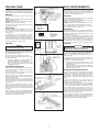
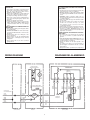
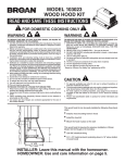
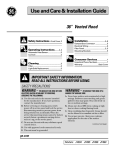
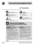
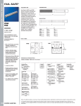
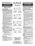
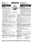
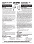
SERIE 15000
CAMPANA DE COCINA
DE 30 PULG.
15000 SERIES
30" RANGE HOOD
READ AND SAVE
THESE INSTRUCTIONS
LEA Y CONSERVE
ESTAS INSTRUCCIONES
INTENDED FOR
DOMESTIC COOKING ONLY.
PREVISTO PARA COCINAR
DOMÉSTICO SOLAMENTE.
PRECAUCION
WARNING
TO REDUCE THE RISK OF FIRE, ELECTRIC SHOCK,
OR INJURY TO PERSONS, OBSERVE THE FOLLOWING:
1. Use this unit only in the manner intended by the
manufacturer. If you have questions, contact the
manufacturer at the address or telephone number
listed in the warranty.
2. Before servicing or cleaning unit, switch power off
at service panel and lock the service disconnecting
means to prevent power from being switched on accidentally. When the service disconnecting means
cannot be locked, securely fasten a prominent
warning device, such as a tag, to the service panel.
3. Installation work and electrical wiring must be done
by a qualified person(s) in accordance with all applicable codes and standards, including fire-rated
construction codes and standards.
4. Sufficient air is needed for proper combustion and
exhausting of gases through the flue (chimney) of
fuel burning equipment to prevent backdrafting. Follow the heating equipment manufacturer’s guideline
and safety standards such as those published by the
National Fire Protection Association (NFPA), and the
American Society for Heating, Refrigeration and Air
Conditioning Engineers (ASHRAE), and the local
code authorities.
5. When cutting or drilling into wall or ceiling, do not
damage electrical wiring and other hidden utilities.
6. Do not use this range hood with an additional speed
control device.
7. Ducted fans must always be vented to the outdoors.
8. To reduce the risk of fire, use only metal ductwork.
9. Use with approved cord-connection kit only.
10. This unit must be grounded.
TO REDUCE THE RISK OF A RANGE TOP GREASE
FIRE:
1. Never leave surface units unattended at high
settings. Boilovers cause smoking and greasy
spillovers that may ignite. Heat oils slowly on low
or medium settings.
2. Always turn hood ON when cooking at high heat
or when cooking flaming foods.
3. Clean ventilating fans frequently. Grease should
not be allowed to accumulate on fan or filter.
4. Use proper pan size. Always use cookware appropriate for the size of the surface element.
TO REDUCE THE RISK OF INJURY TO PERSONS
IN THE EVENT OF A RANGE TOP GREASE FIRE,
OBSERVE THE FOLLOWING:*
1. SMOTHER FLAMES with a close-fitting lid, cookie
sheet, or metal tray, then turn off the burner. BE
CAREFUL TO PREVENT BURNS. If the flames
do not go out immediately, EVACUATE AND CALL
THE FIRE DEPARTMENT.
2. NEVER PICK UP A FLAMING PAN - You may be
burned.
3. DO NOT USE WATER, including wet dishcloths or
towels - a violent steam explosion will result.
4. Use an extinguisher ONLY if:
A. You know you have a Class ABC extinguisher
and you already know how to operate it.
B. The fire is small and contained in the area
where it started.
C. The fire department is being called.
D. You can fight the fire with your back to an exit.
* Based on “Kitchen Fire Safety Tips” published
by NFPA.
Register your product online at:
www.broan.com/register
INSTALLER: Leave This Manual
With Homeowner. HOMEOWNER:
Use and Care Information on page 4.
INSTALADOR: Deje este manual con el
dueño de la casa. DUEÑO DE LA CASA:
Información acerca del uso y mantenimiento
en la página 4.
PARA REDUCIR EL RIESGO DE INCENDIO, CHOQUE
ELECTRICO, O LESION A PERSONAS, PROCURE LO
SIGUIENTE:
1. Utilice esta unidad sólo en la manera prescrita por el
fabricante. Si tiene usted alguna pregunta, comuníquese
con el fabricante a la dirección o el teléfono indicados en
la garantía.
2. Antes de limpiar o de poner en servicio la unidad, apague
el interruptor en el panel de servicio, y asegure el panel
de servicio para evitar que se encienda accidentalmente.
Cuando el dispositivo para desconectar el servicio eléctrico no puede ser cerrado con algún tipo de traba,
sujete fuertemente al panel de servicio, una etiqueta de
advertencia prominente.
3. Todo trabajo de instalación y cableado eléctrico debe ser
realizado por personal calificado y de acuerdo con todos
los códigos y normas pertinentes, incluyendo los códigos
y normas relacionados con construcción clasificada para
incendio.
4. Aire suficiente es necesario para facilitar la combustión
adecuada y la salida apropiada de gases por la chimenea
de la unidad y para evitar corrientes de aire invertidas.
Siga las instrucciones y medidas de seguridad del
fabricante del equipo y de las sociedades profesionales
de equipos de calentadores y los reglamentos de
seguridad locales.
5. A cortar o perforar la pared o el techo, no dañe el cableado
eléctrico u otros servicios públicos ocultos a la vista.
6. No utilice este ventilador con ningún dispositivo de una
control de velocidad de estado sólido adicional.
7. Los abanicos con ducto deberán siempre tener una salida
hacia el exterior.
8. Para reducir el riesgo de incendio, use sólo ductos de
metal.
9. Uso con el kit aprobado del la conexión de la cuerda
solamente.
10. Esta unidad se debe instalar con tierra efectiva.
PARA REDUCIR EL RIESGO DE INCENDIO DEBIDO A
GRASA ACUMULADA EN LAS HORNILLAS:
1. Nunca deje sin atender las unidades de superficie cuando
tengan ajustes altos. Los reboses pueden provocar humo
y derrames grasosos que se pueden incendiar. Caliente
lentamente el aceite en un ajuste bajo o medio.
2. Siempre ENCIENDA la campana cuando cocine con alta
temperatura o cuando cocine alimentos que se puedan
incendiar.
3. Limpie con frecuencia los ventiladores. No debe permitir
que la grasa se acumule en el ventilador ni en el filtro.
4. Utilice un sartén de tamaño adecuado. Siempre utilice el
utensilio adecuado al tamaño del elemento de superficie.
PARA REDUCIR EL RIESGO DE LESION A PERSONAS
RESULTADO DE UN INCENDIO DEBIDO A GRASA ACUMULADA EN LAS HORNILLAS, PROCURE LO SIGUIENTE:*
1. AHOGUE LAS LLAMAS con una tapa ajustada o
charola de metal, después apague la hornilla. TENGA
CUIDADO A FIN DE EVITAR QUEMADURAS. Si las
llamas no se apagan de inmediato, EVACUE Y AVISE
A LOS BOMBEROS.
2. NO LEVANTE NUNCA UNA SARTEN QUE ESTE EN
LLAMAS - Usted se podrá quemar.
3. NO UTILICE AGUA, incluyendo toallas de cocina mojadas
- puede resultar una explosión de vapor violenta.
4. Utilice un extinguidor SOLAMENTE si:
A. Usted sabe que tiene un extinguidor de clase ABC y lo sabe utilizar.
B.El incendio es pequeño y contenido dentro del área donde se inició.
C. Los bomberos han sido avisados.
D. Usted puede combatir el incendio con una salida a
su espalda.
* Basado en las recomendaciones para “Seguridad en la
Cocina” publicadas por la NFPA de los EEUU.
Registre su producto en línea en:
www.broan.com/register
CAUTION
1.
2.
3.
4.
5.
6.
For indoor use only.
For general ventilating use only. Do not use to
exhaust hazardous or explosive materials and
vapors.
To avoid motor bearing damage and noisy and/
or unbalanced impellers, keep drywall spray,
construction dust, etc. off power unit.
When using a thermostat with this product, fan
may start automatically. To reduce the risk of injury,
switch power off at service panel and lock service
panel to prevent power from being switched on
accidentally.
Your hood motor has a thermal overload which
will automatically shut off the motor if it becomes
overheated. The motor will restart when it cools
down. If the motor continues to shut off and restart,
have the hood serviced.
Please read specification label on product for
further information and requirements.
PLAN THE
INSTALLATION
Your new hood will fit a standard 30" wide flush bottom
or recessed bottom, framed or frameless kitchen cabinet
which has a minimum depth of 11" from face to inside
of back wall.
The unit is ducted vertically. Horizontal ducting can be
accomplished as shown.
For safe operation, the mounted hood must be a minimum of 18" above the cooking surface.
For easiest installation, range hood should be installed
in cabinet before mounting cabinet to wall.
NOTE
REMOVE GLASS DRAWER FROM UNIT BEFORE
INSTALLING HOOD IN CABINET TO PROTECT
DRAWER FROM DAMAGE. SEE STEP 13 ON
PAGE 3.
PRECAUCION
FIG. 1
1.
2.
11"
27,94 CM
MIN.
(INSIDE)
(ADENTRO)
11"
27,94 CM
MIN.
(INSIDE)
(ADENTRO)
3.
4.
18" MIN.
45,72 CM MIN.
18" MIN.
45,72 CM MIN.
FLUSH BOTTOM CABINET
GABINETE CON FONDO A RAS
FIG. 2
2-5/8"
6,67 CM
"
RECESSED BOTTOM CABINET
GABINETE CON FONDO AHUECADO
CABINET CENTER LINE
LINEA CENTRAL DEL GABINETE
24-1/2"
62,23 CM
"
9-1/2"
24,13 CM
CUT-OUT
HUECO
14"
35,56 CM
25-5/8"
65,09 CM
CABINET BOTTOM VIEW
VISTA DESDE LA PARTE
INFERIOR DEL GABINETE
FIG. 3
6.
CABINET FRONT
FRENTE DEL
GABINETE
1-5/8"
4,13 CM
13-1/2"
34,29 CM
7"
17,78 CM
(4) 3/8" DIA.
0,95 CM DIA.
CLEARANCE
HOLES
AGUJEROS DEL
CLARO
2.
3.
4.
5.
Mark and cut-out cabinet bottom. (FIG. 2)
Prepare the cabinet bottom as shown in Figure 2.
Be sure to locate the cut-out and four holes from
the front of the cabinet to assure a flush mount.
Attach damper/duct connector. (FIG. 3)
Use two (2) screws (provided) to attach connector
to housing. Damper flap should open in direction
indicated by arrow.
Remove electrical knockout.
Choose either the top or side of housing for
electrical cable entrance. Remove the appropriate
knockout.
Set housing into opening. (FIG. 4)
Carefully lower housing into cabinet opening with
slide control to the front.
Remove access cover. (FIG. 5)
u nuevo extractor cabrá en la parte inferior de un gabinete
S
estándar de 76,2 cm con la parte inferior a ras o ahuecada,
con o sin marco, que tenga una profundidad mínima de 27,94
cm desde la parte frontal hacia a la pared.
El ducto de la unidad sube verticalmente. A un ducto horizontal se lo puede instalar como se muestra.
Para operación segura, el extractor ya montado tiene que estar a un mínimo de 45,72 cm sobre la superficie de la cocina. Para una instalación más fácil, al extractor debe de instalárselo en el gabinete antes de montar el gabinete en la
pared. NOTESE
QUITE EL CAJÓN DE VIDRIO DE LA UNIDAD ANTES
DE INSTALAR EL EXTRACTOR EN EL GABINETE
PARA EVITAR DAÑAR EL CAJÓN. VÉASE PASO 13
EN PÁGINA 3.
A este extractor se lo puede instalar fácilmente siguiendo
estos pasos básicos:
• Marque y corte el hueco en la parte inferior del gabinete.
• Sujete el extractor al gabinete.
• Monte el gabinete sobre la pared.
• Conecte los ductos y el cableado. (FIG. 1)
#8-18 x 3/8"
1.
PLANIFIQUE LA
INSTALACION
ELECTRICAL KNOCKOUTS
PLACAS DE QUITAR GOLPEANDO
This hood can easily be installed by following these
basic steps:
• Mark and cut out cabinet bottom.
• Secure hood to cabinet.
• Mount cabinet on wall.
• Connect ductwork and power cable. (FIG. 1)
INSTALL THE HOOD
5.
Para uso de interior solamente.
Solamente para uso general de ventilación. No utilice
para descargar materiales o vapores riesgosos o
explosivos.
Para evitar daños al motor y evitar que las navajas del
abanico emitan mucho ruido o estén fuera de balance,
mantenga el motor libre de pelusa, polvo, etc.
Si usa un termóstato con este producto, el abanico
puede arrancar automáticamente. Para reducir el riesgo
de lesiones, apague la fuerza eléctrica en el panel de
servicio y cierre con llave el panel de servicio para evitar
que alguien prenda la fuerza eléctrica accidentalmente.
El motor de su extractor tiene dispositivo de sobrecarga
térmica, al cual automáticamente apagará el motor si se
sobrecalienta. El motor funcionará de nuevo cuando se
enfríe. Si el motor continua apagándose y arrancando,
hágalo componer.
Por favor lea la etiqueta con las especificaciones del
equipo para otros requisitos y mayor información.
FIG. 4
INSTALE EL EXTRACTOR
1.
SLIDE CONTROL
CONTROL DE DESLIZAR
2.
3.
FIG. 5
4.
ACCESS COVER
TAPA DE ACCESO
2
5.
Marque y corte el hueco en la parte inferior del gabinete. (FIG. 2)
Prepare la parte inferior del gabinete como se muestra
en Fig. 2. Asegúrese que localice el hueco y los cuatro
agujeros desde la parte frontal del gabinete para asegurarse que se monte a ras.
Sujete el conector para el regulador/ducto. (FIG. 3)
Use dos (2) tornillos (suministrados) para sujetar el
conector al bastidor. La placa del regulador debe de
abrirse en la dirección de la flecha.
Quite la placa de quitar golpeando.
Escoja, ya sea la parte superior, o parte lateral del
bastidor para la entrada de cable eléctrico. Quite la
placa de quitar golpeando apropiada.
Ponga el bastidor dentro del hueco. (FIG. 4)
Con cuidado meta el bastidor dentro del hueco del
gabinete con el control de deslizar hacia en frente.
Quite la tapa de acceso. (FIG. 5)
6. Open filter panel. (FIG. 6 & 7)
Pull drawer slides out. Rotate panel clips and swing
panel open.
7. Install mounting brackets.
Insert bent end of installation rod into access hole
in housing. (FIG. 8)
Choose the mounting bracket with the center hole.
Hang the bracket from the rod, through this center
hole, as shown. Pull bracket up between cabinet
and housing. (FIG. 9)
Hold mounting bracket in place with rod. Two sets
of screws are provided. Use short screws for flush
bottom cabinets or long screws for recessed bottom
cabinets. Insert two (2) screws through housing
and into mounting bracket. Do not tighten screws
completely. (FIG. 10)
Insert two (2) screws, short or long as appropriate,
through control box and into other mounting bracket.
Do not tighten screws completely. (FIG. 11)
8. Secure hood to cabinet. (FIG. 12)
Align hood with sides and front edge of cabinet.
Tighten screws in each mounting bracket. Place
plastic caps (provided) over the ends of these
screws from inside of cabinet.
Install two (2) additional screws into cabinet bottom,
through holes along the front edge of hood. (See
FIG. 11)
9. Replace access cover.
Secure access cover with two (2) screws removed
in Step 5.
10. Mount cabinet on wall.
Make sure cabinet is securely attached to the wall
and/or adjoining cabinets. Mounted cabinet must
be able to support the added weight of the hood.
11. Attach ductwork and front trim. (FIG. 13)
Complete the ductwork from the hood, to the outside, using a roof cap or elbow and wall cap. Tape
all joints. Shelves may be installed if trimmed to
clear ductwork.
The front trim piece covers the gap between the
housing and the front edge of cabinet cut-out.
Mount front trim to housing with two (2) screws
(provided).
12. Connect electrical wiring. (FIG. 14)
Remove the wire box cover. Attach power cable
to hood using proper connector. Connect black
to black, white to white and green or bare wire to
ground screw. Replace wire box cover.
FIG. 6
PANEL CLIP
GRAMPA DEL PANEL
FIG. 7
DRAWER SLIDES
DESLIZADORES DEL CAJON
FIG. 8
ACCESS HOLE
HUECO DE ACCESO
INSTALLATION ROD
VARILLA DE INSTALACION
FIG. 9
CAUTION
DO NOT CONNECT POWER AT SERVICE ENTRANCE AT THIS TIME.
13. Install glass drawer assembly. (FIG. 15)
Slide the glass into the drawer slides, above each
drawer clamp (see FIG. 16). Align drawer trim and
tighten thumb screws to secure drawer.
To remove glass drawer:
Simply loosen thumb screws and pull glass from
drawer slides.
14. Fine adjustments to drawer trim position.
(FIG. 16)
The drawer slides each have a screw for adjusting
the height of the drawer trim, if necessary. The
vertical adjustment screw allows the top and bottom
edges of the drawer trim to be matched with the
control trim.
15. Connect power at service entrance.
16. Check operation.
CENTER HOLE
HUECO CENTRAL
MOUNTING BRACKET
SOPORTE MONTANTE
FIG. 10
#8-18 x 2"
OR
#8-18 x 1"
INSERT SCREWS
HERE
INSERTE TORNILLOS AQUI
3
6. Abra el panel del filtro. (FIG. 6 & 7)
Tíre los deslizadores del cajón hacia afuera. De la vuelta
a las grampas del panel y abra el panel.
7. Instale los soportes para montar.
Inserte la parte doblada de la varilla de instalación
dentro del hueco de acceso en el bastidor. (FIG. 8)
Escoja el soporte montante con el hueco central. Cuelgue el soporte de la varilla a través de este hueco
central como se muestra. Tire el soporte hacia arriba
entre el gabinete y el bastidor. (FIG. 9)
Sostenga el soporte montante en su sitio con la varilla. Se han suministrado dos juegos de tornillos. Use los
tornillos cortos para gabinetes con el parte inferior a
ras, o tornillos largos para gabinetes con la parte inferior
ahuecada. Inserte dos (2) tornillos a través del bastidor
y dentro del soporte montante. No ajuste los tornillos
completamente. (FIG. 10)
Inserte dos (2) tornillos, cortos o largos como sea
apropiado, a través de la caja de control y dentro
del otro soporte montante. No ajuste los tornillos
completamente. (FIG. 11)
8. Sujete el extractor al gabinete. (FIG. 12)
Alinee el extractor con los lados y el frente del gabinete.
Ajuste los tornillos dentro de cada soporte montante.
Ponga las tapas de plástico (suministradas) sobre los
extremos de estos tornillos desde la parte interior del
gabinete. Instale dos tornillos adicionales dentro de la parte inferior
del gabinete, a través de los huecos, a lo largo del filo
del frente del extractor. (Véase FIG. 11)
9. Reemplace la tapa de acceso.
Asegure la tapa de acceso con los dos (2) tornillos que
se quitaron en el paso 5.
10. Monte el gabinete sobre la pared.
Asegúrese que el gabinete esté bien sujetado a la pared
y/o los gabinetes contiguos. El gabinete ya instalado
debe de poder aguantar el peso adicional del extractor.
11. Sujete el ducto y los adornos del frente. (FIG. 13)
Complete los ductos desde el extractor hacia la parte
exterior usando un casquete para el techo, o un codo
y un casquete para la pared. Ponga cinta aislante en
todas las uniones. Se pueden instalar estantes si se los
recorta para que pasen alrededor del ducto.
El adorno del frente cubre el espacio entre el bastidor
y el filo frontal del hueco en el gabinete. Monte el
adorno del frente al bastidor con dos (2) tornillos
(suministrados). 12. Conecte el cableado eléctrico. (FIG. 14)
Quite la tapa del cableado. Sujete el cable de fuerza
eléctrica al extractor usando el conector apropiado.
Conecte alambre negro a negro, blanco a blanco
y verde, o alambre desnudo, al tornillo de tierra.
Reemplace la tapa de la caja del cableado.
PRECAUCION
NO CONECTE LA POTENCIA ELECTRICA EN LA
ENTRADA DE SERVICIO ESTE MOMENTO.
13. Instale el ensamblaje de la caja de vidrio. (FIG. 15)
Deslice el vidrio sobre los deslizadores del cajón,
encima de cada abrazadera del cajón (véase FIG. 16). Alinee el adorno del cajón y ajuste los tornillos de dedo
para asegurar el cajón.
Para quitar el cajón de vidrio:
Simplemente afloje los tornillos de dedo y tire el vidrio
fuera de los deslizadores del cajón.
14. Ajustes finos para la posición del adorno de cajón.
(FIG. 16)
Cada uno de los deslizadores del cajón tiene un tornillo
para ajustar el alto del adorno del cajón, si ésto fuera
necesario. El tornillo de ajuste vertical permite que los
filos de arriba y abajo del adorno del cajón, se alineen
con el adorno de control.
15. Conecte la fuerza eléctrica en la entrada de servicio.
16. Chequee la operación.
USE AND CARE
Always turn your hood on before you begin cooking to
establish an air flow in the kitchen. Let the hood run for
a few minutes to clean the air after you turn the range
off. This will keep the whole kitchen cleaner and brighter.
Controls
The hood is “OFF” when the drawer is pushed completely in.
LIGHT - The light will turn “ON” when the drawer is pulled
out approximately 1/2 inch.
BLOWER - The blower will turn “ON” when the drawer
is pulled out approximately 1-1/2 inches.
The blower speed is set using the slide control, located
to the right of the drawer.
Heat Sentry™
Your hood is equipped with a Heat Sentry™ thermostat.
This thermostat is a device that will turn on or speed
up the blower if it senses excessive heat above the
cooking surface.
If your blower is not on, or if it is running at low speed,
the Heat Sentry™ will sense excessive cooking heat,
override the normal blower control and turn the blower on
to high speed. The blower will run until the temperature
drops to normal operating level. The blower will then
automatically return to its original setting.
FIG. 11
INSERT
SCREWS HERE
INSERTE TORNILLOS AQUI
CONTROL BOX
CAJA DE CONTROL
FRONT MOUNTING
HOLE SEE STEP 8.
HUECO FRONTAL
PARA MONTAR.
VEASE PASO 8.
MOUNTING BRACKET
SOPORTE MONTANTE
#8-18 x 2"
OR
Controles
El extractor está apagado (“OFF”) cuando se ha empujado
al cajón completamente hacia adentro. LUZ - La luz se prenderá (“ON”) cuando se ha tirado el cajón
hacia afuera aproximadamente 1,27 cm.
ABANICO - El abanico se prenderá (“ON”) cuando se ha
tirado el cajón hacia afuera aproximadamente 3,81 cm.
A la velocidad del abanico se la fija usando el control deslizante, localizado a la derecha del cajón.
Su extractor está equipado con un termóstato Heat Sentry.™
Este termóstato es un dispositivo que prenderá o acelerará la
velocidad del abanico cuando perciba calor excesivo encima
de la superficie de fogón.
Si su abanico no está prendido, o está funcionando a baja
velocidad, el Heat Sentry™ percibirá el calor excesivo del
fogón, quitará el control normal del abanico, y acelerará al
abanico a alta velocidad. El abanico funcionará hasta que
la temperatura baje al nivel normal de operación. El abanico
entonces automáticamente regresará a su fijación original.
FIG. 12
PLASTIC CAP
TAPA DE PLASTICO
#8-18 x 1/2"
FIG. 13
Limpieza
WARNING
ALWAYS DISCONNECT ELECTRIC POWER SUPPLY BEFORE SERVICING HOOD.
FRONT TRIM
ADORNO DEL
FRENTE
3-1/4" X 10"
DUCTWORK
DUCTO
FIG. 14
GROUND SCREW
TORNILLO DE TIERRA
WIRE BOX COVER
TAPA DE LA CAJA DE
CABLEADO
Light Bulb Replacement
Your hood uses a 24" long F20T12 fluorescent tube and
an FS-2 starter, which are available at most hardware
stores or home centers.
To check or replace tube: 1) Pull drawer out. 2) Rotate
filter panel clips and lower filter panel.
If the tube flickers or does not light, check the prongs
on the ends of the tube to make sure they are properly
seated in the tube holders.
If the tube continues to flicker or does not light, replace
the tube. Slide the tube into the holders and rotate the
tube so that the prongs in the holders grip the tube and
hold it in place.
If the ends of the tube light but the center does not, the
starter may require replacement. The starter is located
behind the filter panel on the right hand side. Install
the new starter by pushing the starter in and turning
it clockwise.
If the tube still does not light, order a 99270651 Ballast
Transformer available from your Broan distributor or from
the Broan Service Department. Write Broan-NuTone
LLC, PO Box 140, Hartford, WI 53027.
Siempre prenda el extractor antes de que comience a guisar
para establecer un flujo de aire en la cocina. Deje que el
extractor funcione por unos pocos minutos para limpiar el
aire después de que haya apagado el fogón. Esto mantendrá
toda la cocina más limpia y más clara.
Heat Sentry™
#8-18 x 1"
Cleaning
Use a mild detergent suitable for painted surfaces. DO
NOT USE ABRASIVE CLOTH, STEEL WOOL PADS,
OR SCOURING POWDERS. Vacuum blower to clean.
Do not immerse blower in water.
Wash the foam filter in a mild detergent solution.
The glass drawer assembly and light lens are easily
removable for cleaning:
See Step 13 on page 3 for removal of glass drawer
assembly. DO NOT clean in a dishwasher.
Remove the light lens by opening the filter panel
(Step 6, page 3) and rotating the 2 metal clips
holding the lens in place.
USO Y MANTENIMIENTO
PRECAUCION
SIEMPRE DESCONECTE LA ENERGIA ELECTRICA
ANTES DE DAR SERVICIO AL EXTRACTOR.
Use un detergente suave apropiado para superficies
pintadas NO USE TRAPOS ABRASIVOS, ALMOHADILLAS
DE LANA DE ACERO O POLVOS DE FREGAR. Aspire el
abanico con una aspiradora para limpiarlo. No meta el
abanico en el agua.
Lave el filtro de espuma en una solución de detergente suave.
Al ensamblaje del cajón de vidrio y al lente de la luz, se los
puede quitar con facilidad para limpiarlos:
Véase paso 13 en página 3 para saber como sacar el
ensamblaje del cajón de vidrio. NO lo limpie en una
lavadora de platos.
Quite el lente de la luz abriendo el panel del filtro (Paso
6, página 3) y dando vuelta a dos grapas de metal que
sostienen al lente en su sitio.
Reemplazo del Bombillo de Luz
FIG. 15
CONTROL TRIM
ADORNO DE CONTROL
DRAWER TRIM
ADORNO DEL CAJON
THUMB SCREWS
TORNILLOS DE
DEDO
DRAWER SLIDE
DESLIZADOR DEL CAJON
FIG. 16
DRAWER CLAMP
ABRAZADERA DE CAJON
VERTICAL ADJUSTMENT SCREW
TORNILLO PARA
AJUSTE VERTICAL
THUMB SCREWS
TORNILLOS DE DEDO
4
Su extractor usa un tubo fluorescente de 60,96 cm de largo
F20T12 y un arrancador FS-2, disponible en la mayoría de
las ferretarías o centros que venden árticulos para la casa.
Para chequear o reemplazar el tubo: 1) Saque el cajón. 2)
Dé la vuelta a las grapas del panel del filtro y baje el panel
del filtro.
Si el tubo de luz parpadea o no se prende, chequee las
puntas del fin de tubo para asegurarse que estén bien
asentadas en los sostenes del tubo.
Si el tubo continúa parpadeando o no se prende, reemplácelo. Resbale el tubo y dele vuelta de manera que las puntas
en los sostenes agarren al tubo y lo sostengan en su sitio.
Si los extremos del tubo se prenden, pero el centro no se
prende, es posible de que haya reemplazar el arrancador. El arrancador está localizado detrás del panel del filtro a
mano derecha. Instale un nuevo arrancador empujándolo y
dándole la vuelta en dirección horaria. Si el tubo todavía no se prende, ordene el transformador de
lastre #99270651 disponible donde su distribuidor Broan o
del departamento de servicio de Broan. Escriba a BroanNuTone LLC, PO Box 140, Hartford, WI 53027.
HOW TO AVOID A COMMON RANGE-TOP
GREASE FIRE
• Your range hood provides a protective barrier
between the cooking surface and the cabinets.
• Keep fan, filters and grease laden surfaces
CLEAN according to instructions.
• Always turn hood ON when cooking at high heat
to keep the cooking area and the hood cooler.
• Use high heat settings only when necessary.
• Never leave cooking surface unattended. Boilover causes smoking and greasy spillovers that
may ignite.
• Always use adequate-sized utensils.
• If preparing flaming foods, such as Cherries
Jubilee, always turn hood ON to HIGH to prevent a high heat situation which can cause damage
or fire.
HOW TO EXTINGUISH A COMMON RANGE-TOP
GREASE FIRE
• Never pick up a flaming pan. If dropped, flames
can spread quickly.
• DO NOT USE WATER! A violent steam explosion may result. Wet dishcloths or towels are also
dangerous.
• Smother flames with a close fitting lid, cookie
sheet or metal tray.
• Flaming grease can also be extinguished with
baking soda or a multi-purpose dry chemical
extinguisher.
• Turn off surface units - if you can do so without
getting burned.
COMO EVITAR QUE OCURRA UN INCENDIO DEBIDO
A LA GRASA QUE SE ACUMULA EN UN EXTRACTOR COMUN
• Su extractor proporciona una barrera protectora entre
la superficie para cocinar y los gabinetes.
• Mantenga el abanico, los filtros y las superficies donde
se acumula la grasa LIMPIAS conforme a las instrucciones.
• ENCIENDA siempre el extractor cuando esté cocinando a fuego alto para mantener el area para cocinar
y el extractor limpios.
• Utilice las hornillas de fuego alto solamente cuando
sea necesario.
• No deje las hornillas de la estufa sin atención
cuando esté cocinando. El vapor o el aceite que salpique puede ocasionar un incendio o acumulación de humo.
• Siempre utilice los utensilios del tamaño adecuado.
• Si está preparando alimentos flameados, como las
Cerezas a la Jubilee, ENCIENDA siempre el ex-
tractor en ALTO para evitar que el calor pueda causar
algún daño o un incendio.
COMO EXTINGUIR UN INCENDIO EN UN EXTRACTOR COMUN
• No levante nunca una sartén que esté en llamas.
Si se le cae, las llamas se pueden extender rapidamente.
• ¡NO UTILICE AGUA PARA APAGARLO! Puede ocasionar una explosión de vapor. Las toallas de cocina
mojadas también son peligrosas.
• Ahogue las llamas con una tapa ajustada o una
charola.
• Las llamas provocadas por la grasa también se
pueden apagar con bicarbonato de sodio o un extinguidor químico.
• Apague las hornillas - si puede hacerlo sin quemarse.
WIRING DIAGRAM
DIAGRAMA DEL ALAMBRADO
FLUORESCENT LAMP
LAMPARA FLUORESCENTE
CONTROL BOARD
TABLERO DE CONTROL
RED
ROJO
(SYMBOLIC)
(SIMBOLICO)
WHITE
BLANCA
GREEN
VERDE
GREEN
VERDE
BLACK
NEGRO
BLACK
NEGRO
M
LIGHT
LUZ
THERMOSTAT
TERMOSTATO
BLACK
NEGRO
RED
ROJO
WIRING BOX
CAJA DE CABLEADO
YELLOW
AMARILLO
BLACK
NEGRO
BLACK
NEGRO
BLUE
AZUL
BLACK
NEGRO
BLUE
AZUL
ORANGE
ANARANJADO
FAN
VENTILADOR
120 VAC LINE IN
120 VCA LINEA ENTRADA
WHITE
BLANCA
ORANGE
ANARANJADO
BALLAST TRANSFORMER
TRANSFORMADOR DE LASTRE
BLACK
NEGRO
BLACK
NEGRO
WHITE
BLANCA
RED
ROJO
S
CONTROL BOX
CAJA DE CONTROL
HOUSING
BASTIDOR
5
SERVICE PARTS
PIEZAS DE SERVICIO
15000 SERIES
30" RANGE HOOD
SERIE 15000
CAMPANA DE COCINA DE 30 PULG.
KEY NO.
NO.
CODIGO
BLACK
PART NO.
NO.
PIEZA
NEGRA
98010015
99150526
99090677
99360133
99170245
97006078
98005221
99100379
97015950
97015949
93260454
97008578
97008618
99160344
99150538
99150537
97009433
99230345
99160319
98005860
99270550
99270651
99270553
97015775
99400042
98006937
98006938
99100463
97008971
97009436
99250932
97008929
99110683
99420602
98007155
99020139
98005212
99100491
99080359
99260476
99420464
97007314
99020138
99140156
99010175
97011138
99050018
99150492
99100408
99150471
97008628
97005985
1
2
3
4
5
6
7
8
9
**
10
12
13
14
15
**
16
17
18
19
20
21
22
23
24
25
26
27
28
**
29
30
31
32
33
34
35
36
37
38
39
40
41
42
43
44
46
48
49
50
**
**
WHITE
STAINLESS
PART
PART NO.
NO.
NO.
PIEZA
PIEZA
BLANCA INOXIDABLE
DESCRIPTION
98010015
99150478
99090697
99360140
99170245
97006078
98005221
99100379
97015950
97015949
93260454
97008578
97008618
99160344
99150538
99150537
97009433
99230342
99160319
98005860
99270550
99270651
99270553
97015775
99400042
98007164
98006938
99100463
97008979
97009435
99250932
97009054
99110699
99420603
98007155
99020139
98005212
99100491
99080359
99260476
99420464
97007314
99020138
99140156
99010175
97011139
99050018
99150492
99100464
99150471
97008628
97005985
98010015
99150478
99091030
99360249
99170245
97006078
98005221
99100379
97015950
97015949
93260454
97008578
97008618
99160344
99150538
99150537
97009433
99230342
99160319
98005860
99270550
99270651
99270553
97015775
99400042
98010173
98006938
99100463
97016556
97016555
99250932
97016559
--------
99420602
98007155
99020139
98005212
99100491
99080359
99260476
99420464
97007314
99020138
99140156
99010175
97016557
99050018
99150492
99100408
99150471
97008628
97005985
Front Trim
Screw #8-18 x 3/8 (14 Required)*
Control Trim
Control Knob
Screw #8-18 x 3/8 (8 Required)*
Damper Assembly (Includes Key Nos. 7 & 8)
Damper Flap
Damper Bushing
RH Mounting Bracket (Includes Key No. 10)
LH Mounting Bracket (Includes Key No. 10)
#8 Sheet Metal Nut “U” Type (11 Required)
Variable Speed Slide-Control Board
Control Harness
Screw #8-32 x 3/16 (5 Required)*
Screw #8-18 x 2 (4 Required)*
Screw #8-18 x 1 (4 Required)*
Blower Switch/Light Switch/Heat Sentry™
Assembly
Rivet (12 Required)
Screw #6-32 x 3/8 (4 Required)*
Lampholder Bracket (2 Required)
Lampholder (2 Required)
Ballast Transformer
Starter FS-2*
Light Harness
Strain Relief Bushing SR-4N-4 (2 Required)
Access Cover
Wire Box Cover
Drawer Stop (2 Required)
LH Drawer Bracket Assembly (Includes Key Nos. 32 & 33)
RH Drawer Bracket Assembly (Includes Key Nos. 32 & 33)
Washer (2 Required)*
Drawer Assembly (Includes Key Nos. 14 & 31)
Drawer End Cap
Thumb Screw (4 Required)
Drawer Clamp (2 Required)
Blower Wheel, Counterclockwise
Motor Retaining Ring (2 Required)
Rubber Motor Mount (4 Required)
Motor
Blower Mounting Rod Nut (2 Required)
Blower Mounting Rod (2 Required)
Blower Scroll Housing
Blower Wheel, Clockwise
Filter Spring (2 Required)
Filter Foam
Filter Panel
Light Lens
Screw #8-18 x 1/2 (2 Required)*
Plastic Cap (4 Required)
Screw #10-32 x 1/2 Green (2 Required)
Green Wire Assembly
Complete Blower Assembly
(Includes Key Nos. 5, 34, 35, 36, 37, 40, 41)
Fluorescent Light Tube F20T12* (Not Included)
* Standard Hardware. May be purchased locally.
** Not Illustrated
Order replacement parts by “PART NO.” – NOT
by “KEY NO.”
Replacement parts can now be
ordered on our website.
Please visit us at www.Broan.com
6
DESCRIPCION
Adorno frontal
Tornillo #8-18 x 3/8 (se requieren 14)*
Adorno de control
Perilla de control
Tornillo #8-18 x 3/8 (se requieren 8)*
Ensamblaje de regulador (incluye números clave 7 & 8
Placa de regulador
Buje de regulador
Soporte montante mano derecha (incluye número clave 10)
Soporte montante mano izquierda (incluye número clave 10)
Tuerca de lámina de metal #8 tipo “U” (se requieren 11)
Tablero de control deslizante para velocidad variable
Alambrado de control
Tornillo #8-32 x 3/16 (se requieren 5)*
Tornillo #8-18 x 2 (se requieren 4)*
Tornillo #8-18 x 1 (se requieren 4)*
Ensamblaje de interruptor del abanico/interruptor/luz/Heat Sentry™
Remaches (se requieren 12)
Tornillo #6-32 x 3/8 (se requieren 4)*
Soporte de bombillo o tubo de luz (se requieren 2)
Sostén de bombillo o tubo (se requieren 2)
Transformador de lastre
Arrancador FS-2*
Harnés o alambrado de la luz
Buje para aguantar tensión SR-4N-4 (se requieren 2)
Tapa de acceso
Tapa de la caja del cableado
Sostén de cajón (se requieren 2)
Ensamblaje de soporte de cajón mano izquierda
(incluye números clave 32 & 33)
Ensamblaje de soporte de cajón mano derecha (incluye números clave 32 & 33)
Arandelas (se requieren 2)*
Ensamblaje del cajón (incluye números clave 14 & 31)
Tapa del extremo de cajón
Tornillo de dedo (se requieren 4)
Abrazadera de cajón (se requieren 2)
Rueda del motor, dirección antihoraria
Anillo retentor motor (se requieren 2)
Montante del caucho de motor (se requieren 4)
Motor
Tuerca de la varilla montante del abanico (se requieren 2)
Varilla montante del abanico (se requieren 2)
Bastidor del abanico
Rueda del abanico, dirección horaria
Resorte del filtro (se requieren 2)
Filtro de espuma
Panel de filtro
Lente de la luz
Tornillo #8-18 x 1/2 (se requieren 2)*
Tapa de plástico (se requieren 4)
Tornillo #10-32 x 1/2 verde (se requieren 2)
Ensamblaje de alambre verde
Ensamblaje completo del abanico (incluye números clave 5, 34, 35, 36, 37, 40, 41)**
Tubo fluorescente F20T12* (no se incluye)
* Herrajes estándar. Pueden comprarse localmente.
** No está ilustrado.
Encargue piezas de servicio por “NO. PIEZA” – NO
por “NO. CODIGO”.
Las piezas de recambio se pueden
ahora pedir en nuestro Web site.
Visítenos por favor en
www.Broan.com
15000 SERIES
30" RANGE HOOD
SERIE 15000
CAMPANA DE COCINA
DE 30 PULG.
7
BROAN-NUTONE ONE YEAR LIMITED WARRANTY
GARANTIA BROAN-NUTONE LIMITADA POR UN AÑO
Broan-NuTone warrants to the original consumer purchaser of its
products that such products will be free from defects in materials
or workmanship for a period of one year from the date of original
purchase. THERE ARE NO OTHER WARRANTIES, EXPRESS
OR IMPLIED, INCLUDING, BUT NOT LIMITED TO, IMPLIED
WARRANTIES OF MERCHANTABILITY OR FITNESS FOR A
PARTICULAR PURPOSE.
Broan-NuTone garantiza al consumidor comprador original de sus
productos que dichos productos carecerán de defectos en materiales
o en mano de obra por un período de un año a partir de la fecha
original de compra. NO EXISTEN OTRAS GARANTIAS, EXPLICITAS
O IMPLICITAS, INCLUYENDO, PERO NO LIMITADAS A, GARANTIAS IMPLICITAS DE COMERCIALIZACION O APTITUD PARA UN
PROPOSITO PARTICULAR.
During this one-year period, Broan-NuTone will, at its option, repair
or replace, without charge, any product or part which is found to be
defective under normal use and service.
Durante el período de un año, y a su propio criterio, Broan-NuTone
reparará o reemplazará, sin costo alguno cualquier producto o pieza
que se encuentre defectuosa bajo condiciones normales de servicio
y uso.
THIS WARRANTY DOES NOT EXTEND TO FLUORESCENT
LAMP STARTERS, TUBES, HALOGEN AND INCANDESCENT
BULBS, FUSES, FILTERS, DUCTS, ROOF CAPS, WALL CAPS
AND OTHER ACCESSORIES FOR DUCTING. This warranty
does not cover (a) normal maintenance and service or (b) any
products or parts which have been subject to misuse, negligence,
accident, improper maintenance or repair (other than by BroanNuTone), faulty installation or installation contrary to recommended
installation instructions.
The duration of any implied warranty is limited to the one-year
period as specified for the express warranty. Some states do not
allow limitation on how long an implied warranty lasts, so the above
limitation may not apply to you.
BROAN-NUTONE’S OBLIGATION TO REPAIR OR REPLACE, AT
BROAN-NUTONE’S OPTION, SHALL BE THE PURCHASER’S
SOLE AND EXCLUSIVE REMEDY UNDER THIS WARRANTY.
BROAN-NUTONE SHALL NOT BE LIABLE FOR INCIDENTAL,
CONSEQUENTIAL OR SPECIAL DAMAGES ARISING OUT OF
OR IN CONNECTION WITH PRODUCT USE OR PERFORMANCE.
Some states do not allow the exclusion or limitation of incidental or
consequential damages, so the above limitation or exclusion may
not apply to you.
This warranty gives you specific legal rights, and you may also
have other rights, which vary from state to state. This warranty
supersedes all prior warranties.
To qualify for warranty service, you must (a) notify Broan-NuTone at
the address or telephone number below, (b) give the model number
and part identification and (c) describe the nature of any defect in
the product or part. At the time of requesting warranty service, you
must present evidence of the original purchase date.
Broan-NuTone LLC, 926 W. State Street, Hartford, Wisconsin 53027
www.broan.com 800-558-1711
LA PRESENTE GARANTÍA NO CUBRE LOS TUBOS FLUORESCENTES NI SUS ARRANCADORES, BOMBILLAS DE HALÓGENO
E INCANDESCENTES, FUSIBLES, FILTROS, CONDUCTOS, TAPONES DE TECHO O PAREDES Y DEMÁS ACCESORIOS PARA
CONDUCTOS. Esta garantía no cubre (a) mantenimiento y servicio
normales o (b) cualquier producto o piezas que hayan sido utilizadas
de forma errónea, negligente, que hayan causado un accidente, o
que hayan sido reparadas o mantenidas inapropiadamente (por otras
compañías que no sean Broan-NuTone), instalación defectuosa, o
instalación contraria a las instrucciones de instalación recomendadas.
La duración de cualquier garantía implícita se limita a un período de
un año como se especifica en la garantía expresa. Algunos estados
no permiten limitaciones en cuanto al tiempo de expiración de una
garantía implícita, por lo que la limitación antes mencionada puede
no aplicarse a usted.
LA OBLIGACION DE BROAN-NUTONE DE REPARAR O REEMPLAZAR, SIGUIENDO EL CRITERIO DE BROAN-NUTONE,
DEBERA SER EL UNICO Y EXCLUSIVO RECURSO LEGAL DEL
COMPRADOR BAJO ESTA GARANTIA. BROAN-NUTONE NO SERA
RESPONSABLE POR DAÑOS INCIDENTALES, CONSIGUIENTES,
O POR DAÑOS ESPECIALES QUE SURJAN A RAIZ DEL USO O
DESEMPEÑO DEL PRODUCTO. Algunos estados no permiten la
exclusión o limitación de daños incidentales o consiguientes, por
lo que la limitación antes mencionada puede no aplicarse a usted.
Esta garantía le proporciona derechos legales específicos, y usted
puede también tener otros derechos, los cuales varían de estado a
estado. Esta garantía reemplaza todas las garantías anteriores.
Para calificar en la garantía de servicio, usted debe (a) notificar a
Broan-NuTone al domicilio o al número de teléfono que se menciona
abajo, (b) dar el número del modelo y la identificación de la pieza, y (c)
describir la naturaleza de cualquier defecto en el producto o pieza. En
el momento de solicitar servicio cubierto por la garantía, usted debe
de presentar evidencia de la fecha original de compra.
Broan-NuTone LLC, 926 W. State Street, Hartford, Wisconsin 53027
www.broan.com 800-558-1711
99043482D