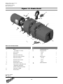
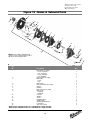
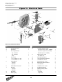
1
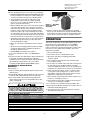
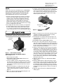
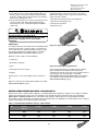
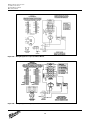
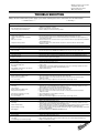
OPERATOR’S
MANUAL
ELECTRIC CHAIN HOIST
Catalog No.
9560
9561
9562
Rated Load
1/2 Ton
9565
9566
9567
9568
1 Ton
9570
9571
9572
9573
2 Ton
The equipment described and illustrated in these
instructions is intended for industrial use only and
should not be used to lift, support or otherwise
transport people.
Follow all instructions and warnings for
inspecting, maintaining and operating this hoist.
The use of any hoist presents some risk of personal injury
or property damage. That risk is greatly increased if proper
instructions and warnings are not followed. Before using this
hoist, each operator should become thoroughly familiar with
all warnings, instructions, and recommendations in this
manual. Retain this manual for future reference and use.
Forward this manual to the hoist operator.
Failure to operate the equipment as directed in the manual
may cause injury.
Before using the hoist, fill in the information below. Model and
serial numbers are stamped into the aluminum hoist housing.
Model Number
Serial Number
Purchase Date
Milwaukee Electric Tool Corporation
13135 West Lisbon Road
Brookfield, Wisconsin 53005
TEL: (800) 729-3878
20. NOT allow the load chain or hook to be touched by a live
welding electrode.
21. NOT remove or obscure the warnings on the hoist.
22. NOT operate a hoist on which the safety placards or decals
are missing or illegible.
23. NOT operate a hoist unless it has been securely attached to
a suitable support.
24. NOT operate a hoist unless load slings or other approved
single attachments are properly sized and seated in the hook
saddle.
25. Take up slack carefully - make sure load is balanced and load
holding action is secure before continuing.
26. Shut down a hoist that malfunctions or performs unusually
and report such malfunction.
27. Make sure hoist limit switches function properly.
28. Warn personnel of an approaching load.
SAFETY PRECAUTIONS
Each MILWAUKEE Electric Chain Hoist is built in accordance with
the specifications contained herein and at the time of manufacture
complies with our interpretation of applicable sections of
*American Society of Mechanical Engineers Code (ASME)
B30.16 “Overhead Hoists,” the National Electrical Code
(ANSI/NFPA 70) and the Occupational Safety and Health Act
(OSHA). Since OSHA states the National Electrical Code applies
to all electric hoists, installers are required to provide current
overload protection and grounding on the branch circuit section in
keeping with the code. Check each installation for compliance with
the application, operation and maintenance sections of these
articles.
*Copies of this standard can be obtained from ASME Order
Department, 22 Law Drive, Box 2300, Fairfield, NJ 07007-2300,
U.S.A.
Improper operation of a hoist can create a potentially
hazardous situation which, if not avoided, could result
in minor or moderate injury. To avoid such a potentially
hazardous situation, THE OPERATOR SHALL:
Improper operation of a hoist can create a potentially
hazardous situation which, if not avoided, could result
in death or serious injury. To avoid such a potentially
hazardous situation, THE OPERATOR SHALL:
1. Maintain firm footing or be otherwise secured when operating
the hoist.
2. Check brake function by tensioning the hoist prior to each
lift operation.
3. Use hook latches. Latches are to retain slings, chains, etc.
under slack conditions only.
4. Make sure the hook latches are closed and not supporting
any parts of the load.
5. Make sure the load is free to move and will clear all
obstructions.
6. Avoid swinging the load or hook.
7. Make sure hook travel is in the same direction as shown on
the controls.
8. Inspect the hoist regularly, replace damaged or worn parts,
and keep appropriate records of maintenance.
9. Use MILWAUKEE recommended parts when repairing the
unit.
10. Lubricate load chain per hoist manufacturer’s
recommendations.
11. NOT use the hoist’s overload limiting clutch to measure load.
12. NOT use limit switches as routine operating stops. They are
emergency devices only.
13. NOT allow your attention to be diverted from operating
the hoist.
14. NOT allow the hoist to be subjected to sharp contact with
other hoists, structures, or objects through misuse.
15. NOT adjust or repair the hoist unless qualified to perform
such adjustments or repairs.
1. NOT operate a damaged, malfunctioning or unusually
performing hoist.
2. NOT operate the hoist until you have thoroughly read and
understood the manufacturer’s Operating and Maintenance
Instructions or Manuals.
3. NOT operate a hoist which has been modified without the
manufacturer’s approval or without certification that it is in
conformity with ANSI/ASME B30 volumes.
4. NOT lift more than rated load for the hoist.
5. NOT use hoist with twisted, kinked, damaged, or worn load
chain.
6. NOT use the hoist to lift, support, or transport people.
7. NOT lift loads over people.
8. NOT operate a hoist unless all persons are and remain clear
of the supported load.
9. NOT operate unless load is centered under hoist.
10. NOT attempt to lengthen the load chain or repair damaged
load chain.
11. Protect the hoist’s load chain from weld splatter or other
damaging contaminants.
12. NOT operate hoist when it is restricted from forming a
straight line from hook to hook in the direction of loading.
13. NOT use load chain as a sling, or wrap chain around load.
14. NOT apply the load to the tip of the hook or to the hook latch.
15. NOT apply load unless load chain is properly seated in the
chain sprocket(s).
16. NOT apply load if bearing prevents equal loading on all load
supporting chains.
17. NOT operate beyond the limits of the load chain travel.
18. NOT leave load supported by the hoist unattended unless
specific precautions have been taken.
19. NOT allow the load chain or hook to be used as an electrical
or welding ground.
2
Milwaukee Electric Tool Corporation
13135 West Lisbon Road
Brookfield, Wisconsin 53005
TEL: (800) 729-3878
TABLE OF CONTENTS
Safety Precautions ......................................................................................................................................................................2
Hoist Specifications.....................................................................................................................................................................3
Application Information ...............................................................................................................................................................4
Safety Information .......................................................................................................................................................................4
Installation ...................................................................................................................................................................................4
Operation ....................................................................................................................................................................................5
Maintenance ...............................................................................................................................................................................6
Wiring Diagrams .......................................................................................................................................................................12
Trouble Shooting .......................................................................................................................................................................13
Inspection and Maintenance Check List ...................................................................................................................................14
Recommended Lubrication Schedule.......................................................................................................................................15
Replacement Parts List.............................................................................................................................................................16
Parts Depot & Warranty Repair Centers...................................................................................................................................28
Warranty .....................................................................................................................................................................Back Cover
HOIST SPECIFICATIONS
MILWAUKEE Electric Chain Hoists are rugged, portable hoists
that provide quick, precise lifting. The hoists are constructed of
tough, but lightweight, die cast aluminum alloy housings. An oil
bath transmission, equipped with heat-treated, alloy steel
gears and an overload limiting clutch, provides smooth and
reliable operation.
Other features that ensure the safe operation of MILWAUKEE
Electric Chain Hoists include a magnetic disc brake that
delivers sure stopping and secure holding of the load.
Adjustable upper and lower limit switches regulate the load
travel. As a standard, hooks are supplied with safety latches.
For additional safety, a chain stop is attached to the slack end
of the load chain.
With a pushbutton station that fits comfortably in one hand, the
operator can safely control the hoist while the other hand is
free to guide the load. The electrical controls, which are readily
accessed under the electrical cover, utilize quick connections
for easy voltage conversions and a 24V control circuit for
added safety.
MILWAUKEE Electric Chain Hoists are designed and tested in
accordance with the American Society of Mechanical
Engineers Code B30.16, “Safety Standard for Overhead
Hoists.” Hoists are built in compliance with CSA, file number
LR 44484. Made in U.S.A.
Table 1 - Hoist Specifications
Model
Capacity
(tons)
Lifting
Speed
(fpm)
Lift
(ft)
9560
1/2
16
10
9561
1/2
16
15
9562
1/2
16
20
9565
1
16
9567
1
16
9568
1
9566
Control Cord
Length
(ft)
Full Load
Motor Amps *
Phase
115/230V
7.6/3.8
Single
115/230V
7.6/3.8
Single
1/2
115/230V
7.6/3.8
Single
Single-chained
1
115/230V
14/7**
Single
Single-chained
1
115/230V
14/7**
Single
16
Single-chained
1
115/230V
14/7**
Single
6
Single-chained
1
230/460V
3.2/1.6
Three
10
6
Double-chained
1
115/230V
14/7**
Single
15
11
Double-chained
1
115/230V
14/7**
Single
8
20
16
Double-chained
1
115/230V
14/7**
Single
8
10
6
Double-chained
1
230/460V
3.2/1.6
Three
Reeving
HP
Voltage
(AC)
6
Single-chained
1/2
11
Single-chained
1/2
16
Single-chained
10
6
15
11
16
20
1
16
10
9570
2
8
9572
2
8
9573
2
9571
2
* At full load, it is not unusual for the hoist to draw in excess of
the values listed when lifting. It is critical to ensure that the
voltage at the hoist contactor does not drop below 10% of
the nominal voltage of the hoist while it is lifting a load. Low
voltage will result in higher amp draw, damage to the hoist,
and potential fire hazards. MILWAUKEE is not responsible
for any damages caused by an inadequate power source.
**The 1HP, 115/230V models must have a dedicated power
circuit rated for at least 20A, 125V when they are wired for
115V. It is not unusual for these models to draw up to 20
amps at 115V when lifting at rated capacity. Refer to
Table 3 before installation.
3
Milwaukee Electric Tool Corporation
13135 West Lisbon Road
Brookfield, Wisconsin 53005
TEL: (800) 729-3878
APPLICATION INFORMATION
Always disconnect the power source before working
on or near a hoist or its connected load. If the power
disconnect point is out of sight, lock it in the open
position and tag to prevent unexpected application
of power.
This hoist is intended for general industrial use for lifting and
transporting freely suspended material loads within its rated
capacity. MILWAUKEE cannot be responsible for applications
other than those for which MILWAUKEE equipment is
recommended. Prior to installation and operation, we caution
the user to review his application for abnormal environmental
or handling conditions and to observe the applicable
recommendations as follows:
4. Protect the power cable and control cable from coming in
contact with sharp objects.
5. Do not kink power cable and control cable and never allow
the cable to come in contact with oil, grease, hot surfaces,
or chemicals.
6. Make certain that the power source conforms to the
requirements of your equipment.
7. Inspect the unit daily before operating hoist.
8. Cluttered areas and benches invite accidents.
9. The operator should not engage in any practice which will
divert his attention while operating the hoist.
10. Before using the hoist, the operator should be certain that
all personnel are clear.
11. Do not operate hoist with loads exceeding its rated capacity.
12. Supporting frames or beams used as a hoist hanger must
have a greater load capacity than the hoist.
13. Do not attempt to operate hoist beyond normal maximum
lift range.
14. Align hoist for a straight line pull. Avoid side pull or end pull.
15. Do not operate hoist with twisted or damaged chain.
16. Do not operate a damaged or malfunctioning hoist until
necessary adjustments or repairs have been made.
17. Do not use hoist to lift people or to carry loads over people.
18. Do not leave a load suspended in the air unattended.
19. Always remove load before making repairs.
20. Do not remove or obscure capacity or warning decals.
ADVERSE ENVIRONMENTAL CONDITIONS
Do not use the hoist in areas containing flammable vapors,
liquids, gases or any combustible dusts or fibers. Refer to
Article 500 of the National Electrical Code. Do not use this
hoist in highly corrosive, abrasive or wet environments. Do not
use this hoist in applications involving extended exposure to
ambient temperatures below -10°F or above 130°F.
LIFTING OF HAZARDOUS LOADS
This hoist is not recommended for use in lifting or transporting
hazardous loads or materials which could cause widespread
damage if dropped. The lifting of loads which could explode or
create chemical or radioactive contamination if dropped
requires fail-safe redundant supporting devices which are not
incorporated into this hoist.
LIFTING OF GUIDED LOADS
This hoist is not recommended for use in the lifting of guided
loads, including dumbwaiters and elevators. Such applications
require additional protective devices which are not
incorporated into this hoist. For such applications, refer to the
requirements of applicable state and local codes, and the
American National Safety Code for elevators, dumbwaiters,
escalators and moving walks (ASME A17.1).
INSTALLATION
1. Before installing the hoist, check the following:
a. Make sure all supporting structures and attaching devices
are strong enough to hold your intended loads. If in doubt,
consult a qualified structural engineer.
b. Provide proper branch circuit protection for the hoist as
recommended in the National Electrical Code.
c. The power supply should be within plus or minus 10% of
the voltage specified on the motor nameplate. It is critical
to use adequate sized power cables, especially with
1-phase hoists (See Table 3). Be sure dual voltage hoists
are connected or wired to correspond with your power
supply (See WIRING, page 9).
d. Installation area must provide operating conditions for the
operator including sufficient room for the operator and
other personnel to stand clear of the load at all times.
e. For installations where the slack chain hanging from the
unit may be objectionable or hazardous, the use of a
chain container is recommended. See INSTALLATION OF
CHAIN CONTAINER ASSEMBLY.
Failure to comply with Safety Precautions outlined
throughout this manual can result in serious injuries
or death. Before using this hoist, each operator
should become thoroughly familiar with all warnings,
instructions and recommendations in this manual.
SAFETY INFORMATION
1. Follow all local electrical and safety codes, as well as the
National Electrical Code (NEC) and the Occupational
Safety and Health Act (OSHA) in the United States.
2. Hoist must be securely and adequately grounded. The hoist
power cable is provided with an additional lead (green) for
grounding purposes.
3. Be careful when touching the exterior of an operating
motor; it may be hot enough to be painful or cause injury.
With modern motors this condition is normal if operated at
rated load and voltage (modern motors are built to operate
at higher temperatures).
4
Milwaukee Electric Tool Corporation
13135 West Lisbon Road
Brookfield, Wisconsin 53005
TEL: (800) 729-3878
2. Before operating the hoist, be sure to observe the following:
a. ALWAYS DISCONNECT HOIST FROM POWER SUPPLY
before removing the electrical cover or when making any
electrical connection in the hoist or pushbutton station.
b. The ground wire (green colored) of the power cable
should always be connected to a suitable ground by
means of a screw or clamp. An alligator clip does not
make a safe ground connection.
c. When installing a three-phase hoist, make only temporary
connections at the power source. Push the “UP” button
and observe the direction of the load block. If it raises, the
phasing is correct and permanent connections may be
made at the power source. If the load block lowers when
the “UP” button is pushed, release the button immediately
since the limit switches will not operate to protect the hoist
from over-travel. Reverse any two wires (except the green
ground wire) at the power source to correct the load hook
direction (phasing). Do not change connections in the
hoist or pushbutton assembly.
d. Make sure load chain is not twisted as it travels into the
hoist.
e. Operate hoist in a hanging position only. Hoist should be
permitted to align itself for a straight line pull. Do not
attempt to pull around corners.
f. Read ASME-B30.16 Safety Code for Hoists.
3. If necessary, lubricate the chain, see LUBRICATION,
page 9.
4. Check the function of the limit switches. Before placing hoist
in operation, check limit switch adjustment. Operate
pushbutton until near stop point and inch into stop limit both
top and bottom. If either switch is not correct, adjust
according to LIMIT SWITCH ADJUSTMENT, page 8.
Retainer
Clip
Attachment
Pin
Figure 1 — Installing
Chain Container
Assembly
4. Feed the remainder of chain into container by operating
hoist in the “UP” direction to the top limit. This will permit the
chain to pile freely and prevent the chain from kinking, which
may occur if the chain is placed in the container by hand.
OPERATION
This hoist is designed for safe operation within the limits of its
rated capacity. It is controlled with the “UP” and “DOWN”
buttons of the pushbutton station. There are many safety
features to protect the operator from injury due to failure of the
hoist. Here are some points which should be observed to
maintain safe operation.
1. Do not overload the hoist.
2. Do not make extreme side pulls with the hoist.
3. Operate the hoist only in a hanging position with
adequate support.
4. Do not “sling” the load hook and chain around the load.
Use an approved sling.
5. Be sure there are no twists in the load chain as it travels into
the hoist housing. This condition should be constantly
checked on double chain hoists because it is possible for the
load block to be “capsized” or turned over one or more times.
6. Before raising a load, always check to see that it is held
securely in the hook or sling chains, etc. Raise the load
only until the load chain is taut and then double check the
rigging before continuing to raise the load.
7. Do not stand beneath a load! Do not move a load in such a
manner as to endanger personnel.
8. Do not lower into areas where visibility is obscured unless
someone else is guiding the operation.
9. Use common sense at all times when operating a hoist.
10. Do not operate if direction of hook travel is not the same as
indicated on button being pushed.
11. Do not operate unless hook travel limit devices function.
Test without load each shift.
Installation of Standard Chain
Containers
Refer to Figure 1.
1. Remove retaining clip and attachment pin and let the slack
chain hang free.
2. Run load hook down to its lowest position. Place the slack end
of chain in chain container. Do not remove the chain stop.
3. Place chain container flush against housing with chain
stripper between top lugs. Insert long attachment pin and
replace retaining clip.
Do not allow load to come in contact with the chain
container. If this situation exists reset the “UP” limit
switch so that the hook block stops below the chain
container (See LIMIT SWITCH ADJUSTMENT, page 8).
Table 2 - Optional Chain Container
Standard
Lifts
(ft)
Chain Container
Required
Shipping
Weight
(lbs)
Width
10, 15, & 20
48-12-0116
3
3
6½
11½
2 Ton
10
48-12-0116
3
3
6½
11½
2 Ton
15
48-12-0117
4
3
6½
18½
2 Ton
20
48-12-0118
5
6
6½
27
Hoist
Capacity
1/2 & 1 Ton
5
Dimensions in Inches
Length
Depth
Milwaukee Electric Tool Corporation
13135 West Lisbon Road
Brookfield, Wisconsin 53005
TEL: (800) 729-3878
LOWERING WITHOUT POWER
If the power fails with a load suspended, the hoist will
automatically stop. In an emergency the load can be lowered
without power as follows:
Do not use hoist to lift, support or otherwise
transport people.
12. Do not operate when hoist is not centered over load.
13. Do not operate if chain is not seated properly in sprockets
or sheave grooves.
14. Do not operate damaged or malfunctioning hoist.
1. DISCONNECT HOIST FROM POWER SUPPLY AND
REMOVE ELECTRICAL COVER.
2. Open disc brake manually by using two screwdriver blades,
one on each side of the brake at a point close to the brake
spring posts. Apply pressure to the underside of the
armature plate (points “X”, Figure 5, page 9) to close the
solenoid and release the brake.
OVERLOAD LIMITING PROTECTION
This hoist is equipped with a factory-calibrated overload
limiting clutch that will permit the lifting of loads within its rated
capacity, but will prevent the lifting of damaging overloads while
the hoist is being operated. If the load being lifted exceeds the
lifting capability of the overload clutch, the hoist motor will
continue to run, causing overheating of both the clutch and
hoist motor. This condition should be avoided by immediately
releasing the “UP” button and reducing the load to within the
rated capacity of the hoist. See GEARING, page 10, for
additional instructions on this device.
Do not allow screw driver blades to touch rotating
friction disc “C”.
Do not allow the load to descend rapidly. This causes
the motor to race and serious damage may result.
3. Use several quick releases instead of holding brake open
continuously. Do not exceed normal lowering speed.
The overload limiting clutch is an emergency
protective device and should not be used to measure
the maximum load to be lifted, or to sense the
overload imposed by a constrained load. While the
overload limiting clutch will protect the hoist from
damaging overloads, it will not ensure that a load is
within the rated capacity of the hoist.
HOOKS
Refer to Figure 2.
1. Inspect hooks once daily for cracking, extreme wear or
spreading. Replace hooks showing any of these signs. If the
throat openings are spread wider than the maximum
permissible 15% increase listed here, the hooks have been
overstressed and must be replaced. Any hook that is bent or
twisted more than 10° from the plane of an unbent hook
must also be replaced.
2. The hook latches should be inspected to ensure that they
close the hook throat opening in a secure manner when a
load is applied. Inspect the hook shank and nut for any
stripping of the threads or other damage. The hook nut should
be fully restrained by the retaining pin.
3. In addition to above, load hooks should be inspected for
cracks by the magnetic particle, dye penetrant or other
suitable crack testing inspection method. This should be
done at least once a year.
MAINTENANCE
INSPECTIONS
A planned inspection routine should be established for this
hoist based upon frequency of use, severity of use, and
environmental conditions, (Reference ASME Standard
B30.16). Some inspections should be made frequently (daily to
monthly) and others periodically (monthly to yearly). It is
strongly recommended that an Inspection and Maintenance
Check List and an Inspector’s Report, similar to those shown in
Figures 10A and 10B, be used and filed for reference. All
inspections should be performed or overseen by a designated
inspector. Special inspections should be made following any
significant repairs or any operating occurrence leading one to
Figure 2 — Hook
suspect that the hoist’s capability may have been impaired.
Inspection
X
“X” Dimension*
Hoist
Capacity
1 Ton & Under
2 Ton
Top
Hook
Bottom
Hook
111/32"
111/32"
17/32"
111/32"
(*) Maximum permissible throat opening of hook.
6
Milwaukee Electric Tool Corporation
13135 West Lisbon Road
Brookfield, Wisconsin 53005
TEL: (800) 729-3878
6. Using the “C” link, attach the new chain to the load end of
the old chain. Be sure that the welds of the upstanding links
of the new chain will face outward from the load sheave.
The end links must be oriented for attachment to the deadend screw and the chain support (double-chained only)
without any twist in the chain.
CHAIN
Chain is to be kept clean and lubricated (See LUBRICATION,
page 9). Visually check chain every time hoist is used. Hoist
must not be operated when chain is twisted or kinked. An
important phase of hoist maintenance is chain inspection.
Check individual links and check for chain elongation.
1. Check the chain for overall wear or stretch by selecting an
unworn, unstretched length of chain (at the slack end for
example). Let the chain hang vertically with a light load
(about 20 pounds) on the chain to pull it taut. Use a large
caliper to measure the outside length of a convenient
number of links (about 12"). Measure the same number of
links in a used section of chain and calculate the percentage
increase in length of the worn chain.
2. If the length of the worn chain is more than 1½% longer than
the unused chain (0.015" per inch of chain measured), then
the chain should be replaced. If the chain is worn less than
1½%, check it at several more places along its length. If any
section is worn more than 1½%, the chain should be replaced.
Double-Chain
Only
Figure 4 — Chain Replacement
Diagram
7. With the electrical cover off, connect the hoist to the power
supply. Be sure that the green ground wire is properly
grounded (See INSTALLATION, page 4).
8. Carefully jog the “UP” button and run the joined pieces of
chain into the hoist until about 15" of the new chain comes
out the other side.
9. DISCONNECT HOIST FROM POWER SUPPLY.
10. Remove the “C” link and the old chain. Remove the chain
stop from the old chain by prying off its retaining ring with a
flathead screwdriver. If attached, remove the old chain from
the side of the hoist by removing the dead-end screw and
washers (note placement of washers).
11. Attach the chain stop to the slack end of the new chain by
capturing the 12th link with the two stop halves positioned
with their tapered ends pointing towards the hoist. Slide the
sleeve over the halves and attach the retaining ring. If you
are not using a chain container, attach the slack end of the
new chain to the side of the hoist using the dead-end screw
and washers. With factory supplied hardware there should
be six washers between the hoist and chain link and two
washers between the chain link and screw head. DO NOT
allow twists in the chain.
12. Adjust the lower limit switch (See ADJUSTING LOWER
LIMIT, page 8).
13. Attach the bottom block on single-chained hoists using a
new load block screw (See Figure 20). On double-chained
hoists, feed the chain through the load block (welds of the
upstanding links will be in towards the sheave) and fasten
the end of the chain to the chain support using a new chain
support pin (See Figure 20). Be sure there are no twists in
the chain.
14. Adjust the upper limit switch (See ADJUSTING UPPER
LIMIT, page 8).
The chain used on this hoist has very carefully
controlled dimensions and has been heat treated. Do
not attempt to substitute other manufacturer’s chain.
Silver Nut
(Down)
Gold Nut
(Up)
Spring
Guide
Plate
Figure 3 — Limit Switch Assembly
Chain Replacement with Chain in Hoist
Refer to Figures 3 & 4.
1. Run hook up to its top limit.
2. DISCONNECT HOIST FROM POWER SUPPLY and
remove the electrical cover.
3. Using a screwdriver, pry the spring guide plate out of the
slots in the limit switch nuts (See Figure 3). Turn the slotted
nut nearest you, the gold nut, back to about the center of
the threaded screw. Do not disconnect the wires from the
limit switches.
4. Remove the load block assembly from the old chain. On
double-chained hoists detach the chain from the chain
support and pull it through the load block assembly (See
Figure 4).
5. Make a “C” shaped chain link by grinding through the end
link on the load end of the old chain.
7
Milwaukee Electric Tool Corporation
13135 West Lisbon Road
Brookfield, Wisconsin 53005
TEL: (800) 729-3878
2. DISCONNECT HOIST FROM POWER SUPPLY and
remove the electrical cover.
3. With a screwdriver, pry the spring guide plate out of the slots
in the limit switch nuts.
4. Turn the slotted gold nut toward its limit switch until the
switch “clicks” then turn two slots farther. Release the spring
guide plate and be sure it slips back into the slots in both
limit switch nuts. Do not disturb the silver slotted nut if it has
been set previously.
Adjusting Lower Limit (Silver Nut)
Refer to Figure 3.
Chain Replacement with No Chain in Hoist
Refer to Figures 4 and 5.
1. DISCONNECT HOIST FROM POWER SUPPLY and move
hoist to a work table. Remove the electrical cover, electrical
panel and the electric brake assembly.
2. Detach the chain stripper from the bottom of the hoist.
3. Insert the new chain between the load sheave and the chain
guide. Feed the chain into the hoist by manually turning the
brake hub. Allow about 15" of chain below the hoist on the
slack end. Be sure the welds of the upstanding links are out
away from the load sheave and that proper orientation is
observed for attachment of the slack end. Also be sure the
load hook assembly (if already attached to the chain) is
toward the center of the hoist or to your right looking from
the transmission end.
1. Suspend the hoist. Carefully lower the load block to a point
where the slack-end loop of the chain hangs down 6" or
more from the hoist housing (or the limit desired in any
particular application allowing the minimum 6"). There
should be a minimum clearance of 1½" between the chain
stop and the bottom of the hoist.
2. DISCONNECT HOIST FROM POWER SUPPLY and
remove the electrical cover.
3. With a screwdriver, pry the spring guide plate out of the slots
in the limit switch nuts.
4. Turn the slotted silver nut toward its limit switch until the
switch “clicks,” then turn two slots farther. Release the spring
guide plate and be sure it slips back in the slots in both limit
switch nuts. Do not disturb the gold slotted nut if it has been
set previously.
Check Both Upper and Lower Limits
1. Connect the hoist to the power supply. Be sure the green
ground wire is properly grounded .
2. Check load hook direction (See INSTALLATION 2-c, page 5).
3. Carefully raise load block to upper limit and observe if it
stops automatically at desired level. Do not allow load block
to run into hoist housing — this will damage the hoist.
Maintain a minimum clearance of 2" from the hoist housing
and the top of the load block on single-chained models and
1" from the chain support to the top of the load block on
double-chained models.
4. Carefully lower load block to lower limit and observe if it
stops automatically at the desired level. Do not allow slackend loop of chain to become taut against hoist housing. This
will damage the hoist. There should be a minimum clearance
of 1½" between the chain stop and the bottom of the hoist.
5. If upper and lower limits operate satisfactorily, hoist is ready
for use. If they are not as desired, repeat adjustment.
There are wires running through the hoist. Carefully
ease the hoist sections apart. Do not jerk them apart.
4. Reinstall the chain stripper (with the chain anchor on doublechained hoists, See Figure 4) observing proper chain
alignment and avoiding any twist in the chain.
5. Follow steps 11 through 14 in previous section, CHAIN
REPLACEMENT WITH CHAIN IN HOIST, to complete the
chain replacement procedure.
NOTE: Inspect chain guides and load sheave for wear,
replace as needed.
LIMIT SWITCH ADJUSTMENT
IMPORTANT: Before placing hoist in operation, check the limit
switch adjustment. Limit switches are provided to protect the
hoist against damage resulting from overtravel or to allow
setting the hook travel within the factory-set limits of travel. For
easy identification and association with the proper direction of
travel, the upper and lower limit switch adjusting nuts are colorcoded gold and silver respectively. Each limit nut has 10 slots
for fine adjustment, and the increment of adjustment is such
that one slot is equivalent to approximately one link of chain
travel. Movement of the limit switch nuts toward or away from
each other increases or decreases the hook travel respectively.
Care should be exercised when adjusting either limit of travel.
BRAKE
If the wires running to the limit switches are ever
disconnected for any purpose, be sure to replace
wires in accordance with the correct wiring diagram
(See WIRING DIAGRAMS, page 12).
Properly adjusted, this brake will release promptly when
energized. It is capable of both smoothly stopping and securely
holding the rated capacity of the hoist. If the hoist develops
either undesirable over-travel after the pushbutton is released
(this condition is most noticeable in the lowering direction) or
hesitates to lift the load promptly when the pushbutton is
depressed (this condition is most noticeable in the hoisting
direction), the brake should be adjusted.
Adjusting Upper Limit (Gold Nut)
Refer to Figure 3.
1. Suspend the hoist. For single-chained models raise the load
block until there is a minimum clearance of 2" from the hoist
housing and the top of the block. Double-chained models
require a minimum clearance of 1" from the chain support to
the top of the load block.
8
Milwaukee Electric Tool Corporation
13135 West Lisbon Road
Brookfield, Wisconsin 53005
TEL: (800) 729-3878
blocks according to the wiring diagram located inside the
electrical cover and also in Figures 9A & 9B. DO NOT move
any wires or make any changes to the electrical circuit
except at the terminal block assembly. Tug on wires to
ensure they are securely connected.
3. After converting voltage, recheck phasing and limit switch
operation (See INSTALLATION 2-c & 4, page 5).
Brake Adjustment
Refer to Figure 5.
1. DISCONNECT HOIST FROM POWER SUPPLY and
remove the electrical cover.
2. With reference to Figure 5, the gap between the brake
armature “A” and the field “B” should be checked. The
correct gap is 0.015". Adjustment should not be necessary
until gap reaches 0.040".
IMPORTANT: Always refer to the wiring diagram located on
the inside of the electrical cover or Figures 9A and 9B when
performing electrical repairs. Make sure all connections are
secure and check for damaged insulation. It is also imperative
that the power circuit has conductors of adequate size (See
Table 3).
F
B
G
E
LUBRICATION
Gap
A
X
D
Refer to Figure 11.
X
C
Proper lubrication is necessary for a long and relatively troublefree hoist operation. Refer to the following and the
RECOMMENDED LUBRICATION SCHEDULE for lubrication
points, type of lubricant, and frequency of lubrication.
H
Figure 5 — Brake Assembly
Load Chain
Clean the load chain with acid-free solvent and coat with
SAE 90 gear oil. Wipe excess oil to prevent dripping. Never
apply grease to the chain.
3. Adjust gap by adjusting the 3 locknuts “F” and checking with
a feeler gauge to be sure gap is the same on both ends of
the solenoid.
4. Adjustment is now complete and the brake properly set.
Replace the electrical cover, reconnect the power supply,
and check hoist brake action.
Gearing
The gear case of this hoist is filled at assembly with
approximately 1½ pints of SAE 90 EP gear oil. Check oil level
by removing the oil level check plug from the side of the hoist.
With the hoist hanging level, gear oil should be even with the
hole. Change oil periodically depending on the severity of the
application and the environmental conditions (at least every
200 hours of run time).
Bearings
Be sure the bottom of the armature does not bear
against the splined adapter “H”. As adjustments are
made, the built-in clearance will be reduced. When
this clearance is gone REPLACE BRAKE DISCS.
Minimum allowable disc thickness is .162". See
Figure 15 for further illustration.
All bearings except hook and idler sheave bearings are
lubricated at the factory and should not require additional
lubrication. Noisy or worn bearings should be replaced.
Limit Switch Shaft
HOIST CONTROLS
Remove any dirt accumulation and spray with a general
purpose lubricant.
Both the pushbutton and the reversing contactor are
mechanically interlocked to prevent shorting the circuit and
causing serious damage. As part of maintenance, always
check for proper closure of contact points as well as for burned
contacts. If replacement is necessary, see Figures 16 & 18 for
replacement parts.
Hook Bearing
Apply a few drops of SAE 30 gear or motor oil around the edge
of the bearing.
Idler Sheave Bearing (Bushing)
WIRING
Disassemble load block and apply a light coat of NLGI #2
grease, or equivalent, inside of bearing.
Refer to Figures 9A and 9B
MILWAUKEE Electric Chain Hoists, which are available for
115/230V or 230/460V, are shipped wired for 115V and 460V
respectively. Conversion of dual voltage hoists to either the
higher or lower voltage can be done simply and quickly as
follows:
HOIST REPAIRS
NOTE: If you do not have an experienced mechanic to do your
repair work, we recommend that you send your hoist to an
approved service station for repairs. Use authorized repair
parts only.
1. DISCONNECT HOIST FROM POWER SUPPLY and
remove the electrical cover.
2. Each dual-voltage hoist has a terminal block assembly for
the interconnection of the electrical components of the hoist.
To convert voltage, reconnect the leads to the terminal
1. For major repairs or when the hoist is to be sectioned in the
suspension area, it will be necessary to move the hoist to a
workbench or table.
9
Milwaukee Electric Tool Corporation
13135 West Lisbon Road
Brookfield, Wisconsin 53005
TEL: (800) 729-3878
Motor
Refer to Figures 12, 13 and 14
Remove load and disconnect hoist from power supply
before starting to do any repairs or to take any
sections apart.
The hoist motor is located on the opposite end to that of the
electrical parts, but the two are tied together with electrical
leads running through the housing.
1. If it is necessary to replace or repair the motor,
DISCONNECT THE HOIST FROM THE POWER SUPPLY
and remove the electrical cover.
2. Loosen the screw clamps on the terminal blocks and
reversing contactor to disconnect the motor leads (See
Figure 16).
3. Remove the four motor mounting bolts attaching the motor
to the housing. It will come loose at the motor coupling.
4. Inspect the motor coupling, motor shaft and all the bearings.
Replace as necessary.
5. Install new or repaired motor according to the wiring diagram
located inside the electrical cover or Figures 9A and 9B.
Gearing
2. For repairs which can be done by removing the electrical
cover only, the hoist need not be moved. Lowering the hoist
to a convenient working level is desirable.
The following repair instructions will help you in understanding
repair procedures, when related to the Replacement Parts List
starting on page 16. For clarity these are broken down into
areas.
Electrical Parts and Brake
Refer to Figures 9A, 9B & 16.
1. Remove the cover to access the controls. Single-phase
models also have a starting switch and capacitor mounted on
the motor as shown in Figure 13. The terminal blocks and end
clamps snap off of the rails on the plate using a small
screwdriver. DO NOT SLIDE THE END CLAMPS.
The reversing contactor can be slid off the rail, but it must be
snapped on. Where the contactor fits the rail, one side has
springs or pads that apply pressure against the edge of the
rail. By pressing against that side at the base of the contactor,
you can snap the part on or off using a rotating action. Note
the numbers that label the terminals on the contactor and
orient the part as shown in Figures 9A & 9B. Single-phase
contactors have a small jumper that is not present on the
3-phase (note the 3 and 5 terminals on the reversing
contactor in Figure 9A).
2. Remove the electrical panel by removing the stand-off
screws (See Figure 16). The limit switch and brake are now
accessible as shown in Figure 6.
3. Remove the transformer bolted to the back of the panel plate
if it requires replacement.
4. Refer to Figure 15 to disassemble the brake. See BRAKE
ADJUSTMENT on page 9 to properly set the brake.
5. Refer to Figure 17 to disassemble the limit switch.
See LIMIT SWITCH ADJUSTMENT on page 8 to properly
set the upper and lower limits of travel.
6. Refer to Figure 18 for repairs on the pushbutton station. Also
refer to the wiring diagram inside the electrical cover or
Figures 9A and 9B for wiring instructions.
Use the Replacement Parts List for Basic Hoist and
Transmission Parts to help in repairs on gearing (See Figures
12 and 19). As disassembly is extensive for gearing,
disconnect hoist and move to a workbench.
1. Remove electrical cover.
2. Remove electrical panel.
3. Remove brake assembly and limit switch assembly.
4. Drain oil from transmission.
Do not disassemble or readjust clutch, or replace with
a clutch assembly from another hoist. Doing so will
void the warranty and may create an unsafe condition.
If replacement is needed due to wear or loss of
adjustment, always use a new clutch assembly.
5. Remove four screws attaching transmission cover to gear
housing and remove transmission cover. Limit switch drive
shaft will come along with the cover.
6. Inspect gears for broken or severely worn teeth and inspect
all bearings. Replace as necessary. The overload slip clutch
is factory calibrated and must not be disassembled or
readjusted.
Figure 7 - Assembled Gearing
Figure 6 - Electrical Panel Removed
10
Milwaukee Electric Tool Corporation
13135 West Lisbon Road
Brookfield, Wisconsin 53005
TEL: (800) 729-3878
7. Reassemble in reverse order of disassembly making sure
gasket is in place and in good condition. Coat gasket with
Permatex® or other gasket cement. Extreme care should be
taken to avoid damage to oil seals.
8. Check all wire terminals to be sure they are properly seated
and in accordance with wiring diagram. Before placing
hoist back into service, check brake adjustment and limit
switch stops.
Periodic inspections of the top suspensions can be made
without disassembly. For more extensive inspections the lug
maybe removed as follows:
1. Disconnect the hoist and remove it to workbench.
2. Remove the lug retaining screw.
3. Remove the lug retainer.
4. Remove the lug.
Failure to follow proper lockout/tagout procedures may
present the danger of electrical shock.
TO AVOID INJURY:
Disconnect power and lockout/tagout disconnecting
means before removing cover or servicing this
equipment.
Suspension
Figure 8A - Single Chain Lug Orientation
Use Replacement Parts List for Basic Hoist and Chaining Parts
to help in repairs in this section (See Figures 12 and 20). The
hoist sections must be separated at the top hook line in order
to inspect the load sheave and chain guides. See CHAIN
REPLACEMENT WITH NO CHAIN IN HOIST, page 8.
While this section is apart, check the following:
• Load sheave
• Chain guides and plates
• Chain
Figure 8B - Double Chain Lug Orientation
Care must be taken during reassembly to have the hook in
proper orientation. Refer to figures 8A & 8B for proper
orientation. The transmission must be disassembled in order to
inspect load sheave and chain guide (see CHAIN
REPLACEMENT WITH NO CHAIN IN HOIST, page 8). When
reassembled, recheck the limit switch settings (See LIMIT
SWITCH ADJUSTMENT, page 8).
• Chain support (on 2 ton models)
• Bearings
Replace parts as necessary including screws, lockwashers,
etc.
When reassembled, recheck limit switch operation. See LIMIT
SWITCH ADJUSTMENT, page 8.
POWER CORD PRECAUTIONS WITH 1-PHASE HOISTS
Electric hoists require a sufficient power supply. It is especially important with single-phase voltage to ensure that the conductors
running to the hoist from the power source are adequate in size to handle the power requirements of the hoist. Inadequate
power cables and branch circuits will cause low voltage, high amperage, damage to the hoist, and potential fire hazards.
Such problems can be minimized by using 230V power on 115/230V hoists. The following are recommendations for the conductor
gage size depending on the length, horsepower, and voltage.
Table 3 - Recommended Conductor Sizes for 1-Phase Hoists
Maximum Length of Power Cord in Feet
HP
Voltage
(1-Phase)
1/2
115V
230V
1
115V
230V
14 AWG
12 AWG
10 AWG
8 AWG
40
200
60
330
100
520
150
810
0
120
30
190
50
310
75
490
11
Milwaukee Electric Tool Corporation
13135 West Lisbon Road
Brookfield, Wisconsin 53005
TEL: (800) 729-3878
Figure 9A — Wiring Diagram for 1-Speed, 1-Phase Models
Figure 9B — Wiring Diagram for 1-Speed, 3-Phase Models
12
Milwaukee Electric Tool Corporation
13135 West Lisbon Road
Brookfield, Wisconsin 53005
TEL: (800) 729-3878
TROUBLE SHOOTING
Always disconnect unit from the power supply system before removing hoist covers or the back cover of control station.
––– Remedy–––
––– Probable Cause –––
Hook fails to stop at end of travel
1.
Limit switch not operating
2.
3.
Brass limit switch nuts not moving on shaft
Hoist reversing contactor malfunctioning
1. Check adjustment (See LIMIT SWITCH ADJUSTMENT, page 8). Check connections against wiring diagram.
Tighten loose connections or replace.
2. Check for stripped threads or bent nut guide.
3. Remove electrical cover and check reversing contactor.
Hoist does not respond to pushbutton
1.
2.
3.
4.
Power failure in supply lines
Wrong voltage or frequency
Improper connections in hoist or pushbutton
station
Brake does not release
5.
Faulty hoist reversing contactor
1. Check circuit breakers, switches and connections in power supply lines.
2. Check voltage and frequency of power supply against the rating on the nameplate of the motor.
3. Check all connections at line connectors and on terminal block. Check terminal block on dual voltage hoists for
proper voltage connections.
4. Check connections to the solenoid coil. Check for open or short circuit. Check for proper adjustment (See BRAKE
ADJUSTMENT, page 9).
5. Check coils for open or short circuit. Check all connections in control circuit. Check for burned contacts.
Replace as needed.
Hook does not stop promptly
1.
2.
Hoist overloaded
Brake not holding
1. Reduce load to within rated capacity of hoist.
2. Check brake adjustment (See BRAKE ADJUSTMENT, page 9). It may be necessary to replace discs.
Hook moves in wrong direction
1.
2.
Three phase reversal
Improper connections
1. Reverse any two wires (except the green ground wire) at the power source (See INSTALLATION 2c, page 5).
2. Check all connections against wiring diagram.
Hoist hesitates to lift when energized
1.
2.
3.
4.
Hoist overloaded
Motor brake requires adjustment
Worn overload limiting clutch
Low voltage
5.
Faulty SINPAC® starting switch or start capacitor
(single phase hoists only)
1.
2.
3.
4.
Reduce load within rated capacity of hoist.
Check motor brake adjustment (See BRAKE ADJUSTMENT, page 9).
Replace clutch.
Determine cause of low voltage and bring up to within plus or minus 10% of the voltage specified on the motor.
Measure voltage at the hoist reversing contactor while lifting a load.
5. Replace faulty component.
Hook raises but will not lower
1.
2.
3.
“DOWN” circuit open
Broken conductor in pushbutton cable
Faulty hoist reversing contactor
4.
Loose screw clamps
1. Check circuit for loose connections. Check “DOWN” limit switch for malfunction.
2. Check each conductor in the cable. If one is broken, replace entire cable.
3. Check coils for open or short circuit. Check all connections in control circuit. Check for burned contacts.
Replace as needed.
4. Ensure that screw clamps are tightened on the terminal blocks and reversing contactor.
Hook lowers but will not raise
1.
2.
Hoist overloaded
Low voltage
3.
4.
5.
“UP” circuit open
Broken conductor in pushbutton cable
Faulty hoist reversing contactor
6.
7.
8.
Faulty capacitor (single phase hoist only)
Worn overload limiting clutch
Loose screw clamps
1. Reduce load to within rated capacity of hoist.
2. Determine cause of low voltage and bring up to within plus or minus 10% of the voltage specified on the motor.
Measure voltage at the hoist reversing contactor while lifting a load.
3. Check circuit for loose connections. Check “UP” limit switch for malfunction.
4. Check each conductor in the cable. If one is broken, replace entire cable.
5. Check coils for open or short circuit, check all connections in control circuit. Check for burned contacts.
Replace as needed.
6. Check starting capacitor on motor. Replace if necessary.
7. Replace overload clutch assembly.
8. Ensure that screw clamps are tightened on the terminal blocks and reversing contactor.
Motor overheats
1.
2.
Excessive load
Low voltage
3.
Extreme external heating
4.
Frequent starting or reversing
5.
Brake dragging
1. Reduce load to within rated capacity of hoist.
2. Determine cause of low voltage and bring up to within plus or minus 10% of the voltage specified on the motor.
Measure voltage at the hoist reversing contactor while lifting a load.
3. As the ambient temperature rises towards the 130°F limitation of the unit, frequency of the hoist operation must be
limited to avoid overheating of the motor. See ADVERSE ENVIRONMENTAL CONDITIONS, page 4.
4. Excessive inching, jogging or reversing should be avoided since this type of operation will drastically shorten the life
of motor, contactor and brake.
5. Check brake adjustment (See BRAKE ADJUSTMENT, page 9).
Lack of proper lifting speed
1.
2.
3
4.
Hoist overloaded
Brake dragging
Low voltage
Overload limiting clutch intermittently slipping
1.
2.
3.
4.
Reduce load to within rated capacity of hoist.
Check for proper brake adjustment or other defects.
Ensure that the voltage at the reversing contactor is within ±10% of the nominal voltage while lifting a load.
Replace overload clutch assembly.
13
Milwaukee Electric Tool Corporation
13135 West Lisbon Road
Brookfield, Wisconsin 53005
TEL: (800) 729-3878
TROUBLE SHOOTING (Continued)
Motor brake noise or chatter (while starting hoist)
1.
2.
Brake needs adjustment
Low voltage
1. See BRAKE ADJUSTMENT, page 9.
2. Check voltage at the hoist reversing contactor while the hoist is lifting a load. Voltage should be no less than 90% of
the voltage specified. 115 volt hoists are particularly subject to voltage drop problems due to their high current draw.
Conversion to 230 volt operation is suggested in extreme cases.
Motor brake “buzz” (anytime hoist is running)
1.
2.
Brake needs adjustment
Broken shading coil on brake frame
1. See BRAKE ADJUSTMENT, page 9.
2. Replace shading coil or complete brake frame assembly.
INSPECTION AND MAINTENANCE CHECK LIST
ELECTRIC POWERED OVERHEAD CHAIN HOIST
Type of Hoist ______________________________________________________
Capacity (Tons) ____________________________________________
Location _________________________________________________________
Original Installation Date _____________________________________
Manufacturer______________________________________________________
Manufacturer’s Serial No. ____________________________________
Item
Frequency of Inspection
Frequent
Possible Deficiencies
Periodic
Daily
Monthly
1-12 Mo.
Operating Controls
*
*
*
Any deficiency causing improper operation
Limit Switches
*
*
*
1. Any deficiency causing improper operation
2. Pitting or deterioration
Brake Mechanism
*
*
*
1. Slippage or excessive drift
2. Glazing, contamination or excessive wear
*
*
*
Excessive throat opening 15% bent or twisted more than 10
degrees, damaged hook latch, wear, chemical damage,
worn hook bearing. To find cracks, (use dye penetrant,
magnetic or other suitable detection methods)
*
*
*
Cracks, excessive wear or other damage which may impair
the strength of the lug. To find cracks, (use dye penetrant,
magnetic particle or other suitable detection methods)
*
*
*
Inadequate lubrication, excessive wear or stretch, cracked,
damaged or twisted links, corrosion or foreign substance
Hook and Suspension
Lug Connections
*
Cracks, bending, stripped threads
Pins, Bearings, Bushings
Shafts, Couplings
*
Excessive wear, corrosion, cracks, distortion
Nuts, Bolts, Rivets
*
Looseness, stripped and damaged threads, corrosion
*
Distortion, cracks, and excessive wear.
Build-up of foreign substances
*
Cracks, distortion. Excessive wear, internal build-up of
foreign substances
Wiring and Terminals
*
Fraying, defective insulation
Hoist Reversing
Contactor, other Electrical
Apparatus
*
Loose connections, burned or pitted contacts
Supporting Structure
and Trolley (if used)
*
Damage or wear which restricts ability to support
imposed loads
Nameplates, Decals,
Warning Labels
*
Missing, damaged or illegible
Hooks
Suspension Lug (if used)
Chain
Sheaves
Housings, Load Block
OK
Action
Required
NOTE: Refer to Maintenance and Inspection Sections of the Hoist-Maintenance Manual for further details.
FREQUENCY OF INSPECTION
Frequent — Indicates items requiring inspection daily to monthly. Daily inspections may be performed by the operator if properly designated.
Periodic — Indicates items requiring inspection monthly to yearly. Inspections to be performed by or under the direction of a properly designated period. The exact
period of inspection will depend on frequency and type of usage. Determination of this period will be based on the user’s experience. It is recommended
that the user begin with a monthly inspection and extend the periods to quarterly, semi-annually or annually based on user’s monthly experience.
Figure 10A — Recommended Inspection and Maintenance Check List
NOTE: This inspection and maintenance check list is in accordance with our interpretation of the requirements of the Safety
Standard for Overhead Hoists ASME B30.16. It is, however, the ultimate responsibility of the employer/user to interpret and
adhere to the applicable requirements of this safety standard.
14
Milwaukee Electric Tool Corporation
13135 West Lisbon Road
Brookfield, Wisconsin 53005
TEL: (800) 729-3878
INSPECTOR’S REPORT
ITEM
REMARKS (LIST DEFICIENCIES AND RECOMMENDED ACTION)
Inspector’s
Signature
Date
Inspected
Approved by
Date
Figure 10B — Recommended Inspector’s Report
RECOMMENDED LUBRICATION SCHEDULE*
MILWAUKEE ELECTRIC POWERED CHAIN HOIST
PAGE AND
REFERENCE NO.
COMPONENT
TYPE OF LUBRICANT
Figure 20
Ref. No. 18
Load Chain
SAE 90 gear oil
Figure 19
Gearing
SAE 90 extreme pressure gear oil
Figure 17
Ref. No. 9
Limit Switch Shaft
General purpose spray lubricant
Figure 20
Ref. No. 38, 50
Load Hook Bearing
SAE 30 gear or motor oil
Figure 20
Ref. No. 44
Idler Sheave Bearing
(Bushing) Assembly
NLGI #2 multi-purpose
lithium base grease
TYPE OF SERVICE AND
FREQUENCY OF LUBRICATION
HEAVY
NORMAL
INFREQUENT
Daily
Weekly
Monthly
At periodic inspection (See Figure 10A)
Monthly
Yearly
Yearly
Weekly
Monthly
Yearly
At periodic inspection (See Figure 10A)
NOTE: All bearings except hook and idler sheave bearings are prelubricated and sealed.
(*) This lubrication schedule is based on a hoist operating in normal environment conditions. Hoists operating in adverse
atmospheres containing excessive heat, corrosive fumes or vapors, abrasive dust, etc., should be lubricated more frequently.
Figure 11 — Recommended Lubrication Schedule
15
Milwaukee Electric Tool Corporation
13135 West Lisbon Road
Brookfield, Wisconsin 53005
TEL: (800) 729-3878
Figure 12 - Basic Hoist
12
9
11
10
2
1
2
3
4
5
6
7
14
Parts List for Basic Hoist
Ref
Description
No.
1
Motor
13
Qty
1
(See Figures 13 & 14)
8
Ref
No.
13
Description
14
Capacity Decal
MILWAUKEE Decal
Qty
2
2
Cover Screw
7
1/2 ton
1
3
Trim Cover
1
1 ton
1
4
Transmission Housing
1
2 ton
1
5
Transmission Case Gasket
1
6
Transmission Cover
1
†1/2 ton
1
7
Electrical Cover Gasket
1
†1 ton
1
8
Electrical Cover
1
†2 ton
1
9
Hook Retainer Screw
1
10
▲
▲
Top Hook Assembly with Latch
Rigid Hook (Standard)
1
† Swivel Hook (Optional Part)
1
11
Latch Kit Assembly
1
12
Hook Retainer
1
(▲ ) N o t S h ow n
(†)
Optional
16
Nylon Cover
Chain Container
1
Milwaukee Electric Tool Corporation
13135 West Lisbon Road
Brookfield, Wisconsin 53005
TEL: (800) 729-3878
Figure 13 - Hoist Motor, 1-Phase
1
8
9
‡
7
4
5
3
6
(‡) Refer to the motor nameplate for part number
voltage, full load amperage, horsepower, and
other motor information.
2
Parts List for Hoist Motor, 1-Phase
Ref.
No.
1
Description
Qty
Hoist Motor
1/2 hp, 115/230V-1Ph
1
1 hp, 115/230V-1Ph
1
2
Stator Assembly*
1
3
Rotor Assembly*
1
4
End Shield
1
5
Rear Bearing
1
6
Front Bearing
1
7
Shim Washer
1
8
Thru Bolt
4
9
#10 Spring Lockwasher
4
* Not available as an individual part.
17
Milwaukee Electric Tool Corporation
13135 West Lisbon Road
Brookfield, Wisconsin 53005
TEL: (800) 729-3878
Figure 14 - Hoist Motor, 3-Phase
1
8
9
‡
7
4
5
3
6
(‡) Refer to the motor nameplate for part number
voltage, full load amperage, horsepower, and
other motor information.
2
Parts List for Hoist Motor, 3-Phase
Ref.
No.
1
Description
Qty
Hoist Motor
1/2 hp, 230/460V-3Ph-60Hz
1
1 hp, 230/460V-3Ph-60Hz
1
2
Stator Assembly*
1
3
Rotor Assembly*
1
4
End Shield
1
5
Rear Bearing
1
6
Front Bearing
1
7
Shim washer
1
8
Thru Bolt
4
9
#10 Spring Lockwasher
4
* Not available as an individual part.
18
Milwaukee Electric Tool Corporation
13135 West Lisbon Road
Brookfield, Wisconsin 53005
TEL: (800) 729-3878
Figure 15 - Brake & Solenoid Parts
2
15
13
11
13
12
16
15
4
3
12
4
3
16
5
15
6
12
14
8
9
1
10
6
NOTE: Refer to wiring diagram inside
electrical cover of hoist or Figures 9A or
9B, when connecting any wires.
7
10
Parts List for Brake & Solenoid Parts
Ref.
No.
1
2
3
4
5
6
7
8
9
10
11
12
13
14
15
16
Description
Qty
Disc Brake Assembly*
1/2 hp, 115/230V
1 hp, 115/230V
1/2 hp, 230/460V
1 hp, 230/460V
Plate & Stud Assembly
Brake Disc
1/2 hp
1 hp
Brake Plate
Plate & Armature Assembly
Spring
Retainer
Plate & Frame Assembly
Brake Coil*
115/230V
230/460V
Locknut
Adapter
Screw
Retaining Ring
Shading Coil
Shading Coil Adhesive
Lockwasher
Spacer for 1/2 hp
* Dual-voltage 115/230V models use 115V Brake Assembly and Coil.
Dual-voltage 230/460V models use 230V Brake Assembly and Coil.
19
1
1
1
1
1
2
3
2
1
3
1
1
1
1
3
1
3
2
2
1
3
3
Milwaukee Electric Tool Corporation
13135 West Lisbon Road
Brookfield, Wisconsin 53005
TEL: (800) 729-3878
Figure 16 - Electrical Parts
8
1
7
5
6
9
20
8
19
21
12
10
18
12
13
2
15
16
14
13
14
16
17
11
18
4
3
8
Parts List for Electrical Parts
Ref
Description
No.
Qty
1
Transmission Cover
1
2
Panel Plate
1
3
Reversing Contactor
4
5
1 hp, 115/230V
1
1 hp, 230/460V
1
1/2 hp
1
Ref
No.
Description
10
15 ft Power Cord Assembly
11
115/230V, 1/2 hp (3 cond., 14 AWG)
1
115/230V, 1 hp (3 cond., 12 AWG)
1
230/460V (4 cond., 14 AWG)
1
PB & Cable Assembly
(See Figure 18)
Transformer
Qty
1
12
Panel Standoff Spacer
3
Pri.: 115/230V, Sec.: 24V
1
13
1/4" Internal-tooth Lockwasher
3
Pri.: 230/460V, Sec.: 24V
1
14
1/4-20UNC X 4" Screw
3
15
8-32UNC X 5/16" Screw
2
Terminal Block
115/230V
1
16
#8 External-tooth Lockwasher
2
230/460V
8
17
1/4" Flatwasher
1
4
18
10-24UNC X 1/2" Screw
1
19
Can Mounting Bracket
2
1
6
Terminal Block 115/230V
7
End Plate
115/230V
1
20
SINPAC Starting Switch
230/460V
1
21
Capacitor
8
End Clamp
3
1 hp motor
1
9
Marking Strip
1
1/2 hp motor
1
20
®
Milwaukee Electric Tool Corporation
13135 West Lisbon Road
Brookfield, Wisconsin 53005
TEL: (800) 729-3878
Figure 17 - Limit Switch Parts
1
3
5
5
4
4
6
15
6
13
7
12
14
9
10
2
Parts List for Limit Switch Parts
Ref
Description
No.
Qty
Ref
No.
1
Transmission Cover
1
9
2
Limit Switch & Shaft Assembly
1
(Includes Items 4-12)
3
Limit Switch Bracket Assembly
1
(Includes Items 4-8)
4
Switch
2
5
6-32UNC X 1" Screw
4
6
6-32UNC Elastic Locknut
4
7
Limit Switch Bracket
1
(Includes Item 8)
8
Bushing
1
21
11
8
Description
Qty
Limit Switch Shaft
1
10
Limit Switch Nut (Silver)
1
11
Limit Switch Nut (Gold)
1
12
Retaining Ring
1
13
Insulator
1
14
Spring
1
15
10-24UNC X 1/2" Screw
2
Milwaukee Electric Tool Corporation
13135 West Lisbon Road
Brookfield, Wisconsin 53005
TEL: (800) 729-3878
Figure 18 - Pushbutton Station
1
2
3
16
4
9
10
5
11
4
8
13
14
15
12
4
6
7
22
Milwaukee Electric Tool Corporation
13135 West Lisbon Road
Brookfield, Wisconsin 53005
TEL: (800) 729-3878
Parts List for Pushbutton Station
Ref.
No.
1
Description
Qty
Pushbutton Station & Control Cable Assembly
6 ft Cable Length
1
11 ft Cable Length
1
16 ft Cable Length
1
Special Drop
1
2
Pushbutton Station Assembly
3
Control Cable Assembly
1
6 ft Cable Length
1
11 ft Cable Length
1
16 ft Cable Length
1
Special Drop
1
4
Enclosure
1
5
Gasket
1
6
Contact Assembly
1
(Includes Item 7)
7
Button Assembly
1
8
Grommet
1
*
Hardware Kit
1
(Includes Items 9-16)
▲
Warning Tag
(†) Equal to cable length (pushbutton drop).
( ▲ ) Not shown.
23
1
Milwaukee Electric Tool Corporation
13135 West Lisbon Road
Brookfield, Wisconsin 53005
TEL: (800) 729-3878
Figure 19 - Transmission Parts
13
11
14
*18
15
*16
*19
9
5
14
*20
6
11
*18
21
22
4
16
23
24
17
21
16
1
3
34
2
7
10
34
8
11
25
27
26
28
32
29
12
**33
30
31
(*) NOTE: This stage of gearing is not required on 32
FPM models.
24
(**) NOTE: Orient output gear (32) with long boss
towards gear housing (2) on 1/2 ton &
under models and towards transmission
cover (3) on 1 & 2 ton models.
24
12
Milwaukee Electric Tool Corporation
13135 West Lisbon Road
Brookfield, Wisconsin 53005
TEL: (800) 729-3878
Parts List for Transmission Parts
Ref.
No.
1
Description
Qty
Sheave Housing
1
2
Transmission Gasket
1
3
Transmission Cover
1
4
Spring Washer
1
5
O-ring
1
6
Pressure Relief Fitting
1
7
Chain Guide
1
8
Oil Plug - Drain
1
9
(Includes Oil Seals)
Oil Plug - Fill
1
10
Oil Plug - Level
1
11
Oil Seal
3
12
Screw, HWH Self-threading
5
13
Motor Coupling
1
14
Bearing
2
15
Input Pinion
16
Retaining Ring
17
Brake Adapter
1
18
Bearing for 8 & 16 fpm
2
19
High Speed Pinion for 8 & 16 fpm
1
20
Intermediate Pinion
3
1/2 ton
1
1 & 2 ton
1
21
Bearing
2
22
Output Pinion
1
23
Overload Clutch Assembly
1/2 ton
1
1 & 2 ton
1
24
Retaining Ring
2
25
Bearing
1
26
Bearing
1
27
Spacer - Load Sheave
1
28
Load Sheave-9/32" Chain
1
29
Load Sheave Shaft
1
30
Stub Shaft - Limit Switch Drive
1
31
Oil Seal
1
32
Retaining Ring
1
33
Output Gear
1
34
Dowel Pin
2
*
Gear Oil
1½
pt
* Not Shown
25
Milwaukee Electric Tool Corporation
13135 West Lisbon Road
Brookfield, Wisconsin 53005
TEL: (800) 729-3878
Figure 20 - Chaining Parts
2
3
1
10
4
5
9
6
15 14
13
11
15
16
17
14
18
13
7
8
19
7
1 Ton Under Models
24
25
22
24
26
21
28
29
2-Ton Models
12
20
23
30
31
32
26
Milwaukee Electric Tool Corporation
13135 West Lisbon Road
Brookfield, Wisconsin 53005
TEL: (800) 729-3878
Parts List for Chaining Parts
Ref
Description
No.
1
Housing
Qty
Ref
No.
20
1
Description
Qty
Bottom Hook Assembly
2
Transmission Cover
1
with Latch for 1 Ton & Under
3
Electrical Cover
1
4
Anchor Pin (2 ton only)
1
5
Anchor (2 ton only)
1
22
3/8-24 Hex Locknut
2
6
Chain Stripper
1
23
Load Block Screw
2
7
Chain Stop Kit
1
24
Load Block Frame
2
(Kits include halves, sleeve and
25
Sheave Shaft Assembly
1
retaining ring)
26
Sheave Shaft
1
21
1
Bottom Block Assembly
for 2 Ton
1
8
Load Chain
•
27
Sheave & Bearing Assembly
1
9
Attachment Pin
1
28
Roll Pin
2
10
Retaining Clip
1
29
3/8-24 Hex Locknut
1
11
1/4-20UNC x 1¼"
30
Bearing
1
31
Latch Kit
1
32
Bottom Hook Assembly
Socket Head Cap Screw
12
13
1
Bottom Block Assembly
1 ton & Under
1
1/4-20UNC x 1¼"
2
with Latch for 2 Ton
Socket Head Cap Screw
14
1/4" Internal-tooth
Lockwasher
2
15
Load Block Frame
2
16
Load Block Pin
1
17
Slotted Hex Nut
1
18
Bearing
1
19
Latch Kit
1
27
1
Milwaukee Electric Tool Corporation
13135 West Lisbon Road
Brookfield, Wisconsin 53005
TEL: (800) 729-3878
NOTES
28
Milwaukee Electric Tool Corporation
13135 West Lisbon Road
Brookfield, Wisconsin 53005
TEL: (800) 729-3878
NOTES
29
Milwaukee Electric Tool Corporation
13135 West Lisbon Road
Brookfield, Wisconsin 53005
TEL: (800) 729-3878
AUTHORIZED WARRANTY REPAIR CENTERS AND PARTS DEPOTS
As a user of MILWAUKEE hoists, you are assured of reliable repair and parts services through a network of Master Parts Depots and Service
Centers that are strategically located across the United States, its territories and Canada. These facilities have been selected on the basis of
their demonstrated ability to handle all parts and repair requirements promptly and efficiently. Below is a list of the Authorized Warranty Repair
Centers and Parts Depots located in United States, its territories and Canada.
UNITED STATES
ALABAMA
**TOOL SMITH CO.
1300 4th Ave.S.
Birmingham AL 35233
(205) 323-2576 or (800) 317-8665
Fax (205) 323-9060
GEORGIA
**ACE INDUSTRIES INC.
6295 McDonough Drive
Norcross GA 30093
(770) 441-0898 or (800) 733-2231
Fax (800) 628-3648
MASSACHUSETTS
**ABEL DISTRIBUTORS INC.
50 Parker St.
Newbury Port MA 01950
(978) 463-0700
Fax (978) 463-5200
ARKANSAS
**HI-SPEED HOIST & CRANE
701 N. Maple St,
N. Little Rock AR 72114
(501) 375-9178 Fax (501) 375-4254
*GAFFEY INC.
471 Sessions St.
Marietta GA 30060
(770) 939-6443 or (800) 820-6443
Fax (770) 422-2255
**HANDLING SYSTEMS & CONVEYORS INC
10909 East Otter Creek Rd.
Mabelville AR 72103
(501) 455-5898 Fax (501) 455-6179
ILLINOIS
**INDUSTRIAL TOOL PRODUCTS
919 N. Central Ave.
Woodale IL 60191
(630) 766-4040 or (800) 525-9654
Fax (630) 766-4166
MICHIGAN
*COMMERCIAL GROUP
9955 Grand River
Detroit MI 48204
(313) 931-6100 or (800) 931-7701
Fax (313) 491-1753
ARIZONA
**MECHANICS TOOL SERVICE
1301 E. Apache Park Place
Tuscon AZ 85714
(520) 889-8484 AZ only (800) 372-6700
Fax (520) 889-6668
CALIFORNIA
**ARROW CRANE HOIST CORP.
12714 South Carmenita Road
Santa Fe Springs CA 90670
(562) 921-8328 Fax (562) 921-9307
**IDG. CALIFORNIA
6842 Walker Street
LaPalma CA 90623
(714) 994-6960 or (800) 464-5669
Fax (714) 521-0105
**CRANEWORKS, INC.
2585 Nicholson Street
San Leandro CA 94577
(510) 357-4000 Fax (510) 357-4099
**KIMMERLE BROTHERS, INC.
12060 East Florence St.
Santa Fe Springs CA 90670
(562) 946-6771 Fax (562) 944-3473
**KIMMERLE BROTHERS, INC.
226 11th St.
San Franciso CA 94103
(415) 431-1163 Fax (415) 431-1693
**KIMMERLE BROTHERS, INC.
337 “M” St.
Fresno CA 93721
(559) 233-1278 Fax (559) 233-4678
COLORADO
**CRANE REPAIR CO.
3718 Norwood Drive
Littleton CO 80125
(303) 791-7918 or (800) 878-7918
Fax (303) 791-7179
FLORIDA
**J. HERBERT CORP.
1751 S. John Young Parkway
Kissimmee FL 32741
(407) 846-0588 or (800) 255-0588
Fax (407) 846-8042
**MATERIAL HANDLING SYSTEMS
720 S.W. 4th Court
Dania FL 33004
(954) 921-1171 or (888) 424-6478
Fax (954) 921-7117
*S & K AIR POWER
Rt. 316 E., Box 1279
Mattoon IL 61938
(217) 258-8500 (IL only-800-955-8501)
Fax (217) 258-8571
**SIEVERT ELECTRIC SERVICE
1230 South Hannah
Forest Park IL 60130
(708) 771-1600 or (800) 322-9144
Fax (708) 771-3124
INDIANA
**BREHOB CORP.
1334 S. Meridian St.
Indianapolis IN 46225
(317) 231 8080 or (800) 632-4451
Fax (317) 231-8072
**MATERIALS HANDLING EQUIPMENT
7433 US 30 East
Fort Wayne IN 46803
(219) 749-0475 or (800) 443-6432
Fax (219) 749-0481
IOWA
**ALTER & SONS, INC.
514 S. Howell St.
Davenport IA 52808
(563) 323-3601 or (800) 553-1111
Fax (563) 324-0138
KENTUCKY
**ADVANCED SHERMAN
330 North Spring St.
Louisville KY 40206
(502) 896-2166 (KY only-800-633-8186)
Fax (502) 897-9837
LOUISIANA
**RENTAL SERVICE
3301 Cities Service Hwy
West Lake LA 70669
(337) 882-6011
Fax (337) 882-0527
**DRILLCO
12649 S. Choctaw Dr.
Baton Rouge LA 70815
(225) 272-8251or (800) 851-3821
Fax (800) 315-9225
30
**CONTINENTAL CRANE & SERVICE CO.
33681 Groesbeck Hwy.
Fraser Ml 48026
(586) 293-3870 Fax (586) 293-0017
**STEWART ENGINEERING & SALES
2140 Aurora Ave.
Muskegon MI 49442
(231) 767-2140 Fax (231) 767-2233
MINNESOTA
**ELECTRIC MOTOR REPAIR, INC.
2010 N. 4th St.
Minneapolis MN 55411
(612) 522-3318 or (800) 345-0198
Fax (612) 588-1617
**J & B EQUIPMENT
8200 Grand Avenue South
Bloomington MN 55420
(952) 884-2040 Fax (952) 346-1139
***PERFECTION CRANE & HOIST INC.
201 DeGraff Ave.
Swanville MN 56382
(320) 547-2401 or (800) 253-6829
Fax (800) 353-2254
**TOTAL TOOL SUPPLY
315 N. Pierce St.
St. Paul MN 55104
(952) 646-4055 or (800) 444-4899
Fax (952) 646-8610
MISSOURI
**HERTZ EQUIPMENT RENTAL & SUPPLY
800 E. 18th St.
Kansas City MO 64108
(816) 221-7788 or (800) 669-7788
Fax (816) 221-0817
**HANDLING SYSTEMS INC.
11678 Gravois Rd.
St. Louis MO 63126
(314) 842-7263 Fax (314) 842-5041
**ZELLER ELECTRIC
4250 Hoftmeister
St. Louis MO 63125
(314) 638-9641 (Outside MO (800) 530-5810)
Fax (314) 638-6318
MONTANA
**POWER SERVICE OF MONTANA, INC.
4025 1st Ave.
Billings Montana 59101
(406) 252-8114 or (800) 823-8665
Fax (406) 259-3956
Milwaukee Electric Tool Corporation
13135 West Lisbon Road
Brookfield, Wisconsin 53005
TEL: (800) 729-3878
UNITED STATES
NEW JERSEY
**SISSCO
186 Route 206 South
Hillsborough NJ 08844
(908) 359-9767 or (800) 392-0146
Fax (908) 359-9773
NEW YORK
**ABC ELECTRIC
24-25 46th Street.
Long Island City NY 11103
(718) 956-0000 or (N.Y. only-800-562-1919)
FAX (718) 956-4455
**BEATON INDUSTRIAL, INC.
6083 Trenton Rd.
Utica NY 13502
(315) 797-9346 (N.Y. only-800-724-4052)
Fax (315) 797-9321
PENNSYLVANIA (cont’d)
*KEYSTONE CRANE & HOIST CO.
861 S. Washington Road
McMurray PA 15317
(724) 746-5080 Fax (724) 746-5082
**MCDAL CORP.
475 East Church Road
King of Prussia PA 19406
(610) 277-5484 or (800) 626-2325
Fax (610) 277-4690
**MORRIS MATERIAL HANDLING
Tinicum Ind. Park Building E
10 Industrial Highway MS 80
Lester PA 19113
(800) 346-2098
Fax (610) 521-5907
UTAH
**ROCKY MOUNTAIN WIRE ROPE & RIG.
2421 South 2570 West
Salt Lake City UT 84119
(801) 972-4972 or (800) 615-3193
Fax (801) 974-0621
VIRGINIA
**FOLEY MATERIAL HANDLING CO.
11327 Va. Crane Drive
Ashland VA 23005
(804) 798-1343 Fax (804) 798-7843
WISCONSIN
**ALFERI INDUSTRIAL SALES & SERVICE
346 Smith Street
Neenah WI 54956
(920) 722-6483 Fax (920) 722-6489
**VOLLAND ELECTRIC EQUIPMENT CO.
75 Innsbruck Drive
Buffalo NY 14227
(716) 656-9900 Fax (716) 656-8899
**REPAIR UNLIMITED
1730 Rockwell Road
Abington PA 19001
(215) 657-3335 or (800) 369-5891
Fax (215) 784-0343
*LIFT INC.
6667 W. Mill Road
Milwaukee WI 53218
(414) 353-5353 or (800) 728-5438
Fax (414) 353-4444
NORTH CAROLINA
**CAROLINA HOIST
3310 E. Wendover Avenue
Greensboro NC 27405
(336) 375-6050 or (800) 326-3655
Fax (336) 375-6053
RHODE ISLAND
**MOTORS , HOIST & CONTROLS INC.
179 Railroad Street
Woonsocket RI 02895
(401) 767-4568 Fax (401) 767-4567
*TRESTER HOIST & EQUIPMENT
W136 N4863 Campbell Dr. Suite 4
Menomonee Falls WI 53051
(262) 790-0700 or (800) 234-6098
Fax (262) 790-1009
**SOUTHERN ELECTRIC SERVICE
2225 Freedom Drive
Charlotte NC 28266
(704) 372- 4832 or (800) 487-3726
Fax (704) 342-2604
SOUTH CAROLINA
**ENGINEERED SYSTEMS, INC.
1121 Duncan-Reidville Road
Duncan SC 29334
(864) 879-7438 or (800) 879-7438
Fax (864) 848-3143
OHIO
**CRANE AMERICA - H. W. HOUSE
920 Deneen Avenue
Monroe OH 45050
(513) 539-9770 or (800) 331-5326
Fax (513) 539-9577
TENNESSEE
**HOIST & CRANE CO.
2508 Perimeter Place
Nashville TN 37214
(615) 242-3383 or (888) 464-7811
Fax (615) 255- 4379
**AMERICRANE & HOIST CORP.
13224 Enterprise Avenue
Cleveland OH 44135
(216) 267-9100 or (800) 652-1932
Fax (216) 267-9131
**HI-SPEED ELECTRICAL CO.
3013 Thomas Street
Memphis TN 38127
(901) 357-6231 Fax (901) 357-6238
*SAMSEL SUPPLY CO.
1285 Old River Road
Cleveland OH 44113
(216) 241-0333 or (800) 892-8012
Fax (216) 241-3426
OKLAHOMA
**GAFFEY INC.
9655 E. 522 Road
Claremore OK 74017
(918) 343-1191 or (800) 331-3916
Fax (918) 343-7304
OREGON
**GENERAL TOOL & SUPPLY CO.
2705 N.W. Nicolai
Portland OR 97210
(503) 226-3411 or (800) 783-3411
Fax (503) 778-5518
PENNSYLVANIA
**AMERICRANE
1558 Myers Road
Indiana PA 15701
(888) 963-9900 or (724) 479-9100
**GLOBE ELECTRIC CO.
200 23rd Street
Pittsburgh PA 15215
(412) 781-2677 or (800) 850-4440
Fax (412) 781-1812
TEXAS
**ABEL EQUIPMENT CO., INC.
3710 Cavalier Drive
Garland TX 75042
(972) 272-7706 Fax (800) 272-2235
**GAFFEY, INC.
4301 Garland Drive
Ft. Worth TX 76117
(817) 281-1994 or (800) 284-4233
Fax (817) 581-7831
**GAFFEY, INC.
4003 S. County Road 1297
Odessa TX 79765
(915) 563-2897 or (800) 733-0006
Fax (915) 563-4703
**GAFFEY, INC.
1436 N. Duck Creek Road
Cleveland TX 77327
(281) 443-6690 or (800) 233-8179
Fax (281) 592-6984
**HYDRAULIC EQUIPMENT SER.
1021 N. San Jacinto Street
Houston TX 77002
(713) 228-4073 Fax (713) 228-0931
*PARTS DEPOT & REPAIR CENTERS
**PARTS DEPOT & WARRANTY REPAIR CENTER
***PARTS DEPOT
31
WARRANTY
Every MILWAUKEE hoist is thoroughly
inspected and tested before leaving the
manufacturing facilities. Should any
trouble develop, return the complete hoist
prepaid to the Factory, Branch or nearest
Authorized MILWAUKEE Service Station.
If inspection shows the trouble is caused
by defective workmanship or material, all
repairs will be made without charge and
the hoist will be returned, transportation
prepaid.
This warranty does not apply where:
(1) repairs or attempted repairs have been
made by persons other than MILWAUKEE
personnel or Authorized Service Station
Personnel;
(2) repairs are required because of normal
wear;
(3) the hoist has been abused or involved
in an accident;
(4) misuse is evident such as caused by
overloading the hoist beyond its rated
capacity;
(5) the hoist has been used after partial
failure;
(6) the hoist has been used with an
improper accessory. No other warranty,
written or verbal, is authorized.
Alterations or modifications of equipment and use of non-factory
repair parts can lead to dangerous operation and injury.
TO AVOID INJURY:
• Do not alter or modify equipment
• Do not use equipment to lift, support or otherwise transport people
• Do not suspend unattended loads over people
Milwaukee Electric Tool Corporation
13135 West Lisbon Road • Brookfield, WI, U.S.A. 53005
58-12-9575d1
04/04
Printed in USA