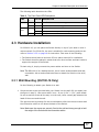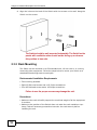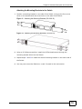
1
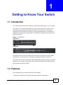
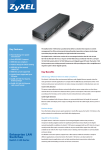
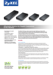
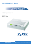
GS1100-16/GS1100-24
16-port /24-port Unmanaged Gigabit Ethernet Switch
Edition 1, 6/2010
www.zyxel.com
Copyright © 2010
ZyXEL Communications Corporation
About This User's Guide
About This User's Guide
Intended Audience
This manual is intended for people who want to configure the Switch using the
web configurator.
Documentation Feedback
Send your comments, questions or suggestions to: [email protected]
Thank you!
The Technical Writing Team, ZyXEL Communications Corp.,
6 Innovation Road II, Science-Based Industrial Park, Hsinchu, 30099, Taiwan.
Need More Help?
More help is available at www.zyxel.com.
• Download Library
Search for the latest product updates and documentation from this link. Read
the Tech Doc Overview to find out how to efficiently use the User Guide, Quick
Start Guide and Command Line Interface Reference Guide in order to better
understand how to use your product.
• Knowledge Base
If you have a specific question about your product, the answer may be here.
This is a collection of answers to previously asked questions about ZyXEL
products.
• Forum
This contains discussions on ZyXEL products. Learn from others who use ZyXEL
products and share your experiences as well.
GS1100 Series User’s Guide
3
About This User's Guide
Customer Support
Should problems arise that cannot be solved by the methods listed above, you
should contact your vendor. If you cannot contact your vendor, then contact a
ZyXEL office for the region in which you bought the device.
See http://www.zyxel.com/web/contact_us.php for contact information. Please
have the following information ready when you contact an office.
• Product model and serial number.
• Warranty Information.
• Date that you received your device.
• Brief description of the problem and the steps you took to solve it.
4
GS1100 Series User’s Guide
Document Conventions
Document Conventions
Warnings and Notes
These are how warnings and notes are shown in this User’s Guide.
Warnings tell you about things that could harm you or your device.
Note: Notes tell you other important information (for example, other things you may
need to configure or helpful tips) or recommendations.
Syntax Conventions
• The GS1100-16 and GS1100-24 may be referred to as the “Switch”, the
“device”, the “system” or the “product” in this User’s Guide. Differentiation is
made where needed.
• Product labels, screen names, field labels and field choices are all in bold font.
• A key stroke is denoted by square brackets and uppercase text, for example,
[ENTER] means the “enter” or “return” key on your keyboard.
• “Enter” means for you to type one or more characters and then press the
[ENTER] key. “Select” or “choose” means for you to use one of the predefined
choices.
• Units of measurement may denote the “metric” value or the “scientific” value.
For example, “k” for kilo may denote “1000” or “1024”, “M” for mega may
denote “1000000” or “1048576” and so on.
• “e.g.,” is a shorthand for “for instance”, and “i.e.,” means “that is” or “in other
words”.
Icons Used in Figures
Figures in this User’s Guide may use the following generic icons. The Switch icon is
not an exact representation of your device.
The Switch
Computer
Notebook computer
Server
GS1100 Series User’s Guide
5
Safety Warnings
Safety Warnings
• Do NOT use this product near water, for example, in a wet basement or near a swimming
pool.
• Do NOT expose your device to dampness, dust or corrosive liquids.
• Do NOT store things on the device.
• Do NOT install, use, or service this device during a thunderstorm. There is a remote risk
of electric shock from lightning.
• Do not obstruct the device ventillation slots as insufficient airflow may harm your device.
• Connect ONLY suitable accessories to the device.
• Do NOT open the device or unit. Opening or removing covers can expose you to
dangerous high voltage points or other risks. ONLY qualified service personnel should
service or disassemble this device. Please contact your vendor for further information.
• Make sure to connect the cables to the correct ports.
• Place connecting cables carefully so that no one will step on them or stumble over them.
• Always disconnect all cables from this device before servicing or disassembling.
• Use ONLY an appropriate power adaptor or cord for your device. Connect it to the right
supply voltage (for example, 110V AC in North America or 230V AC in Europe).
• Use ONLY power wires of the appropriate wire gauge for your device. Connect it to a
power supply of the correct voltage.
• Do NOT allow anything to rest on the power adaptor or cord and do NOT place the
product where anyone can walk on the power adaptor or cord.
• Do NOT use the device if the power adaptor or cord is damaged as it might cause
electrocution.
• If the power adaptor or cord is damaged, remove it from the device and the power
source.
• Do NOT attempt to repair the power adaptor or cord. Contact your local vendor to order a
new one.
• Fuse Warning! Replace a fuse only with a fuse of the same type and rating.
PRODUCT COMPLIES WITH 21 CFR 1040.10 AND 1040.11
PRODUIT CONFORME SELON 21CFR 1040.10 ET 1040.11
CLASS 1 LASER PRODUCT
APPAREIL À LASER DE CLASSE 1
Your product is marked with this symbol, which is known as the WEEE mark.
WEEE stands for Waste Electronics and Electrical Equipment. It means that used
electrical and electronic products should not be mixed with general waste. Used
electrical and electronic equipment should be treated separately.
6
GS1100 Series User’s Guide
Table of Contents
Table of Contents
Table of Contents ...................................................................................................................... 7
Chapter 1
Getting to Know Your Switch .................................................................................................. 9
1.1 Introduction ............................................................................................................................ 9
1.2 Features ................................................................................................................................ 9
1.3 Applications ......................................................................................................................... 10
1.3.1 Standalone Workgroup ............................................................................................... 10
1.3.2 Bridging ......................................................................................................................11
Chapter 2
Hardware Description and Connection................................................................................. 13
2.1 Rear Panel
...................................................................................................................... 13
2.1.1 Rear Panel Power Connection ................................................................................... 13
2.2 Front Panel
.................................................................................................................... 13
2.2.1 RJ-45 Auto-negotiating Ports .................................................................................... 14
2.2.2 Mini-GBIC Slots (GS1100-24 Only) ............................................................................ 14
2.2.2.1 Transceiver Installation .................................................................. 14
2.2.2.2 Transceiver Removal ...................................................................... 15
2.2.3 Front Panel Connections ............................................................................................ 16
2.2.4 Front Panel LEDs
.................................................................. 16
2.3 Hardware Installation ........................................................................................................... 17
2.3.1 Wall Mounting (GS1100-16 Only) ............................................................................... 17
2.3.2 Rack Mounting ........................................................................................................... 18
2.3.3 Mounting the Switch on a Rack .................................................................................. 20
Chapter 3
Troubleshooting...................................................................................................................... 23
3.1 Improper Network Cabling and Topology ............................................................................ 24
Chapter 4
Product Specifications ........................................................................................................... 25
Appendix A Legal Information ................................................................................................ 27
GS1100 Series User’s Guide
7
Table of Contents
8
GS1100 Series User’s Guide
CHAPTER
1
Getting to Know Your Switch
1.1 Introduction
This chapter describes the key features, benefits and applications of your Switch.
The Switch is a 10/100/1000 Mbps multi-port switch that can be used to build
high-performance switched workgroup networks. The Switch is a store-andforward device that offers low latency for high-speed networking. The Switch is
designed for workgroups, departments or backbone computing environments for
small businesses.
Figure 1 Front Panel
GS1100-16
GS1100-24
The GS1100-24 has two mini-GBIC ports for uplink connection. Use mini-GBIC
transceivers in these slots for connections to backbone Ethernet switches.
The Switch has a built-in algorithm that automatically assigns priority to received
packets. It can operate in low power idle mode in compliance with IEEE 802.3az
Energy Efficient Ethernet (EEE).
1.2 Features
The following are the essential features of the Switch.
• Conforms to IEEE 802.3, 802.3u, 802.3ab and 802.3x standards.
GS1100 Series User’s Guide
9
Chapter 1 Getting to Know Your Switch
• Auto-negotiating 10/100/1000 Mbps Ethernet RJ-45 ports.
• Auto-sensing crossover for all 10/100/1000 Mbps Ethernet RJ-45 ports.
• Supports N-Way protocol for speed (10/100/1000 Mbps) and duplex mode
(Half/Full) auto-detection.
• Supports store-and-forward switching.
• Supports automatic address learning.
• Full wire speed forwarding rate.
• An additional CoS feature (8 queues).
• Embedded 8K MAC address table providing 8000 MAC addresses entries.
Refer to Chapter 4 on page 25 for the product specifications.
1.3 Applications
This section provides two network topology examples in which the Switch is used.
1.3.1 Standalone Workgroup
In this application, the Switch is an ideal solution for small networks where rapid
growth can be expected in the near future.
The Switch can be used standalone for a group of heavy traffic users. You can
connect computers directly to the Switch’s port or connect other switches to the
Switch.
In this example, all computers can share high-speed applications on the server. To
expand the network, simply add more networking devices such as switches,
routers, computers, print servers etc.
Figure 2 Standalone Workgroup Example
10
GS1100 Series User’s Guide
Chapter 1 Getting to Know Your Switch
1.3.2 Bridging
With its large address table and high performance, the Switch is an ideal solution
for department networks to connect to the corporate backbone or for connecting
network segments.
The following figure depicts a typical segment bridge application of the Switch in
an enterprise environment. The two networks (RD and Sales), the standalone
server and the computers can all communicate with each other and share all
network resources.
Figure 3 Bridging Example
GS1100 Series User’s Guide
11
Chapter 1 Getting to Know Your Switch
12
GS1100 Series User’s Guide
CHAPTER
2
Hardware Description and
Connection
2.1 Rear Panel
The three-pronged power receptacle is located on the rear panel of the Switch.
Refer to the Product Specifications on page 25 for power specification.
Figure 4 Rear Panel
GS1100-16
GS1100-24
2.1.1 Rear Panel Power Connection
Connect one end of the supplied power cord to the power receptacle on the back
of the Switch and the other end to the appropriate power source.
For GS1100-16, use the ON/OFF switch to have the Switch power on or off.
2.2 Front Panel
The front panel of the Switch includes the auto-negotiating 10 Base-T/100 BaseTX/1000 Base-T RJ-45 ports and the LEDs.
The GS1100-24 has two mini-GBIC ports. Refer to Section 2.2.2 on page 14 for
more information.
GS1100 Series User’s Guide
13
Chapter 2 Hardware Description and Connection
2.2.1 RJ-45 Auto-negotiating Ports
The 10 Base-T/100 Base-TX/1000 Base-T RJ-45 ports are auto-negotiating and
auto-crossover.
An auto-negotiating port can detect and adjust to the optimum Ethernet speed
(10/100/1000 Mpbs) and duplex mode (full duplex or half duplex) of the
connected device.
An auto-crossover (auto-MDI/MDI-X) port automatically works with a straightthrough or crossover Ethernet cable.
2.2.2 Mini-GBIC Slots (GS1100-24 Only)
These are slots for mini-GBIC (Gigabit Interface Converter) transceivers. A
transceiver is a single unit that houses a transmitter and a receiver. The Switch
does not come with transceivers. You must use transceivers that comply with the
Small Form-factor Pluggable (SFP) Transceiver MultiSource Agreement (MSA). See
the SFF committee’s INF-8074i specification Rev 1.0 for details.
You can change transceivers while the Switch is operating. You can use different
transceivers to connect to Ethernet switches with different types of fiber-optic or
even copper cable connectors.
To avoid possible eye injury, do not look into an operating fiberoptic module’s connectors.
• Type: SFP connection interface
• Connection speed: 1 Gigabit per second (Gbps)
2.2.2.1 Transceiver Installation
Use the following steps to install a mini-GBIC transceiver (SFP module).
14
1
Insert the transceiver into the slot with the exposed section of PCB board facing
down.
2
Press the transceiver firmly until it clicks into place.
3
The Switch automatically detects the installed transceiver. Check the LEDs to
verify that it is functioning properly.
4
Close the transceiver’s latch (latch styles vary).
GS1100 Series User’s Guide
Chapter 2 Hardware Description and Connection
5
Connect the fiber optic cables to the transceiver.
Figure 5 Transceiver Installation Example
Figure 6 Connecting the Fiber Optic Cables
2.2.2.2 Transceiver Removal
Use the following steps to remove a mini-GBIC transceiver (SFP module).
1
Remove the fiber optic cables from the transceiver.
2
Open the transceiver’s latch (latch styles vary).
3
Pull the transceiver out of the slot.
Figure 7 Removing the Fiber Optic Cables
Figure 8 Opening the Transceiver’s Latch Example
Figure 9 Transceiver Removal Example
GS1100 Series User’s Guide
15
Chapter 2 Hardware Description and Connection
2.2.3 Front Panel Connections
You can use unshielded twisted pair (UTP) or shielded twisted-pair (STP) Ethernet
cables for RJ-45 ports. The following table describes the types of network cable
used for the different connection speeds. .
Table 1 Network Cable Types
SPEED
NETWORK CABLE TYPE
10 Mbps
Category 3, 4 or 5 UTP/STP
100 Mbps
Category 5 UTP/STP
1000 Mbps
Category 5e, 6 UTP/STP
You can use either crossover or straight-through cables for all the ports.
2.2.4 Front Panel LEDs
The LED Indicators give real-time information about the status of the Switch. The
following table provides descriptions of the LEDs.
Figure 10 Front Panel LEDs
GS1100-16
GS1100-24
16
GS1100 Series User’s Guide
Chapter 2 Hardware Description and Connection
The following table describes the LEDs.
Table 2 The Front Panel LED Descriptions
LED
COLO
R
STATUS
DESCRIPTION
PWR
Green
On
The Switch is on and receiving power.
Off
The Switch is not receiving power.
LINK/
ACT
Green
On
The port is connected to an Ethernet network.
Blinking
The port is receiving or transmitting data.
Off
The port is not connected to an Ethernet network.
2.3 Hardware Installation
For GS1100-16, you can place the Switch directly on top of your desk or have it
rack-mounted. For GS110-24, the size is suitable for rack-mounting and you can
refer to Section 2.3.2 on page 18 for instruction. Take note of the following:
• The Switch should have a minimum 25 mm space around it for ventilation.
• The Switch should be placed in a desk that has a level surface and that is able to
support the weight of the Switch.
To start using it, simply connect the power cables and turn on the Switch.
Note: The GS1100-16 is a desktop device, but it is also rackmountable and wallmountable. Ask an authorized technician to attach the Switch to the rack/
wall.
2.3.1 Wall Mounting (GS1100-16 Only)
Do the following to attach your Switch to a wall.
1
Screw the two screws provided with your Switch into the wall 150 mm apart (see
the figure in step 2). Use screws with 6 mm ~ 8 mm (0.24" ~ 0.31") wide heads.
Do not screw the screws all the way in to the wall; leave a small gap between the
head of the screw and the wall.
The gap must be big enough for the screw heads to slide into the screw slots and
the connection cables to run down the back of the Switch.
Note: Make sure the screws are securely fixed to the wall and strong enough to hold
the weight of the Switch with the connection cables.
GS1100 Series User’s Guide
17
Chapter 2 Hardware Description and Connection
2
Align the holes on the back of the Switch with the screws on the wall. Hang the
Switch on the screws.
150 m m
The Switch should be wall-mounted horizontally. The Switch's side
panels with ventilation slots should not be facing up or down as
this position is less safe.
2.3.2 Rack Mounting
The Switch can be mounted on an EIA standard size, 19-inch rack or in a wiring
closet with other equipment. Follow the steps below to mount your Switch on a
standard EIA rack using a rack-mounting kit.
Rack-mounted Installation Requirements
• Two mounting brackets.
• Eight M3 flat head screws and a #2 Philips screwdriver.
• Four M5 flat head screws and a #2 Philips screwdriver.
Failure to use the proper screws may damage the unit.
Precautions
• Make sure the rack will safely support the combined weight of all the equipment
it contains.
• Make sure the position of the Switch does not make the rack unstable or topheavy. Take all necessary precautions to anchor the rack securely before
installing the unit.
18
GS1100 Series User’s Guide
Chapter 2 Hardware Description and Connection
Attaching the Mounting Brackets to the Switch
1
Position a mounting bracket on one side of the Switch, lining up the four screw
holes on the bracket with the screw holes on the side of the Switch.
Figure 11 Attaching the Mounting Brackets (GS1100-16)
Figure 12 Attaching the Mounting Brackets (GS1100-24)
2
Using a #2 Philips screwdriver, install the M3 flat head screws through the
mounting bracket holes into the Switch.
3
Repeat steps 1 and 2 to install the second mounting bracket on the other side of
the Switch.
4
You may now mount the Switch on a rack. Proceed to the next section.
GS1100 Series User’s Guide
19
Chapter 2 Hardware Description and Connection
2.3.3 Mounting the Switch on a Rack
1
Position a mounting bracket (that is already attached to the Switch) on one side of
the rack, lining up the two screw holes on the bracket with the screw holes on the
side of the rack.
Figure 13 Mounting the Switch on a Rack (GS1100-16)
20
GS1100 Series User’s Guide
Chapter 2 Hardware Description and Connection
Figure 14 Mounting the Switch on a Rack (GS1100-24)
2
Using a #2 Philips screwdriver, install the M5 flat head screws through the
mounting bracket holes into the rack.
3
Repeat steps 1 and 2 to attach the second mounting bracket on the other side of
the rack.
GS1100 Series User’s Guide
21
Chapter 2 Hardware Description and Connection
22
GS1100 Series User’s Guide
CHAPTER
3
Troubleshooting
This section describes common problems you may encounter with the Switch and
possible solutions.
Troubleshoot the Switch using the LEDs to detect problems.
The PWR LED on the front panel does not light up.
• Check the connections from your Switch to the power source. Make sure you
are using the supplied power cord and that you are using an appropriate power
source. Refer to the product specifications.
• Make sure the power source is turned on and that the Switch is receiving
sufficient power.
• If these steps fail to correct the problem, contact your local distributor for
assistance.
The LINK/ACT LED does not light up when a device is connected.
• Verify that the attached device(s) is turned on and properly connected to your
Switch.
• Make sure the network adapters are working on the attached devices.
• Verify that proper network cable type is used and its length does not exceed 100
meters. For more information on network cable types, see Section 3.1 on page
24.
GS1100 Series User’s Guide
23
Chapter 3 Troubleshooting
3.1 Improper Network Cabling and Topology
Improper network cabling or topology setup is a common cause of poor network
performance or even network failure.
Figure 15 Troubleshooting Improper Network Cabling and Topology
PROBLEM
CORRECTIVE ACTION
Faulty cables
Using faulty network cables may affect data rates and have an impact on
your network performance. Replace with new standard network cables.
Nonstandard
network
cables
Non-standard cables may increase the number of network collisions and
cause other network problems that affect your network performance.
Refer to Section 2.2.3 on page 16 for more information on network cable
types.
Cabling
Length
If you use longer cables than are needed, transmission quality may be
affected.
The network cables should not be longer than the limit of 100 meters.
24
Too many
hubs
between the
computers in
the network
Too many hubs (or repeaters) between the connected computers in the
network may increase the number of network collision or other network
problems. Remove unnecessary hubs from the network.
A loop in the
data path
A data path loop forms when there is more than one path or route
between two networked computers. This results in broadcast storms that
will severely affect your network performance. Make sure there are no
loops in your network topology.
GS1100 Series User’s Guide
CHAPTER
4
Product Specifications
These are the product specifications.
Table 3 Product Specifications
Dimension
GS1100-16: 215 mm (W) x 133 mm (D) x 42 mm (H)
GS1100-24: 441 mm (W) x 131 mm (D) x 44 mm (H)
Weight
GS1100-16: 1 kg
Standard
IEEE802.3 10 BASE-T
GS1100-24: 2 kg
IEEE802.3u 100 BASE-TX
IEEE802.3ab 1000 BASE-T
IEEE802.3x full-duplex flow control
IEEE802.3az (EEE)
IEEE802.3z 1000 BASE-X (GS1100-24 only)
Interface
GS1100-16: 16 x 10/100/1000 Mbps auto MDI/MDI-X RJ-45 switching ports
GS1100-24: 24 x 10/100/1000 Mbps auto MDI/MDI-X RJ-45 switching ports
2 x Mini-GBIC open slots
Cable
connections
RJ-45 (10 BASE-T): Category 3,4,5 UTP/STP
RJ-45 (100 BASE-TX): Category 5 UTP/STP
RJ-45 (1000 BASE-T): Category 5e, 6 or enhanced UTP/STP
Network Data
Rate
10/100/1000 Mbps Auto-negotiation
Transmission
Mode
10/100 Mbps: Full-duplex, Half-duplex
Data
Forwarding
Rate
14880 pps for 10 Base-T
1000 Mbps: Full-duplex
148800 pps for 100 Base-Tx
1488000 pps for 1000 Base-T
LED Indications
System: PWR
Ports: LINK/ACT
Memory
GS1100-16: 8K MAC entries, 256 K bytes buffer Memory
GS1100-24: 8K MAC entries, 448 K bytes buffer Memory
GS1100 Series User’s Guide
25
Chapter 4 Product Specifications
Table 3 Product Specifications
Jumbo Frame
9K bytes
Operating
Temperature
0 ~ 50 oC
Storage
Temperature
-40 ~ 70 oC
Operating
Humidity
10 % - 95 % (non-condensing)
Power Supply
Power rating: 100-240 V ~50/60 Hz 0.5 A Max
Power consumption:
GS1100-16: 6.4 W
GS1100-24: 16.2 W
Safety
EN 60950-1
EMC
FCC Part15 (Class A)
CE EMC (Class A)
26
GS1100 Series User’s Guide
APPENDIX
A
Legal Information
Copyright
Copyright © 2010 by ZyXEL Communications Corporation.
The contents of this publication may not be reproduced in any part or as a whole,
transcribed, stored in a retrieval system, translated into any language, or
transmitted in any form or by any means, electronic, mechanical, magnetic,
optical, chemical, photocopying, manual, or otherwise, without the prior written
permission of ZyXEL Communications Corporation.
Published by ZyXEL Communications Corporation. All rights reserved.
Disclaimer
ZyXEL does not assume any liability arising out of the application or use of any
products, or software described herein. Neither does it convey any license under
its patent rights nor the patent rights of others. ZyXEL further reserves the right
to make changes in any products described herein without notice. This publication
is subject to change without notice.
Certifications
Federal Communications Commission (FCC) Interference Statement
This device complies with Part 15 of FCC rules. Operation is subject to the
following two conditions:
• This device may not cause harmful interference.
• This device must accept any interference received, including interference that
may cause undesired operations.
FCC Warning
This device has been tested and found to comply with the limits for a Class A
digital switch, pursuant to Part 15 of the FCC Rules. These limits are designed to
provide reasonable protection against harmful interference in a commercial
GS1100 Series User’s Guide
27
Appendix A Legal Information
environment. This device generates, uses, and can radiate radio frequency energy
and, if not installed and used in accordance with the instruction manual, may
cause harmful interference to radio communications. Operation of this device in a
residential area is likely to cause harmful interference in which case the user will
be required to correct the interference at his own expense.
CE Mark Warning:
This is a class A product. In a domestic environment this product may cause radio
interference in which case the user may be required to take adequate measures.
Notices
Changes or modifications not expressly approved by the party responsible for
compliance could void the user's authority to operate the equipment.
Viewing Certifications
1
Go to http://www.zyxel.com.
2
Select your product on the ZyXEL home page to go to that product's page.
3
Select the certification you wish to view from this page.
ZyXEL Limited Warranty
ZyXEL warrants to the original end user (purchaser) that this product is free from
any defects in materials or workmanship for a period of up to two years from the
date of purchase. During the warranty period, and upon proof of purchase, should
the product have indications of failure due to faulty workmanship and/or
materials, ZyXEL will, at its discretion, repair or replace the defective products or
components without charge for either parts or labor, and to whatever extent it
shall deem necessary to restore the product or components to proper operating
condition. Any replacement will consist of a new or re-manufactured functionally
equivalent product of equal or higher value, and will be solely at the discretion of
ZyXEL. This warranty shall not apply if the product has been modified, misused,
tampered with, damaged by an act of God, or subjected to abnormal working
conditions.
Note
Repair or replacement, as provided under this warranty, is the exclusive remedy of
the purchaser. This warranty is in lieu of all other warranties, express or implied,
including any implied warranty of merchantability or fitness for a particular use or
28
GS1100 Series User’s Guide
Appendix A Legal Information
purpose. ZyXEL shall in no event be held liable for indirect or consequential
damages of any kind to the purchaser.
To obtain the services of this warranty, contact your vendor. You may also refer to
the warranty policy for the region in which you bought the device at http://
www.zyxel.com/web/support_warranty_info.php.
Registration
Register your product online to receive e-mail notices of firmware upgrades and
information at www.zyxel.com for global products, or at www.us.zyxel.com for
North American products.
GS1100 Series User’s Guide
29
Appendix A Legal Information
30
GS1100 Series User’s Guide
Index
Index
Numerics
I
10/100/1000 Mbps 9
installation
precautions 18
transceivers 14
A
Applications 10
Segment Bridge 11
L
auto-negotiating ports 14
LED Descriptions
LK/ACT 17
PWR 17
C
Cabling Length 24
M
certifications 27
notices 28
viewing 28
mounting brackets 19
copyright 27
N
D
Data path loop 24
disclaimer 27
E
EEE 9
network cable
crossover 16
straight-through 16
Network Cable Types 16
Non-standard network cables 24
P
product registration 29
Product specification 25
F
Faulty cables 24
FCC interference statement 27
Front Panel 13
Front Panel Connections 16
GS1100 Series User’s Guide
R
rack mounting 18
Rear Panel 13
Rear Panel Power Connection 13
31
Index
registration
product 29
S
safety warnings 6
Small Form-factor Pluggable (SFP) 14
Standalone Workgroup 10
syntax conventions 5
T
transceiver MultiSource Agreement (MSA) 14
transceivers 14
installation 14
removal 15
Troubleshooting
Improper Network Cabling and Topology 24
W
wall mounting 17
warranty 28
note 28
32
GS1100 Series User’s Guide