1
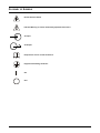
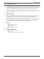
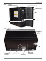
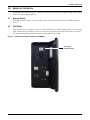
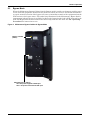
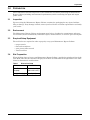
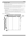
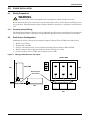
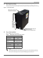
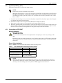
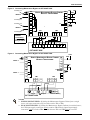
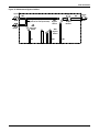
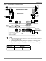
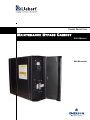
POWER PROTECTION
MAINTENANCE BYPASS CABINET
USER MANUAL
Wall-Mountable
TABLE OF CONTENTS
IMPORTANT SAFETY INSTRUCTIONS . . . . . . . . . . . . . . . . . . . . . . . . . . . . . . . . . . . . . . . . . . . . . . . .1
GLOSSARY OF SYMBOLS . . . . . . . . . . . . . . . . . . . . . . . . . . . . . . . . . . . . . . . . . . . . . . . . . . . . . . . .2
1.0
GENERAL DESCRIPTION . . . . . . . . . . . . . . . . . . . . . . . . . . . . . . . . . . . . . . . . . . . . . . . . . . .3
1.1
System Description. . . . . . . . . . . . . . . . . . . . . . . . . . . . . . . . . . . . . . . . . . . . . . . . . . . . . . . . . . . 3
1.2
Features . . . . . . . . . . . . . . . . . . . . . . . . . . . . . . . . . . . . . . . . . . . . . . . . . . . . . . . . . . . . . . . . . . . 3
1.3
Standard Components . . . . . . . . . . . . . . . . . . . . . . . . . . . . . . . . . . . . . . . . . . . . . . . . . . . . . . . . 3
2.0
MODES OF OPERATION . . . . . . . . . . . . . . . . . . . . . . . . . . . . . . . . . . . . . . . . . . . . . . . . . . . .5
2.1
Bypass Switch. . . . . . . . . . . . . . . . . . . . . . . . . . . . . . . . . . . . . . . . . . . . . . . . . . . . . . . . . . . . . . . 5
2.2
UPS Mode . . . . . . . . . . . . . . . . . . . . . . . . . . . . . . . . . . . . . . . . . . . . . . . . . . . . . . . . . . . . . . . . . . 5
2.3
Bypass Mode . . . . . . . . . . . . . . . . . . . . . . . . . . . . . . . . . . . . . . . . . . . . . . . . . . . . . . . . . . . . . . . . 6
3.0
PREPARATION . . . . . . . . . . . . . . . . . . . . . . . . . . . . . . . . . . . . . . . . . . . . . . . . . . . . . . . . . .7
3.1
Inspection . . . . . . . . . . . . . . . . . . . . . . . . . . . . . . . . . . . . . . . . . . . . . . . . . . . . . . . . . . . . . . . . . . 7
3.2
Environment . . . . . . . . . . . . . . . . . . . . . . . . . . . . . . . . . . . . . . . . . . . . . . . . . . . . . . . . . . . . . . . . 7
3.3
Required Setup Equipment . . . . . . . . . . . . . . . . . . . . . . . . . . . . . . . . . . . . . . . . . . . . . . . . . . . . 7
3.4
Site Preparation . . . . . . . . . . . . . . . . . . . . . . . . . . . . . . . . . . . . . . . . . . . . . . . . . . . . . . . . . . . . . 7
3.5
Mounting the Cabinet . . . . . . . . . . . . . . . . . . . . . . . . . . . . . . . . . . . . . . . . . . . . . . . . . . . . . . . . 8
4.0
CABLE INSTALLATION . . . . . . . . . . . . . . . . . . . . . . . . . . . . . . . . . . . . . . . . . . . . . . . . . . . . .9
4.1
Wiring Preparation. . . . . . . . . . . . . . . . . . . . . . . . . . . . . . . . . . . . . . . . . . . . . . . . . . . . . . . . . . . 9
4.1.1
4.2
Dual Source Configuration . . . . . . . . . . . . . . . . . . . . . . . . . . . . . . . . . . . . . . . . . . . . . . . . . . . . 9
4.2.1
4.3
Preparing Internal Wiring . . . . . . . . . . . . . . . . . . . . . . . . . . . . . . . . . . . . . . . . . . . . . . . . . . . . . . 9
Removing the Cover Plates . . . . . . . . . . . . . . . . . . . . . . . . . . . . . . . . . . . . . . . . . . . . . . . . . . . . 10
Power Cable Installation . . . . . . . . . . . . . . . . . . . . . . . . . . . . . . . . . . . . . . . . . . . . . . . . . . . . . 10
4.3.1
4.3.2
Input/Output Wiring (TB1) . . . . . . . . . . . . . . . . . . . . . . . . . . . . . . . . . . . . . . . . . . . . . . . . . . . . 11
Connection to GXT10000T . . . . . . . . . . . . . . . . . . . . . . . . . . . . . . . . . . . . . . . . . . . . . . . . . . . . . 11
5.0
OPERATING PROCEDURES . . . . . . . . . . . . . . . . . . . . . . . . . . . . . . . . . . . . . . . . . . . . . . . . 15
5.1
Start-Up and Initialization . . . . . . . . . . . . . . . . . . . . . . . . . . . . . . . . . . . . . . . . . . . . . . . . . . . 15
5.2
Shutting Down the UPS. . . . . . . . . . . . . . . . . . . . . . . . . . . . . . . . . . . . . . . . . . . . . . . . . . . . . . 15
5.3
Transferring System from UPS to Maintenance Bypass Operation . . . . . . . . . . . . . . . . . . . 15
5.4
Transfer of the System from Maintenance Bypass to UPS Operation . . . . . . . . . . . . . . . . . 15
6.0
MAINTENANCE . . . . . . . . . . . . . . . . . . . . . . . . . . . . . . . . . . . . . . . . . . . . . . . . . . . . . . . . . 16
6.1
Proper Care. . . . . . . . . . . . . . . . . . . . . . . . . . . . . . . . . . . . . . . . . . . . . . . . . . . . . . . . . . . . . . . . 16
7.0
SPECIFICATIONS . . . . . . . . . . . . . . . . . . . . . . . . . . . . . . . . . . . . . . . . . . . . . . . . . . . . . . . .17
i
FIGURES
Figure 1
Figure 2
Figure 3
Figure 4
Figure 5
Figure 6
Figure 7
Figure 8
Figure 9
Figure 10
Figure 11
Front view . . . . . . . . . . . . . . . . . . . . . . . . . . . . . . . . . . . . . . . . . . . . . . . . . . . . . . . . . . . . . . . . . . . . . . 4
Rear view . . . . . . . . . . . . . . . . . . . . . . . . . . . . . . . . . . . . . . . . . . . . . . . . . . . . . . . . . . . . . . . . . . . . . . . 4
Maintenance Bypass Cabinet in UPS Mode . . . . . . . . . . . . . . . . . . . . . . . . . . . . . . . . . . . . . . . . . . . 5
Maintenance Bypass Cabinet in Bypass Mode . . . . . . . . . . . . . . . . . . . . . . . . . . . . . . . . . . . . . . . . . 6
Wall-mount dimensions . . . . . . . . . . . . . . . . . . . . . . . . . . . . . . . . . . . . . . . . . . . . . . . . . . . . . . . . . . . 8
Wiring for dual sources. . . . . . . . . . . . . . . . . . . . . . . . . . . . . . . . . . . . . . . . . . . . . . . . . . . . . . . . . . . . 9
Cover plate removal . . . . . . . . . . . . . . . . . . . . . . . . . . . . . . . . . . . . . . . . . . . . . . . . . . . . . . . . . . . . . 10
Connecting Maintenance Bypass to GXT10000T-208X . . . . . . . . . . . . . . . . . . . . . . . . . . . . . . . . . 12
Connecting Maintenance Bypass to GXT10000T-240X . . . . . . . . . . . . . . . . . . . . . . . . . . . . . . . . . 12
Maintenance Bypass Cabinet . . . . . . . . . . . . . . . . . . . . . . . . . . . . . . . . . . . . . . . . . . . . . . . . . . . . . 13
Connecting Nfinity to Maintenance Bypass . . . . . . . . . . . . . . . . . . . . . . . . . . . . . . . . . . . . . . . . . . 14
TABLES
Table 1
Table 2
Table 3
Dimensional data . . . . . . . . . . . . . . . . . . . . . . . . . . . . . . . . . . . . . . . . . . . . . . . . . . . . . . . . . . . . . . . . 7
Nfinity power cable and protection ratings . . . . . . . . . . . . . . . . . . . . . . . . . . . . . . . . . . . . . . . . . . . 10
GXT 10kVA power cable and protection ratings . . . . . . . . . . . . . . . . . . . . . . . . . . . . . . . . . . . . . . . 11
ii
IMPORTANT SAFETY INSTRUCTIONS
SAVE THESE INSTRUCTIONS
This manual contains important instructions that should be closely followed during installation and
maintenance of this wall-mountable Maintenance Bypass Cabinet.
This product is designed for commercial/industrial use only. This product is not intended for use with
life support and other designated “critical” devices. Maximum load must not exceed that shown on the
UPS and the Maintenance Bypass Cabinet rating label.
!
WARNING
Lethal voltages may be present within this unit even when it is apparently not operating.
Observe all cautions and warnings in this manual. Failure to do so may result in serious
injury or death. Never work alone.
The Maintenance Bypass Cabinet is designed for use on properly grounded (earthed) 208/240 VAC, 50
or 60Hz supply, for installation by qualified personnel. This UPS equipment is intended to be
installed by a qualified / certified electrician who must review and approve customer supplied wiring,
circuit breakers, intended loads and verify correct input, output and grounded (earthed) connections
to ensure compliance with technical standards and national and local electrical codes. Installation
instructions and warning notices are located in 4.0 - Cable Installation.
!
CAUTION
To reduce the risk of fire:
The NMBHW4x model must be connected to a circuit provided with 100A maximum branch
circuit overcurrent protection in accordance with applicable national and local electrical
codes.
The NMBHW8x model must be connected to a circuit provided with 125A maximum branch
circuit overcurrent protection in accordance with applicable national and local electrical
codes.
Operate the UPS equipment in an indoor environment only in an ambient temperature range of 32°F
to 104°F (0°C to 40°C). Install it in a clean environment, free from conductive contaminants, moisture, flammable liquids, gases, or corrosive substances.
Never block or insert any object into the ventilation holes or other openings.
1
GLOSSARY OF SYMBOLS
Risk of Electrical Shock
Indicates Warning or Caution Followed by Important Instructions
AC Input
AC Output
i
Requests the user to consult the manual
Equipment Grounding Conductor
ON
OFF
2
General Description
1.0
GENERAL DESCRIPTION
Congratulations on your purchase of Liebert’s wall-mountable Maintenance Bypass Cabinet. As with
every Liebert product, we stand behind our quality. If you have any questions concerning this wallmountable Maintenance Bypass Cabinet, please feel free to contact your local dealer, Liebert representative, or call the appropriate Technical Support number listed on the back of this manual.
To ensure proper installation and operation of this unit, please read this manual thoroughly.
Installation must be done by a qualified/certified electrician, but general operation may be performed
without special training.
1.1
System Description
This wall-mountable Maintenance Bypass Cabinet is intended for use with the Nfinity, UPStation
GXT 6&10 kVA, or any other UPS with equivalent specifications. Typical applications include supporting workstations, servers, network, telecom or other sensitive electronic equipment.
The Maintenance Bypass Cabinet was designed to provide maximum system availability to business
critical equipment. The Maintenance Bypass Cabinet allows for transfer of connected loads to an
alternate power path allowing full isolation of the UPS. The UPS can then be turned “OFF” and
removed from service with no interruption of power to connected loads.
1.2
Features
•
•
•
•
1.3
Supports up to 20 kVA loads
High speed transfer switch
Compact design
Multiple power path indicators
Standard Components
• Easily accessible terminal blocks
• Wall-mountable
• Dual-source compatible for increased availability
3
General Description
Figure 1
Front view
Bypass Mode Indicator Lamp
UPS Mode Indicator Lamp
Lockout/Tagout Door
SW1
CB1
SW2
Figure 2
Rear view
End cover plate
(removable
for internal
inspection)
TB6
Slot for wall-mount
arrangement
(one of four)
End plate
(remove during
cable installation)
Knockout for cable
entrance (one of five)
Grounding lug
4
Modes of Operation
2.0
MODES OF OPERATION
The Maintenance Bypass Cabinet is designed to operate in UPS mode and Bypass mode. The mode is
selected using the Bypass Switch.
2.1
Bypass Switch
The Bypass Switch allows easy and rapid transfer of connected loads between the UPS and Bypass
source.
2.2
UPS Mode
While the Maintenance Bypass Cabinet is in the UPS Mode, the UPS is supplying the connected load
with continuous high quality AC power. In this mode of operation, the load is protected by the UPS.
The Bypass Switch rotated toward the green lamp indicates this mode.
Figure 3
Maintenance Bypass Cabinet in UPS Mode
UPS output
available (green)
5
Modes of Operation
2.3
Bypass Mode
When the Maintenance Bypass Cabinet is in the Bypass mode it provides an alternate path for power
to the connected equipment. Should the UPS need to be taken out of service for limited maintenance
or repair, manual activation of the bypass will cause an immediate transfer of the equipment from the
UPS inverter to the bypass source. The amber lamp illuminated in the Maintenance Bypass Switch
compartment indicates bypass is available. In this mode of operation the load is NOT protected by the
UPS. The Bypass Switch rotated toward the amber lamp indicates this mode. See 5.0 - Operating
Procedures for instructions on use.
Figure 4
Maintenance Bypass Cabinet in Bypass Mode
Bypass available
(amber)
UPS Input Source (amber)
ON = AC power supplied to UPS input
OFF = AC power removed from UPS input
6
Preparation
3.0
PREPARATION
These installation instructions provide all the information needed for positioning the Maintenance
Bypass Cabinet (including environmental requirements) and for connecting the input and output
power cables.
3.1
Inspection
Upon receiving the Maintenance Bypass Cabinet, examine the packaging for any signs of mishandling or damage. If any damage is noted, contact your local dealer or Liebert representative and notify
your carrier.
3.2
Environment
The Maintenance Bypass Cabinet environment must be free of conductive contaminants and excessive moisture (water condensation), flammable vapors, chemical fumes, or corrosive gases and liquids.
3.3
Required Setup Equipment
The tools below are required in order to properly set up your Maintenance Bypass Cabinet:
•
•
•
•
3.4
torque wrench
flat-head screwdriver
3/16" (5 mm) Allen wrench
T-20 Torx driver
Site Preparation
When deciding where to locate your Maintenance Bypass Cabinet, consider the weight and size of the
unit. Make sure that the structural integrity of the wall can withstand the weight. Refer to the table
below for dimensional considerations:
Table 1
Dimensional data
Model
WxDxH
In (mm)
Weight lbs, (kg)
NMBHWxx
20 x 8 x 18
(508 x 203 x 457)
45 (20.5)
7
Preparation
3.5
Mounting the Cabinet
This Maintenance Bypass Cabinet may be placed on the floor or mounted on a wall. In both cases,
ensure that the unit is in a well-ventilated area with at least 12 inches (305 mm) clearance for access
to the switches and cable connections.
When placing the cabinet on the floor, install the four rubber feet provided with the unit. One rubber
foot goes on each corner of the the unit on the side where keyhole slots have been cut.
If the Maintenance Bypass Cabinet is to be mounted on a wall, you must install hardware to support
the unit. Depending on the type of wall, you may need to install special anchors.
The Maintenance Bypass Cabinet has four keyhole-shaped slots to support it when mounted on a
wall. To mount the unit:
1. Mark the wall where you will install the mounting hardware, either screws, anchors or bolts
strong enough to support the unit (see Wall-mount dimensions on page 8 for layout
dimensions).
2. Insert the mounting screws, anchors or bolts, leaving enough clearance between the bolt heads
and the wall to accommodate the Maintenance Bypass Cabinet’s metal case.
3. Tighten the mounting bolts until they are snug, holding the Maintenance Bypass Cabinet firmly
against the wall.
Figure 5
Wall-mount dimensions
20"
(508mm)
1/2"
(12.7mm)
19"
(482.6mm)
18"
(457.2mm)
14"
(355.6mm)
2"
(50.8mm)
8
0.281"
1/4" (6.35mm)
hardware
Cable Installation
4.0
CABLE INSTALLATION
4.1
Wiring Preparation
!
WARNING
Please read this section thoroughly before attempting to install wiring to this unit.
Be sure that the unit is not connected to any AC mains power source or UPS before installing any wiring to this unit. This Maintenance Bypass Cabinet should be installed by a qualified / certified electrician.
4.1.1
Preparing Internal Wiring
The Maintenance Bypass Cabinet is factory-configured for single-source installations. If your installation requires dual-source capabilities, the Maintenance Bypass Cabinet’s wiring must be modified.
4.2
Dual Source Configuration
Modifying the wiring consists of removing the jumpers between TB1 and TB2 as described below:
1.
2.
3.
4.
5.
Figure 6
Remove cover plates.
Identify TB1 and TB2.
Using a 3/16" Allen wrench, loosen terminal mounting jumpers between TB1 and TB2.
Remove jumpers and retighten terminals to 22-26 in-lb (2.5 to 3.0 Nm).
Connect primary source to TB2 and secondary source to TB1.
Wiring modifications for dual inputs
FRONT VIEW
TB2
SIDE VIEW
TB2
Remove these
three cables
TB1
TB1
9
Cable Installation
4.2.1
Removing the Cover Plates
Plates cover the input and output terminals on the back of the Maintenance Bypass Cabinet (see
illustration below). Remove these using a T-20 Torx screwdriver. Keep screws and plates to one side.
Figure 7
Cover plate removal
Remove these screws to open
end plate and cover plate.
This
screw and
a second
screw
underneath
unit serve
as hinges
to open
end plate.
Remove these screws to open end
plate and cover plate
(fourth screw is underneath unit).
4.3
Power Cable Installation
Refer to Table 2 when selecting cables:
Table 2
Nfinity power cable and protection ratings
Model NMBHW4x
Max Input Current
100 A
Input Protection
100 A
Max Output Current
100 A
Input/ Output Terminal
Details
Max: 2/0 (70 mm2)
Min: 6 AWG (16 mm2)
Model NMBHW8x
Max Input Current
125 A
Input Protection
125 A
Max Output Current
125 A
Input/ Output Terminal
Details
Max: 2/0 (70 mm2)
Min: 6 AWG (16 mm2)
NOTE
Transient and steady state earth leakage currents may occur when starting the equipment.
This should be taken into account when selecting ground current detection devices, as these
will carry the earth leakage currents of both the UPS equipment and the load.
10
Cable Installation
4.3.1
Input/Output Wiring (TB1)
Follow the steps below to connect the input wiring:
NOTE
Input wiring must be installed using conduit.
208 input voltage jumper—if only the connections for 208 VAC are made between the UPS and
the Maintenance Bypass, the 208 input voltage jumper must be installed for proper operation.
To install this jumper, place the jumper wire provided in the accessory kit between Pin 1 and
Pin 2 on TB4.
1. Locate the input wiring access, remove the knockout and pull the three/four input wires through
it, allowing some slack for installation.
2. Secure the conduit to the rear panel of the Maintenance Bypass Cabinet.
3. Input power cables connect to hex terminals on the input terminal block.
4. Insert the ground (earth) wire through the earth lug and tighten it to the proper torque value (2226 in-lb). Then connect the wires to the block connections as shown below. Using a torque wrench,
turn the screws clockwise until tightened to the proper torque value (22-26 in-lb).
4.3.2
Connection to GXT10000T
Wiring Preparation
!
WARNING
Please read these instructions thoroughly before attempting to connect any wiring to this
unit.
Ensure that the unit is not connected to any AC utility power source or UPS before connecting
any wiring to this unit. Wiring connections should be performed only by a qualified/certified
electrician.
Power Cable Installation
Refer to Table 3 and subsequent illustrations when selecting cables.
Table 3
GXT 10kVA power cable and protection ratings
Max Input Current
208V
240V
45A
44A
Input Protection
60A
60A
Max Output Current
43A
42A
Terminal Block Details
Max: 35 mm2 (2/0 AWG)
Min: 16 mm2 (6 AWG)
NOTE
Transient and steady state earth leakage currents may occur when starting the equipment.
This should be taken into account when selecting ground current detection devices, as these
will carry the earth leakage currents of both the UPS equipment and the load.
11
Cable Installation
Figure 8
Connecting Maintenance Bypass to GXT10000T-208X
120V
Incoming L2
NFINITY MAINTENANCE BYPASS CABINET TB5
1
WITHOUT TRANSFORMER
TB2
L1
INPUT 2
Incoming L1
L2
2
N
3
INPUT 1
G
G
L2
Incoming L1
Caution
208V
4
G
TB1
L1
Incoming L2
120V
N
TB3
G
L1 L2
G
TB4
It is mandatory
to connect inputs
exactly as shown.
G
1
2
3
4
GEC
L1
L2
N
Input
L1
L2 L2A
Output
External Battery
GXT10000T-208X
Figure 9
Connecting Maintenance Bypass to GXT10000T-240X
TB2
INPUT 2
INPUT 1
L1
NFINITY MAINTENANCE BYPASS CABINET TB5
1
WITHOUT TRANSFORMER
L2
2
N
3
120V
240V
4
G
TB1
L1
G
G
L2
N
TB3
G
L1 L2
G
TB4
G
1
2
3
4
GEC
L1
L2
Input
N
L1
Output
L2
External Battery
GXT10000T-240X
NOTES
1. SINGLE-SOURCE FEED—If feeding the Maintenance Bypass Cabinet from a single
source, the input connection may be made to either TB1 or TB2.
2. DUAL-SOURCE FEED—If feeding the Maintenance Bypass Cabinet from a dual source,
the UPS input supply connection must be made to TB1 and the bypass input supply
connection must be made to TB2. The link between TB1 and TB2 must be removed.
12
Cable Installation
Figure 10 Maintenance Bypass Cabinet
Input 2
TB5
TB2
Single input jumper
(remove for dual input feeds)
TB1
Input 1
SW2
UPS Input
Switch
CB1
Output
Breaker
SW1
Bypass
Switch
TB3
UPS Input
SW1
Bypass
Switch
TB6
N/C
C
N/0
13
TB4
UPS Output
Output
Cable Installation
Figure 11 Connecting Nfinity to Maintenance Bypass
TB2
TB5
L1
Input 2
120
120
208
240
1
2
3
MAINTENANCE BYPASS CABINET
L2
N
4
Remove these three
wires for dual source
G
TB1
Input 1
G
L1
G
L2
N
G
TB6
G
TB3
L1 L2
G
1
TB4
2 3 4
NO
Common
NC
Flexible
conduit
L1 L2
G
1 2 3
TB1
TB2
Ensure that the tap
selector is set to the
correct input voltage
1
2 3 4 5
TB3
GEC
See the user
manual for your
UPS for details
on connecting GEC.
UPS
NOTE
1. If feeding the Maintenance Bypass Cabinet from a single source, the input connection may
be made to either TB1 or TB2.
2. If feeding the Maintenance Bypass Cabinet from a dual source, the UPS input supply
connection must be made to TB1 and the bypass input supply connection must be made to
TB2. The link between TB1 and TB2 must be removed.
3. TB6 provides Normally Open and Normally Closed contacts to indicate operation of the
bypass switch.
Maintenance Bypass
Switch Position
TB6 Contacts
Bypass
NO - Common: Open
NC - Common: Closed
UPS
NO - Common: Closed
NC - Common: Open
14
Operating Procedures
5.0
OPERATING PROCEDURES
5.1
Start-Up and Initialization
Follow these steps to start up the UPS while connected to the Maintenance Bypass.
1.
2.
3.
4.
5.
6.
5.2
Set Maintenance Bypass switch (SW1) to UPS position on Maintenance Bypass Cabinet.
Close UPS source switch (SW2).
Close output circuit breaker (CB1).
Close input circuit breaker (CB1).
On UPS, close control enable switch (SW2).
After UPS has initialized, turn UPS output on by pushing the standby button.
Shutting Down the UPS
Use the following procedure to power down the system.
1.
2.
3.
4.
5.
5.3
Turn UPS output off by pushing the Standby button.
Open the control enable switch (SW2) on the UPS.
Open the input circuit breaker (CB1) on the UPS.
Open the UPS source switch (SW1) on the Maintenance Bypass Cabinet.
Open the output circuit breaker (CB1) on the Maintenance Bypass Cabinet.
Transferring System from UPS to Maintenance Bypass Operation
1. Verify that the amber bypass lamp is illuminated
2. Turn the bypass switch (SW1) to the bypass position on the Maintenance Bypass Cabinet. The
connected equipment is now powered from the bypass source and is not protected.
5.4
Transfer of the System from Maintenance Bypass to UPS Operation
1.
2.
3.
4.
Close the UPS source switch (SW1) on the Maintenance Bypass Cabinet.
Close the input circuit breaker (CB1) on the UPS.
Close the control enable switch (SW2) on the UPS.
Turn the UPS output on by pushing the standby button on the UPS. Verify the Green UPS lamp
is illuminated.
5. Turn the bypass switch to the bypass position on the Maintenance Bypass Cabinet.
15
Maintenance
6.0
MAINTENANCE
6.1
Proper Care
Keeping your Liebert Maintenance Bypass Cabinet operating properly is imperative to optimal performance and life of the unit. It is recommended that a certified technician perform preventive and
corrective maintenance.
Liebert Global Services (LGS) is dedicated to ensuring the highest level of performance and
unmatched support for your Maintenance Bypass Cabinet. Contact an LGS representative for services to guarantee maximum reliability and system availability.
16
Specifications
7.0
SPECIFICATIONS
General & Environmental
NMBHW4x = 16kVA
NMBHW8x = 20kVA
Unit Rating
NMBHW4x = 100A max
NMBHW8x = 125A max
Compliant Safety Standards
UL 1778, c-UL
Mechanical
Dimensions, WxDxH, in. (mm)
20 x 8 x 18 (508 x 203 x 457)
Weight
45 lb. (20.5 kg)
Environmental
Operating Temperature, maximum
32° - 104°F (0° - 40°C)
Relative Humidity
5 - 95% noncondensing
Operating Altitude, maximum
10,000 ft.; (3,000m)
Input Data
Nominal Input Voltage
208 or 240VAC
Input Frequency, nominal
50 or 60Hz
Input Frequency Range
Output Data
Output Voltage, VAC
45-55Hz or 55-65Hz
208/240
240
208
120/120/208/240
120/120/240
120/120/208
Transfer Time
<4 msec typical
Output Frequency
50 or 60Hz (same as input)
Maximum Voltage
120VAC
Maximum Current
5A
TB6 Contacts
17
Specifications
18
POWER PROTECTION
Maintenance Bypass Cabinet
USER MANUAL
The Company Behind the Products
With over a million installations around the globe,
Liebert is the world leader in computer protection
systems. Since its founding in 1965, Liebert has
developed a complete range of support and
protection systems for sensitive electronics:
•
•
•
•
•
Environmental systems—close-control air
conditioning from 1 to 60 tons
Power conditioning and UPS with power
ranges from 300 VA to more than 1000 kVA
Integrated systems that provide both
environmental and power protection in a
single, flexible package
Monitoring and control—from systems of any
size or location, on-site or remote
Service and support through more than 100
service centers around the world and a 24/7
Customer Response Center
While every precaution has been taken to ensure
the accuracy and completeness of this literature,
Liebert Corporation assumes no responsibility and
disclaims all liability for damages resulting from
use of this information or for any errors or
omissions.
© 2003 Liebert Corporation
All rights reserved throughout the world.
Specifications subject to change without notice.
® Liebert and the Liebert logo are registered
trademarks of Liebert Corporation. All names
referred to are trademarks or registered
trademarks of their respective owners.
SL-23967 (11/03) Rev. 1
Technical Support/Service
Web Site
www.liebert.com
Monitoring
800-222-5877
[email protected]
Outside the US: 614-841-6755
Single-Phase UPS
800-222-5877
[email protected]
Outside the US: 614-841-6755
Three-Phase UPS
800-543-2378
[email protected]
Environmental Systems
800-543-2778
Outside the United States
614-888-0246
Locations
United States
1050 Dearborn Drive
P.O. Box 29186
Columbus, OH 43229
Italy
Via Leonardo Da Vinci 8
Zona Industriale Tognana
35028 Piove Di Sacco (PD)
+39 049 9719 111
Fax: +39 049 5841 257
Asia
23F, Allied Kajima Bldg.
138 Gloucester Road
Wanchai
Hong Kong
+852 2 572 2201
Fax: +852 2 831 0114