1
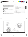
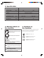
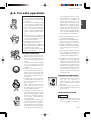
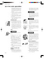
HB2302 / HBZ2601
848L0B93A2 (704)
G
B
OWNER’S MANUAL
BLOWERS
HB2302
HBZ2601
GB-1
HB2302 / HBZ2601
ZENOAH CO., LTD
EXPLANATION OF SYMBOLS AND SAFETY WARNINGS
WARNING!!!
RISK OF DAMAGING HEARING
Wear head, eye and ear protection.
MODEL
HB2302
HBZ2601
22.5cm3
25.4cm3
SOUND LEVEL
ISO 11094
LwA
guaranteed
measured
104dB(A)
106dB(A)
104dB(A)
106dB(A)
VIBRATION LEVEL
ON HANDLE
ISO 7916
idling
racing
4.7m/s2
11.1m/s2
4.7m/s2
11.1m/s2
APPROVAL NUMBER OF CE EXHAUST EMISSION REGULATION (2002/88/EC)
HB2302 : e13*97/68SH2G3*2002/88*0104*02
HBZ2601 : e13*97/68SH2G3*2002/88*0094*03
GB-2
HB2302 / HBZ2601
SAFETY FIRST
Instructions contained in warnings within this manual marked
with a
symbol concern critical points which must be taken
into consideration to prevent possible serious bodily injury, and
for this reason you are requested to read all such instructions
carefully and follow them without fail.
WARNINGS IN THE MANUAL
WARNING
This mark indicates instructions, which must be followed in order to prevent accidents, which could lead to serious bodily injury or death.
IMPORTANT
This mark indicates instructions, which must be followed, or it
leads to mechanical failure, breakdown, or damage.
NOTE
This mark indicates hints or directions useful in the use of the
product.
Contents
1.
2.
3.
4.
5.
6.
7.
8.
9.
10.
11.
12.
13.
Parts location .................................................. 3
Specifications ................................................. 4
Warning labels on the machine ...................... 4
Symbols on the machine ................................ 4
For safe operation ........................................... 5
Set up ............................................................. 8
Fuel ................................................................. 9
Operation ...................................................... 10
Maintenance ................................................. 11
Storage ......................................................... 13
Disposal ........................................................ 13
Optional vacuum kit usage ........................... 14
Troubleshooting guide .................................. 16
1. Parts location
1.
2.
3.
4.
5.
6.
7.
8.
9.
Stop Switch
Throttle Lever
Air Intake Screen (Air inlet net)
Spark Plug Cap
Recoil Starter Knob
Air Cleaner
Fuel Tank
Blower Pipe
Screw
GB-3
G
B
HB2302 / HBZ2601
2. Specification
Model
HB2302
HBZ2601
Dimensions (LxWxH)
mm
325 x 230 x 360
327 x 268 x 360
Dry weight (w/o tube and nozzle) kg
3.7
3.9
Fuel tank capacity
liter
0.75
0.65
Engine Type
Air cooled 2-cycle gasoline engine
Displacement
cm3
22.5
25.4
Carburetor
Diaphragm type (Walbro)
Ignition system
T.C.I.
C.D.I.
Spark plug
Champion RCJ6Y (noise proof)
NGK CMR7A
Muffler
Spark arrester equipped
Operating Engine Speed
rpm
2300 to 7500
2800 to 7890
Idle speed
rpm
2300
2800
Average Air Volume
cu.m/min.
10
10
Max. Air Velocity
m/sec.
67
70
Noise Level at 50 feet
dB
70
69
Specifications are subject to change without notice.
3. Warning labels on
the machine
Read owner’s manual before operating this machine.
4. Symbols on
the machine
For safe operation and maintenance, symbols are carved
in relief on the machine. According to these indications,
please be careful not to make a mistake.
The port to refuel the “MIX GASOLINE”
Position: FUEL TANK CAP
Wear head, eye and ear protection.
The direction to close the choke
Position: ENGINE COVER
Warning / Attention
Keep all children, bystanders and helpers 15
meters away from the machine.
If warning label peels off or becomes soiled and
impossible to read, you should contact the
dealer from which you purchased the product
to order new labels and affix them in the required
location(s).
Never modify your machine.
We won’t warrant the machine, if you use the
remodeled blower or if you don’t observe the
proper usage written in the manual.
GB-4
The direction to open the choke
Position: ENGINE COVER
HB2302 / HBZ2601
5. For safe operation
1. Read this manual carefully until
you completely understand and
follow all safety and operating
instructions.
2. Keep this manual handy so that
you may refer to it later whenever any questions arise. Also
note, if you have any questions
which cannot be answered
herein, contact the dealer from
whom you purchased the product.
3. Always be sure to include this
manual when selling, lending, or
otherwise transferring the ownership of this product.
4. Do not lend or rent your machine
without the owner's manul.
5. Be sure that anyone using your
unit understands the infomation
contained in this manual.
6. Never let a child under 13 years
old use the machine.
WORKING CONDITION
1. Refrain from operating the
blower if you are tired, ill, or upset, or if you are under the influence of alcohol, drugs or medication.
2. To reduce the risk of hearing
loss associated with sound
level(s), hearing protection is
required.
3. To reduce the risk of injury associated with thrown objects,
always wear eye protection and
foot protection. Eye protection
should meet the requirements of
ANSI Z87.1.
4. To reduce the risk of injury associated with the inhalation of
dust, use a face filter mask in
dusty conditions.
5. Wear rubber-soled shoes or
shoes with some other form of
anti-slip protection to help protect you against falling.
6. To reduce the risk of injury associated with objects being
drawn into rotating parts, do not
wear loose clothing, scarves,
neck chains, unconfined long
hair, and the like.
7. Prolonged use of a blower, exposing the operator to vibrations
and cold may produce
whitefinger disease (Raynaud’s
phenomenon), which symptoms
are tingling and burning sensa-
tions followed by loss of color
and numbness in the fingers. All
factors which contribute to
whitefinger disease are not
known, but cold weather, smoking diseases or physical conditions as well as long periods of
exposure to vibration are mentioned as factors. In order to reduce the risk of whitefinger disease, the following precautions
are strongly recommended;
a) Keep your body warm. Never
use blower during rains.
b) Wear thick anti-vibration gloves.
c) Take more than 5 minutes of
break in warm place frequently.
d) Maintain a firm grip at all times,
but do not squeeze the handles
with constant, excessive pressures.
e) If you feel discomfort, redness
and swelling of your fingers or
any other part of your body, see
a doctor before getting worse.
8. The ignition system of your unit
produces an electromagnetic
field of a very low intensity. This
field may interfere with some
pacemakers. To reduce the risk
of serious or fatal injury, persons
with pacemaker should consult
their physician and the pacemaker manufacturer before operating this tool.
WORKING CIRCUMSTANCE
1. To reduce the risk of injury associated with exhaust fume inhalation, do not operate in
unventilated area. The exhaust
gases contain harmful carbon
monoxide.
2. Avoid using the blower where
stable footing and balance are
not assured.
AVOID NOISE PROBLEM
NOTE
• Check and follow the local regulations as to sound level and
hours of operations for blower.
GB-5
G
B
HB2302 / HBZ2601
5. For safe operation
1. Operate power equipment only at
reasonable hours-not early in the
morning or late at night when
people might be disturbed. Comply with times listed in local ordinances.
2. To reduce sound levels, limit the
number of pieces of equipment
used at any one time.
3. Operate power blowers at the
lowest possible throttle speed to
do the job.
4. Check your equipment before operation, especially the muffler, air
intakes and air filters.
any damage is found in the fuel
line, the exhaust line, or the ignition wiring, do not use the blower
until it has been repaired.
IMPORTANT
• Before starting operation, always
make sure to check if any obstacles are left inside the volute
case. The obstacles may cause
damage on fan and volute case
and serious injury.
WARNING
WORKING PLAN
• When planning your work schedule, allow plenty of time to rest.
Limit the amount of time over
which the product is to be used
continuously to somewhere
around 30 ~ 40 minutes per session, and take 10 ~ 20 minutes of
rest between work sessions. Also
try to keep the total amount of
work performed in a single day
under 2 hours or less.
• Never use the blower without the
screen at the air intake of the
blower. Before each use, check
that, the screw (1) is securely
tightened and is free from any
damage.
FUEL
(1) Screw
(2) Air intake screen (Air inlet net)
• Never remove debris from the intake screen while the engine is
running. Contact with rotating
blower fan may result in a serious
personal injury.
WARNING
WARNING
To reduce the risk of fire and burn
injury:
GB-6
• To reduce the risk of injury associated with contacting rotating
parts, stop the engine before installing or removing attachments.
Do not operate without net in
place. Always disconnect the
spark plug before performing
maintenance or accessing movable parts.
a) Handle fuel with care. It is highly
flammable.
b) Do not smoke while handing fuel.
c) Do not refuel a hot engine.
d) Do not refuel a running engine.
e) Avoid spilling fuel or oil. Always
wipe unit dry before using.
f) Move at least 10 ft. (3 meters)
away from the fueling point before starting engine.
g) Always store gasoline in a container approved for flammable liquids.
h) Make sure the unit is properly assembled and in good operating
condition.
USING THE PRODUCT
1. Check the work area that the
blower will be used in and remove
or cover all valuables that may be
damaged by the air blast or
thrown debris.
2. To reduce the risk of injury associated with thrown objects.
BEFORE STARTING THE
ENGINE
• Each time before starting the engine, inspect the entire unit to see
if every part is in good order and
is securely tightened in place. If
a) Watch out for children, pets, open
windows or freshly washed cars,
and blow debris safely away.
b) Use the full blower nozzle extension so the air stream can work
close to the ground.
HB2302 / HBZ2601
5. For safe operation
c) Do not allow bystanders in work
area.
d) Do not point the blower nozzle in
the direction of people or pets.
e) Always check to be sure that no
debris has been blown onto
someone else’s property.
f) Pay attention to the direction of
the wind, do not work against the
wind.
3. To minimize blowing time.
a) Use rakes and brooms to loosen
debris before blowing.
b) In dusty conditions, slightly
dampen surfaces or use mister
attachment when water is available.
c) Conserve water by using power
blowers instead of hoses for many
lawn and garden applications,
including areas such as gutters,
screens, patios, grills, porches
and gardens.
4. Never to touch the spark plug or
plug cord while the engine is in
operation. Doing so may result in
being subjected to an electrical
shock.
5. Never to touch the muffler, spark
plug, or other metallic parts of the
engine while the engine is in operation or immediately after shutting down the engine. These metallic parts reach high temperatures during operation and doing
so could result in serious burns.
6. After using blowers and other
equipment, CLEAN UP! Dispose
of debris in trash receptacles.
MAINTENANCE
1. In order to maintain your product
in proper working order, perform
the maintenance and checking
operations described in the
manual at regular intervals.
2. Always be sure to turn off the engine and disconnect the spark
plug before performing any maintenance or checking procedures.
3. Examine the blower at intervals
for loose fasteners and rusted or
damaged parts. Use special care
around the fuel line, the muffler,
and the ignition wiring.
4. All engine service except for
those described in this manual
should be performed by competent service personnel. Improper
service to the blower fan and muffler could cause a hazardous failure.
5. When replacing the any other
part, or any lubricant, always be
sure to use only Zenoah products
or products which have been certified by Zenoah for use with the
Zenoah product.
6. In the event that any part must be
replaced or any maintenance or
repair work not described in this
manual must be performed,
please contact a representative
from the store nearest Zenoah authorized servicing dealer for assistance.
7. Do not use any accessory or attachment other than those bearing the Zenoah mark and recommended for the unit.
8. Under no circumstances should
you ever take apart the product
or alter it in any way. Doing so
might result in the product becoming damaged during operation or the product becoming unable to operate properly.
TRANSPORTATION
• Drain the fuel from the fuel tank
before transporting or storing the
blower.
STORAGE
• When storing the blower, choose
a space indoors free from moisture and out of the reach of children.
WARNING
• The metallic parts reach high temperatures immediately after stopping the engine.
GB-7
G
B
HB2302 / HBZ2601
6. Set up
BLOWER PIPE
• Align groove in blower pipe with projection on blower
housing (or another blower pipe) and slide the pipe
onto the blower housing (or another blower pipe).
Rotate the pipe clockwise to lock it into place.
GB-8
HB2302 / HBZ2601
7. Fuel
■ FUEL
• Gasoline is very flammable. Avoid smoking or
bringing any flame or sparks near fuel. Make sure
to stop the engine and allow it cool before refueling the unit. Select outdoor bare ground for fueling and move at least 3 m (10 ft) away from the
fueling point before starting the engine.
• The Zenoah engines are lubricated by oil specially
formulated for air-cooled 2-cycle gasoline engine use.
If Zenoah oil is not available, use an anti-oxidant added
quality oil expressly labeled for air-cooled 2-cycle engine use (JASO FC GRADE OIL or ISO EGC GRADE).
• Do not use BIA or TCW (2-stroke water-cooling type)
mixed oil.
■ RECOMMENDED MIXING RATIO
GASOLINE 50 : OIL 1
(when using ZENOAH genuine oil)
• Exhaust emission are controlled by the fundamental engine parameters and components (eq.,
carburation, ignition timing and port timing) without addition of any major hardware or the introduction of an inert material during combustion.
• These engines are certified to operate on unleaded
gasoline.
• Make sure to use gasoline with a minimum octane
number of 89RON (USA/Canada: 87AL).
• If you use a gasoline of a lower octane value than prescribed, there is a danger that the engine temperature may rise and an engine problem such as piston
seizing may consequently occur.
• Unleaded gasoline is recommended to reduce the
contamination of the air for the sake of your health
and the environment.
• Poor quality gasolines or oils may damage sealing
rings, fuel lines or fuel tank of the engine.
■ HOW TO MIX FUEL
3. Pour in all of the oil and agitate well.
4. Pour in the rest of gasoline and agitate again for at
least one minute. As some oils may be difficult to agitate depending on oil ingredients, sufficient agitation
is necessary for the engine to last long. Be careful
that, if the agitation is insufficient, there is an increased
danger of early piston seizing due to abnormally lean
mixture.
5. Put a clear indication on the outside of the container
to avoid mixing up with gasoline or other containers.
6. Indicate the contents on outside of container for easy
identification.
■ FUELING THE UNIT
1. Untwist and remove the fuel cap. Rest the cap on a
dustless place.
2. Put fuel into the fuel tank to 80% of the full capacity.
3. Fasten the fuel cap securely and wipe up any fuel spillage around the unit.
1. Select bare ground for fueling.
2. Move at least 10 feet (3 meters) away from the fueling
point before starting the engine.
3. Stop the engine before refueling the unit. At that time,
be sure to sufficiently agitate the mixed gasoline in
the container.
■ FOR YOUR ENGINE LIFE, AVOID:
1. FUEL WITH NO OIL (RAW GASOLINE) – It will cause
severe damage to the internal engine parts very
quickly.
2. GASOHOL – It can cause deterioration of rubber and/
or plastic parts and disruption of engine lubrication.
3. OIL FOR 4-CYCLE ENGINE USE – It can cause spark
plug fouling, exhaust port blocking, or piston ring sticking.
4. Mixed fuels which have been left unused for a period of one month or more may clog the carburetor
and result in the engine failing to operate properly.
5. In the case of storing the product for a long period of
time, clean the fuel tank after rendering it empty. Next,
activate the engine and empty the carburetor of the
composite fuel.
6. In the case of scrapping the used mixed oil container,
scrap it only at an authorized repository site.
• As for details of quality assurance, read the description in the section Limited Warranty carefully. Moreover, normal wear and change in product with no functional influence are not covered by the warranty. Also,
be careful that, if the usage in the instruction manual
is not observed as to the mixed gasoline, etc. described therein, it may not be covered by the warranty.
• Pay attention to agitation.
1. Measure out the quantities of gasoline and oil to be
mixed.
2. Put some of the gasoline into a clean, approved fuel
container.
GB-9
G
B
HB2302 / HBZ2601
8. Operation
STARTING ENGINE
1. Rest the unit on a flat, firm place.
2. Pump the primer until fuel flows out in the clear tube.
(1) Primer
RESTARTING ENGINE WHILE ENGINE IS HOT
1. When restarting the engine immediately after stopping it, leave the choke open.
2. If the engine won’t start after several attempts, close
the choke and repeat pulling the rope or remove the
spark plug and dry it.
ADJUSTING IDLE SPEED
1. When the engine tends to stop frequently at an idle
mode, turn the adjusting screw clockwise.
(1) Idling adjustment screw
(2) Cable Adjuster
3. Move the choke lever upward to close the choke.
NOTE
(1) Choke lever
(2) Close
(3) Open
4. Holding the blower handle, pull the starter rope with
your right hand.
(Throttle lever in idle or start position.)
• Warm up the engine before adjusting the idle speed.
STOPPING ENGINE
• Move the throttle lever to the idling position and press
the stop swich (red button) until the engine comes to
a complete stop.
(1) Stop switch
NOTE
IMPORTANT
• Avoid pulling the starter rope out to its full extent and
allowing the starter rope to snap back. This will prevent premature damage to the starter.
• Do not let a person stand near the blower or the exhaust port.
5. When the engine has started, move the choke lever
gradually downward to open the choke.
6. Allow the engine to warm up for a half minute before
starting operation.
GB-10
• Except for an emergency, avoid stopping the engine
while pulling the throttle lever.
HB2302 / HBZ2601
9. Maintenance
Maintenance, replacement, or repair of the emission control device and systems may be performed by any non-road engine repair establishment or individual.
System / Compronent
Procedure
Air Filter
Prefilter
Air Filter
Paper Filter
Fuel Leaks
Fuel Filter
Fuel Line
Spark Plug
Muffler
Muffler Spark Arrester
Cooling Systrem
Screws / Nuts / Bolts
Cylinder Exhaust Port
Inspect / Clean
Inspect / Replace
Inspect / Replace
Inspect / Replace
Inspect / Clean
Inspect / Clean
Inspect / Clean
Inspect / Clean
Inspect / Clean
Tighten
Inspect / Clean
WARNING
Daily
or
Before use
✔
✔
✔
✔
✔
Every
25 hours
after
Every
Every
50 hours 100 hours
after
after
✔
✔
✔
✔
✔
✔
✔
[HBZ2601]
1. Remove the air cleaner cover.
Make sure that the engine has stopped and is
cool before performing any service to the
blower. Contact with rotating blower fan or hot
muffler may result in a personal injury.
AIR CLEANER
• Never operate the blower without an air filter or with a
deformed or broken filter element.
• Check the air cleaner before use.
A clogged air filter may increase fuel consumption
while cutting down the engine power. Never operate
the blower without the air filter or with a deformed filter element because unfiltered dusty air will quickly
ruin the engine.
CLEANING AIR FILTER:
[HB2302]
1. Remove the air cleaner cover by pushing and pulling
back the tab on the top.
2. Use neutral detergent and warm water to clean the
filter element. After cleaning, air dry the element completely.
3. Install the filter element into the air cleaner housing
and press the cover against the housing until clicks.
If the element is broken or shrunk, replace with a new
one.
2. Use neutral detergent and warm water to clean the
filter element. After cleaning, air dry the element completely.
3. Reinstall the filter. Never forget to attach the screen. If
the screen is not attached, the cleaner will not seal
properly and the dusts come into the cylinder.
(1) Element
(2) Screen
GB-11
G
B
HB2302 / HBZ2601
9. Maintenance
FUEL FILTER
• A clogged fuel filter may cause poor acceleration of
the engine. Check periodically to see if the filter is
clogged with dirt. The filter can be taken out of the
fueling port using a small wire hook. Disconnect the
filter assembly from the fuel pipe and unhook the retainer to disassemble it. Clean the components with
gasoline.
MUFFLER
WARNING
• Inspect periodically, the muffler for loose fasteners,
any damage or corrosion. If any sign of exhaust leakage is found, do not use the blower and have it repaired immediately.
• Note that failing to do so may result in the engine
catching on fire.
IMPORTANT
SPARK PLUG
• The spark plug may gather carbon deposits on its
firing end with reasonable use. Remove and inspect
the spark plug every 25 hours and clean the electrodes as necessary with a wire brush. The spark gap
should be adjusted to .025 in (0.6~0.7mm).
• Plug manufacturers recommend replacing the plug
twice a year to avoid unexpected plug failure in a job.
REPLACEMENT PLUG
HB2302 : CHAMPION RCJ6Y
HBZ2601 : NGK CMR7A
IMPORTANT
• Note that using any spark plugs other than those designated may result in the engine failing to operate
properly or in the engine becoming overheated and
damaged.
• To install the spark plug, first turn the plug until it is
finger tight, then tighten it a quarter turn more with a
socket wrench.
GB-12
• Before starting operation, always make sure to check
if the muffler is properly held by three bolts to the cylinder. (Fastening Torque : 8~12 N·m)
• Even if one bolt out of three bolts is loose, the muffler
may get loose during operation which may result in
engine catching on fire.
PROCEDURES TO BE PERFORMED AFTER EVERY 100 HOURS OF USE
1. Remove the muffler, insert a screwdriver into the vent,
and wipe away any carbon buildup. Wipe away any
carbon buildup on the muffler exhaust vent and cylinder exhaust port at the same time.
2. Tighten all screws, bolts, and fittings.
SPARK ARRESTER
• The engine is equipped with a spark arresting screen
at the exhaust port. Periodically check and keep it in
good condition. In the state of California it is required
by law (Section 4442 of the California Public Resources Code) to equip a spark arrester when a gas
powered tool is used in any forest covered, brush
covered, or grass covered unimproved land.
HB2302 / HBZ2601
9. Maintenance
10. Storage
AIR INTAKE SCREEN (AIR INLET NET)
BEFORE STORING THE BLOWER:
1. Drain a fuel tank and push the primer bulb until it becomes empty of fuel.
2. Remove the spark plug and drop a spoonful of 2-cycle
oil into the cylider. Crank the engine several times and
install the spark plug.
3. Store unit in a dry, dust free place, out of the reach of
children.
IMPORTANT
• Blowing air is taken in from the air inlet net. When air
flow has dropped down during operation, stop the
engine and inspect the air inlet net for blocking by
obstacles.
• Note that failure to remove any such obstacles may
result in the engine becoming overheated and damaged.
(1)Screw
(2)Air intake screen
(Air inlet net)
WARNING
• Never use the blower without the net of the blower.
Before each use, check that the net is attached in
place and is free from any damage.
11. Disposal
When disposing your machine, fuel or oil for the machine,
be sure to allow your local regulations.
GB-13
G
B
HB2302 / HBZ2601
12. Optional vacuum kit usage
Attach the adequate accessories, respectively
for blower operation and dust-collecting operation.
2. Align the
with the
(5) indicated on the vacuum pipe (4)
indicated on the blower. Then insert the
vacuum pipe (4) into the blower.
NOTE
• Use the gloves during operation.
• In adjustment of the blower/dust collector or in other
types of operation, be sure to stop the engine and
detach the spark plug cap.
• Never start operation unless this machine is completely assembled.
MOUNTING THE DUST-COLLECTING KIT
1) Installing Support Handle
• This handle is supplied with the blower.
• Fit the holes of volute and handle, tighten the screws.
• Be sure to tighten the screws straightly.
3. Turn the vacuum pipe (4) until the
with the
(5) is aligned
indicated on the blower to lock the vacuum
pipe.
(1) Support Handle
(2) Holes
(3) Screws
WARNING
• Hold the bottom of the vacuum pipe when turning the
vacuum pipe to install or remove it.
2)
1. Fit the extension pipe (1) groove with main unit port
projection, turn to mount the pipe to the main unit.
2. Tighten the clamp screw (2) securely.
4) Installing Elbow and Dust Bag
1. Open the fastener of the dust bag.
(6)Convex Groove
(7)Convex End
3) Installing Vacuum Pipe (nozzle)
1. Loosen the screw (3), and open the suction port cover.
2. Insert the elbow convex groove into the dust bag elbow opening.
Continue to push the elbow convex groove until the
convex hits against the dust bag opening.
Close the dust bag fastener.
(8)Groove
GB-14
HB2302 / HBZ2601
12. Optional vacuum kit usage
3. Fit the elbow groove with discharge port projection,
turn the elbow and mount the dust bag to the main
unit.
DUST COLLECTING OPERATION
• Put the dust bag belt on the shoulder, and adjust the
length of the belt so as to permit easy operation.
• Confirm that the dust bag is not twisted, pull the throttle
trigger, and start dust collecting operation.
• Detach the dust bag from the main unit when it is full
of dust, open the dust bag fastener, and dispose of
dust.
G
B
WARNING
• Never suck in any liquid or lit cigarette.
It will lead to an electric shock or burn.
NOTE
• Never suck in large wood chips, metal, glass, small
stones or other foreign materials.
• A filled dust bag will lessen dust-collecting capacity.
It is advisable to discharge dust before it becomes
too much.
(A)
(B)
(C)
(D)
(E)
Indicates Warning, Danger, and Caution.
Keep work area clear of other per-sons and pets.
Risk of long hair being drawn into air inlet.
Wear head, eye, and hearing protection when op
erating this equipment.
Do not run unit while vacuum door is unsecured.
GB-15
HB2302 / HBZ2601
13. Troubleshooting guide
Case 1. Starting failure
CHECK
fuel tank
fuel filter
carburetor adjustment screw
sparking (no spark)
spark plug
→
→
→
→
→
→
PROBABLE CAUSES
incorrect fuel
fuel filter is clogged
out of normal range
spark plug is fouled/wet
plug gap is incorrect
disconnected
Case 2. Engine starts but does not keep running/hard re-starting
CHECK
PROBABLE CAUSES
fuel tank
→ incorrect fuel or staled fuel
carburetor adjustment screw → out of normal range
muffler, cylinder (exhaust port) → carbon is built-up
air cleaner
→ clogged with dust
cylinder fin, fan cover
→ clogged with dust
→
→
→
→
→
→
ACTION
drain it and use correct fuel
clean
adjust to normal range
clean/dry
correct (GAP: 0.6 ~ 0.7 mm)
retighten
→
→
→
→
→
ACTION
drain it and use correct fuel
adjust to normal range
wipe away
wash
clean
When your unit seems to need further service, please consult with our ZENOAH service shop in your area.
Limited warranty
Should any failure occur on the product under normal operating conditions within the applicable warranty period, the
failed part will be replaced or repaired free of charge by a
ZENOAH authorized dealer.
WARRANTY PERIOD: 1 year (6 months if used professionally, and 30 days if used for rental purpose) from the date of
initial purchase.
THE PURCHASER SHALL BEAR COSTS OF TRANSPORTING THE UNIT TO AND FROM THE ZENOAH DEALER.
THE PURCHASER SHALL NOT BE CHARGED FOR DIAGNOSTIC LABOR WHICH LEADS TO THE DETERMINATION
THAT A WARRANTED PART IS DEFECTIVE, IF THE DIAGNOSTIC WORK IS PERFORMED AT THE ZENOAH DEALER.
THE PURCHASER OR OWNER IS RESPONSIBLE FOR THE
PERFORMANCE OF THE REQUIRED MAINTENANCE AS
DEFINED BY THE MANUFACTURER IN THE OWNER/OPERATOR MANUAL.
ANY WARRANTED PART WHICH IS NOT SCHEDULED FOR
REPLACEMENT AS REQUIRED MAINTENANCE, OR
WHICH IS SCHEDULED ONLY FOR REGULAR INSPECTION
TO THE EFFECT OF REPAIR OR “REPLACE AS NECESSARY” SHALL BE WARRANTED FOR THE WARRANTY PERIOD. ANY WARRANTED PART WHICH IS SCHEDULED
FOR REPLACEMENT AS REQUIRED MAINTENANCE
SHALL BE WARRANTED FOR THE PERIOD OF TIME UP
TO THE FIRST SCHEDULED REPLACEMENT POINT FOR
THE PART.
ANY REPLACEMENT PART THAT IS EQUIVALENT IN PERFORMANCE AND DULABILITY MAY BE USED IN NON-
GB-16
WARRANTY MAINTENANCE OR REPAIRS, AND SHALL
NOT REDUCE THE WARRANTY OBLIGATION OF THE
COMPANY.
THE COMPANY IS LIABLE FOR DAMAGES TO OTHER
ENGINE COMPONENTS CAUSED BY THE FAILURE OF A
WARRANTED PART STILL UNDER WARRANTY.
THE WARRANTY DOES NOT APPLY TO THOSE UNITS
WHICH HAVE BEEN DAMAGED BY NEGLIGENCE OF INSTRUCTION LISTED IN THE OWNER/OPERATOR MANUAL
FOR PROPER USE AND MAINTENANCE OF THE UNITS
ACCIDENT MISHANDLING, ALTERATION, ABUSE, IMPROPER LUBURICATION, USE OF ANY PARTS OR ACCESSORIES OTHER THAN THOSE SPECIFIED BY THE COMPANY, OR OTHER CAUSES BEYOND THE COMPANY’S
CONTROL.
THIS WARRANTY DOES NOT COVER THOSE PARTS REPLACED BY NORMAL WEAR OR HARMLESS CHANGES
IN THEIR APPEARANCE.
THERE ARE NO OTHER EXPRESS WARRANTIES.
IMPLIED WARRANTIES INCLUDING THOSE OF MERCHANTABILITY AND FITNESS FOR A PARTICULAR PURPOSE ARE LIMITED TO TWO (2) YEARS OF HOME USE
[ONE (1) YEAR FOR ANY OTHER USE] FROM THE ORIGINAL DELIVERY DATE.
LIABILITIES FOR INCIDENTAL OR CONSEQUENTIAL
DAMAGE UNDER ANY AND ALL WARRANTIES ARE
EXCLUDED.
IF YOU NEED TO OBTAIN MORE INFORMATION, PLEASE
CALL YOUR NEAREST SERVICE CENTER, OR CHECK
PLEASE ZENOAH WEB SITE http://www.zenoah.net