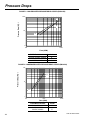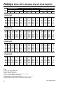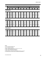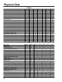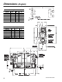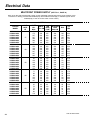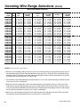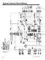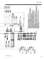
1
FORM 201.24-EG1 (701)
YCWS
WATER COOLED LIQUID CHILLER
91 TONS THROUGH 216 TONS
320 kW THROUGH 760 kW
60Hz
STYLE A
Table of Contents
Introduction .............................................................................................................................................................. 3
Specifications .......................................................................................................................................................... 4
Accessories & Options ............................................................................................................................................ 7
Design Parameters .................................................................................................................................................. 8
Pressure Drops ...................................................................................................................................................... 10
Selection Data ....................................................................................................................................................... 12
Ratings (R-22 English) ........................................................................................................................................... 14
Ratings (R-22 SI) .................................................................................................................................................... 16
Ratings- Brine (30 % Ethylene Glycol) (R-22 English) ............................................................................................ 18
Ratings- Brine (30 % Ethylene Glycol) (R-22 SI) .................................................................................................... 20
Ratings- Brine (30 % Propylene Glycol) (R-22 English) .......................................................................................... 22
Ratings- Brine (30 % Propylene Glycol) (R-22 SI) ................................................................................................... 24
Part Load Ratings .................................................................................................................................................. 26
Physical Data ........................................................................................................................................................ 28
Isolator Selection Data ........................................................................................................................................... 29
Isolator Details ....................................................................................................................................................... 30
Sound Data ............................................................................................................................................................ 31
Dimensions (English) ............................................................................................................................................. 32
Electrical Data ....................................................................................................................................................... 36
Incoming Wire Range Selections ............................................................................................................................ 39
Customer Wiring Data ............................................................................................................................................ 42
Typical Control Panel Wiring .................................................................................................................................. 44
Application Data ..................................................................................................................................................... 46
Guide Specifications .............................................................................................................................................. 47
Nomenclature
YC
W
S
0140
S
C
46
Y
A
YC= York Chiller
Design Series: A
W= Water cooled
Type Start: Y = Star-Delta
S= Screw Compressor
Nominal Capacity in Tons
Voltage Code: 17 = 200-3-60
Refrigerant C = R-22
28 = 230-3-60
40 = 380-3-60
46 = 460-3-60
58 = 575-3-60
S= Standard Efficiency
2
YORK INTERNATIONAL
Introduction
FORM 201.24-EG1
York YCWS Water Cooled Screw Chillers
YORK YCWS Water-Cooled models provide chilled water for all air conditioning applications that
use central station air handling or terminal units. They are completely self-contained and are
designed for indoor (new or retrofit) installation. Each unit includes accessible semi-hermetic
screw compressors, a liquid cooler, water cooled condenser, and a user-friendly, diagnostic
Microcomputer Control Center all mounted on a rugged steel base. The units are produced at an
ISO 9001 registered facility. The YCWS chillers have certified ratings in accordance with ARI
Standard 550/590.
YORK INTERNATIONAL
3
Specifications
GENERAL
• Each compressor will be mounted on isolator pads to
The Liquid Chiller will be completely assembled with all
interconnecting refrigerant piping and internal wiring,
ready for field installation.
COOLER
The unit will be pressure-tested, evacuated, and charged
with Refrigerant-22, and York ‘L’ (POE) synthetic oil.
There will be an operational test, with water flowing
through the cooler, to check that each control device
operates correctly.
The dual-circuit cooler will be the direct-expansion type,
with refrigerant in the tubes and chilled liquid flowing
through the baffled shell. The design working pressure
of the shell (liquid) side will be 150 PSIG (10.3 bar), and
300 PSIG (26.7 bar) for the tube (refrigerant) side.
The unit will be covered with a coat of Caribbean Blue
enamel. Units are designed in accordance with NFPA
70 (National Electric Code), U.L. and cU.L. Standards,
ASHRAE/ANSI 15 Safety Code for Mechanical Refrigeration. All units are produced at an ISO 9001 registered facility. All YCWS chillers are rated and certified in
accordance with ARI Standard 550/590 at ARI conditions.
The cooler will be constructed and tested in accordance
with the applicable sections of the ASME Pressure Vessel Code, Section VlII, Division (1). The water side will
be exempt per paragraph U-1, (c)(6).
reduce transmission of vibration to the rest of the unit.
The water baffles will be constructed of galvanized steel
to resist corrosion. The removable heads will allow access to the internally enhanced, seamless, copper tubes.
Vent and drain connections will be included.
SEMI-HERMETIC YORK SCREW COMPRESSORS
• Continuous function, microprocessor controlled, 3- way
proportional Capacity Control Valve provides regulated
output pressure independent of valve input pressure
for a stable, smooth, and precise match of compressor capacity to cooling load to 10% of chiller capacity.
• Automatic spring return of capacity control valve to
minimum load position ensures compressor starting
at minimum motor load. Internal discharge check to
prevent rotor backspin upon shutdown.
• Acoustically tuned, internal discharge gas path eliminates objectionable noise at the source, while optimizing flow for maximum performance.
• Reliable suction gas cooled, high efficiency, accessible hermetic motor with APT2000 type magnet wire
and redundant overload protection using both thermistor and current overload protection.
• Suction gas screen and serviceable, 0.5 micron full
flow oil filter within the compressor housing.
• Cast iron compressor housing precisely machined for
optimal clearances and superb efficiency. Entire compressor, from suction to discharge has a Design Working Pressure of 450psig (31 bar).
• 350W compressor body cartridge heater.
4
The cooler will be covered with 3/4" (19.1 mm ) flexible,
closed-cell, foam insulation (K = 0.25).
CONDENSER
The condenser is a cleanable thru-tube type with steel
shell, copper tubes, removable water heads, and includes
integral subcooling. Refer to PHYSICAL DATA for design working pressures. The shell will be constructed
and tested in accordance with section Vll, division 1 of
the ASME pressure-vessel code. The water side is exempt per paragraph U-1 (c) of section VlII, division 1 of
the ASME pressure-vessel code. The condenser is
equipped with relief valves and will hold the full refrigerant charge for pumpdown.
REFRIGERANT CIRCUIT
Two independent refrigerant circuits will be furnished on
each unit. All piping will be copper with brazed joints.
The liquid line will include: a shutoff valve with charging
port; sightglass with moisture indicator; thermal expansion valve; solenoid valve; and high-absorption removable-core filter drier. The entire suction line and the liquid line between the expansion valve and the cooler will
be insulated with flexible, closed-cell, foam insulation.
POWER AND CONTROL PANELS
All controls and motor starting equipment necessary for
unit operation shall be factory wired and function tested.
The panel enclosures shall be designed to NEMA 1 (IP
32) and manufactured from powder-painted galvanized
steel.
YORK INTERNATIONAL
FORM 201.24-EG1
The Power and Control Panel shall be divided into a power
section for each electrical system, a common input section and a control section.
reset after power failure, automatic system optimization
to match operating conditions, software stored in nonvolatile memory (EPROM) to eliminate chiller failure due
to AC power failure.
Each power panel shall contain:
Compressor starting contactors, control circuit
serving compressor capacity control, compressor
contactor coils and compressor motor overloads. The
compressor motor overloads contain current transformers which sense each phase, as an input to the
microprocessor, to protect the compressor motors
from damage due to: low input current, high input current, unbalanced current, single phasing, phase
reversal, and compressor locked rotor.
The common input section shall contain:
The control supply transformer providing 115V, customer relay board and control circuit switch disconnect/emergency stop device.
The microprocessor can be directly connected to a YORK
ISN Building Automation System via the standard onboard RS485 communications port. This option also provides open system compatibility with other communications networks.
Programmed Setpoints shall be retained in a lithium battery backed RTC with a memory of five years.
Display - In Imperial (°F and PSIG) or SI (°C and BAR)
units, and for each circuit:
• A liquid crystal 40 character display with text provided
on two lines and light emitting diode backlighting for
outdoor viewing.
• A color-coded, 35 button, sealed keypad with sections for Display, Entry, Setpoints, Clock, Print, Program, and Unit On/Off Switch.
• Return and leaving chilled liquid
• Day, date and time. Daily start/stop times. Holiday
and Manual Override status.
• Compressor operating hours and starts. Automatic
or manual lead/lag. Lead compressor identification.
• Run permissive status. No cooling load condition.
Compressor run status.
• Anti-recycle timer and anti-coincident start timer status per compressor.
• Suction (and suction superheat), discharge, and oil
pressures and temperatures per System.
• Percent full load compressor motor current per phase
and average per phase. Compressor capacity control valve input steps.
• Cutout status and setpoints for: supply fluid temperature, low suction pressure, high discharge pressure
and temperature, high oil temperature, low and high
current, phase rotation safety, and low leaving liquid
temperature.
• Unloading limit setpoints for high discharge pressure
and compressor motor current.
• Liquid pull-down rate sensitivity (0.5°F to 5°F [0.3°C
to 3.0°C]/minute in 0.1°F [0.05°C] increments).
• Status of: evaporator heater, load and unload timers,
chilled water pump.
• Out of range message.
• Up to 6 fault shut down conditions.
• Standard Display Language is English, with an Option for Spanish.
The standard controls shall include: brine chilling or thermal storage, automatic pumpdown, run signal contacts,
demand load limit from external building automation system input, remote reset liquid temperature reset input,
unit alarm contacts, chilled liquid pump control, automatic
Entry - Enter set point changes, cancel inputs, advance
day, change AM/PM.
Set Points - Chilled liquid temperature, chilled liquid
range, remote reset temperature range.
Clock - Time, daily or holiday start/stop schedule, manual
The control section shall contain:
On/Off rocker switch, microcomputer keypad and display, microprocessor board, I/O expansion board,
relay boards, and 24V fused power supply board.
MICROPROCESSOR CONTROLS
Fuzzy Logic control will be incorporated in the YCWS
range of chillers. Fuzzy Logic allows the control system
to monitor several key variables to provide tighter, more
stable chilled water temperature control. The control system monitors the leaving chilled water temperature to
track where it has been, where it is now, how fast it is
moving, and accurately adjusts the chiller operation in
anticipation of expected performance to minimize hunting and save energy.
The microprocessor shall have the following functions
and displays:
YORK INTERNATIONAL
5
Specifications
(Continued)
override for servicing.
Print - Operating data or system fault shutdown history
for last six faults. Printouts through an RS-232 port via a
separate printer (by others).
Program • Low leaving liquid temperature cutout, 300 to 600
second anti-recycle timer, lag compressor start time
delay, and average motor current unload point. Liquid temperature setpoint reset signal from YORK ISN
or building automation system (by others) via:
• Pulse width modulated (PWM) input for up to 40°F
(22°C) total reset as standard.
• Optional Building Automation System interface input
card for up to 20°F (11.1°C) reset using a: 4 to 20
mA, 0 to 10 Vdc input, or discrete reset input.
via the standard onboard RS485 communication port.
This Option also provides open system compatibility
with other communications networks (BACnet™ &
LONMARK™ via interface through standard onboard
485 or 232 port and an external YorkTalk Translator.
• Additional functions (password protected) for programming by a qualified service technician:
Cutouts for low suction pressure, high discharge
pressure, high oil temperature.
Refrigerant type.
High discharge pressure unload setpoint.
Compressor motor current percent limit.
• NOTE: The Standard MicroPanel can be directly connected to a YORK ISN Building Automation System
6
YORK INTERNATIONAL
Accessories & Options
ALTERNATIVE REFRIGERANTS - Contact your nearest YORK office for information and availability on alternative HFC refrigerants.
ELECTRICAL OPTIONS:
MULTIPLE POINT POWER SUPPLY CONNECTION Standard field power wiring connection on all models is Multiple
Point Power Connection to factory provided Terminal Blocks. Two
field supplied electrical power circuits with appropriate branch circuit protection provide power to each of two motor control center
cabinets, located on either side of the Control panel on the front of
the chiller. Each cabinet contains starter elements for one compressor.
Optional to the Terminal Blocks for field power connection are
Non-Fused Disconnects or Circuit Breaker Switches with external,
lockable handles.
SINGLE POINT POWER CONNECTION - (Factory Mounted) An
optional configuration for field connection of a single electrical circuit to: either Terminal Block or Non-Fused Disconnect Switch with
lockable external handle (in compliance with Article 440 of N.E.C.,
to isolate unit power supply for service). Factory wiring is provided from the Terminal Block or Disconnect Switch to Factory
supplied individual system Circuit Breakers, Non-Fused Disconnect
switch with external, lockable handle or J Class Fuses/Fuse Block
in each of the two compressor motor control centers. (Note: Single
Point Non-Fused Disconnect Switch will not be supplied with individual system Non Fused Disconnect Switches with external, lockable handles in each of the two compressor motor control centers).
65 Ka HIGH VOLTAGE PROTECTION - Non-Fused Disconnect
Switch with fuses (200 & 575V) or Circuit Breakers (230, 380, &
460V) are used for applications where customers have a requirement for single point wiring with high “fault current” withstanding
capability. This option provides between 50Ka and 65Ka withstand
protection to the equipment.
BUILDING AUTOMATION SYSTEM INTERFACE (Factory
Mounted) – Provides means to reset the leaving chilled liquid
temperature or percent full load amps (current limiting) from the
BAS (Factory Mounted):
• Printed circuit board to accept 4 to 20 milliamp, 0 to 10 VDC,
or dry contact closure input from the BAS.
• A YORK ISN Building Automation System can provide a Pulse
Width Modulated (PWM) signal direct to the standard control
panel via the standard onboard RS485 port.
FLOW SWITCH – The flow switch or its equivalent must be furnished with each unit. 150 PSIG (10.5 bar) DWP – For standard
units. Johnson Controls model F61MG-1C Vapor-proof SPDT, NEMA
4X switch (150 PSIG [10.5 bar] DWP), -20°F to 250°F- (29°C to
121°C), with 1" NPT connection for upright mounting in horizontal
pipe. (Field mounted)
DIFFERENTIAL PRESSURE SWITCH - Alternative to the above mentioned Flow Switch. Pretemco Model DPS 300A-P4OPF-82582-S
(20.7bar max working pressure). SPDT 5 amp 125/250 VAC switch.
Range: 0 - 2.8bar, deadband: 0.003 - 0.005bar, with 1/4 NPTE pressure connections.
LANGUAGE LCD AND KEYPAD - Standard display language and
YORK INTERNATIONAL
FORM 201.24-EG1
keypad is in English. Spanish is available as an option.
PRINTER KIT - Printer for obtaining printout of unit operating and
history data. (Field Mounted)
MULTIPLE UNIT SEQUENCE CONTROL (Field Mounted) - Sequencing Control with automatic unit sequencing. Necessary items
for operation and control of up to eight units with parallel water
circuits. Includes software and mixed liquid temperature sensor
(interconnecting wiring by others).
PRESSURE VESSEL CODES - Coolers and condensers can be
supplied in conformance with the following pressure codes:
A.S.M.E. (Standard)
CHICAGO CODE RELIEF VALVES (Factory Mounted) - Unit will be
provided with relief valves to meet Chicago Code requirements.
ACCESSORIES:
FLANGES (Weld Type) – Consists of 150 PSI (10.5 bar ) standard
cooler (150 lb) R.F. flanges to convert to flanged cooler-connections and includes companion flanges. (Field mounted)
FLANGES (Victaulic Type) – Consists of (2) Flange adapter for
grooved end pipe (standard 150 PSI [10.5 bar] cooler). Includes
companion flanges. (Field mounted)
VIBRATION ISOLATION:
• Neoprene Isolators – Recommended for normal installations.
Provides very good performance in most applications for the
least cost. (Field mounted)
• 1" Spring Isolators – Level adjustable, spring and cage type
isolators for mounting under the unit base rails. 1" nominal deflection may vary slightly by application. (Field mounted)
• 2" Seismic Spring Isolators – Restrained Spring-Flex Mountings
incorporate a rugged welded steel housing with vertical and
horizontal limit stops. Housings designed to withstand a minimum 1.0g accelerated force in all directions to 2". Level adjustable, deflection may vary slightly by application. (Field-mounted)
ALTERNATIVE CHILLED FLUID APPLICATIONS:
Standard water chilling application range is 40°F to 50°F (4.4°C to
10°C) Leaving Chilled Water Temperature. To protect against nuisance safety trips below 40°F (4.4°C) and reduce the possibility of
cooler damage due to freezing during chiller operation, the unit
microprocessor automatically unloads the compressors at abnormally low suction temperature (pressure) conditions , prior to safety
shutdown.
• Process Brine Option – Process or other applications requiring chilled fluid below 40°F (4.4°C) risk water freezing in the
evaporator, typically overcome by using antifreeze. For these
applications, the chiller system incorporates brine (ethylene or
propylene glycol solution), and the system design Leaving Chilled
Fluid Temperature must be provided on the order form to ensure
proper factory configuration.
• Thermal Storage Option – Thermal Storage equires special
capabilities from a chiller, including the ability to ‘charge’ an ice
storage tank, then possibly automatically reset for operation at
elevated Leaving Chilled Fluid Temperatures as required by automatic building controls. The Thermal Storage Option provides
Ice Storage duty Leaving Chilled Fluid setpoints from 25°F to
15°F( -4°C to -10°C) minimum during charge cycle, with a Reset
range of 36°F (20°C) supply fluid temperature.
7
Design Parameters
English
YCWS
Min. Cooler Water Flow - GPM
Max. Cooler Water Flow - GPM
Min. Cond. Water Flow - GPM
Max. Cond. Water Flow - GPM
Min. Lvg. Liquid Temp. - °F
Max. Lvg. Liquid Temp. - °F
Min. Ent. Cond. Water Temp - °F
Max. Ent. Cond. Water Temp - °F
Min. Equipment Room Temp. - °F
Max. Equipment Room Temp. - °F
0100SC 0120SC 0140SC 0180SC
200
200
200
260
506
506
506
695
193
193
193
330
645
645
645
1050
40
40
40
40
50
50
50
50
75
75
75
75
95
95
95
95
40
40
40
40
115
115
115
115
0200SC 0220SC 0240SC
260
300
300
695
830
830
330
330
330
1050
1050
1050
40
40
40
50
50
50
75
75
75
95
95
95
40
40
40
115
115
115
SI
YCWS
0100SC 0120SC 0140SC 0180SC
Min. Cooler Water Flow - l/sec
12.6
12.6
12.6
16.4
Max. Cooler Water Flow - l/sec
31.9
31.9
31.9
43.8
Min. Cond. Water Flow - l/sec
12.2
12.2
12.2
20.8
Max. Cond. Water Flow - l/sec
40.7
40.7
40.7
66.2
Min. Lvg. Liquid Temp. - °C
4.4
4.4
4.4
4.4
Max. Lvg. Liquid Temp. - °C
10.0
10.0
10.0
10.0
Min. Ent. Cond. Water Temp - °C
23.8
23.8
23.8
23.8
Max. Ent. Cond. Water Temp - °C
35..0
35..0
35..0
35..0
Min. Equipment Room Temp. - °C
4.4
4.4
4.4
4.4
Max. Equipment Room Temp. - °C
46.1
46.1
46.1
46.1
8
0200SC 0220SC 0240SC
16.4
18.9
18.9
43.8
52.4
52.4
20.8
20.8
20.8
66.2
66.2
66.2
4.4
4.4
4.4
10.0
10.0
10.0
23.8
23.8
23.8
35..0
35..0
35..0
4.4
4.4
4.4
46.1
46.1
46.1
YORK INTERNATIONAL
FORM 201.24-EG1
Relief
Valve
SG
Oil
Separators
Compressor
Condenser
Oil Cooling
Liquid Injection
Relief
Valve
Refrigerant Circuit No 2
TEV
Cooler
SG
SV
Oil
SV = Solenoid Valve
SG = Sight Glass
High Pressure Subcooled Liquid
Low Pressure Superheated Vapour
Low Pressure Liquid
High Pressure Superheated Vapour
TEV = Thermostatic Expansion Valve
Low-pressure liquid refrigerant enters the cooler tubes and is evaporated and superheated by the heat energy absorbed
from the chilled liquid passing through the cooler shell. Low-pressure vapor enters the compressor where pressure and
superheat are increased. High-pressure vapor is passed through the oil separator where heat is rejected to the condenser water passing through the tubes. The fully condensed and subcooled liquid leaves the condenser and enters the
expansion valve, where pressure reduction and further cooling take place. The low pressure liquid refrigerant then
returns to the cooler. Each refrigerant circuit utilizes liquid injection, maintaining efficient oil temperature operation
within the compressor.
YORK INTERNATIONAL
9
Pressure Drops
FIGURE 1 - COOLER WATER PRESSURE DROP CURVES (ENGLISH)
100
Pressure Drop (H2O)
Q
P
10
O
1
100
1000
Flow (GPM)
YCWS Model Number
Cooler
0100SC, 0120SC, 0140SC
0180SC, 0200SC
0220SC, 0240SC
O
P
Q
FIGURE 3 - CONDENSER WATER PRESSURE DROP CURVES (ENGLISH)
Pressure Drop (H2O)
100
U
10
S
1
100
1000
10000
Flow (GPM)
10
YCWS Model Number
Cooler
0100SC, 0120SC, 0140SC
0180SC, 0200SC
0220SC, 0240SC
S
U
YORK INTERNATIONAL
FORM 201.24-EG1
FIGURE 2 - COOLER WATER PRESSURE DROP CURVES (SI)
Pressure Drop (kPa)
1000
Q
100
O
P
10
1
10
100
Flow (l/s)
YCWS Model Number
Cooler
0100SC, 0120SC, 0140SC
0180SC, 0200SC
0220SC, 0240SC
O
P
Q
FIGURE 4 - CONDENSER WATER PRESSURE DROP CURVES (SI)
Pressure Drop (kPa)
1000
U
100
S
10
1
10
0100SC, 0120SC, 0140SC
0180SC, 0200SC
0220SC, 0240SC
YORK INTERNATIONAL
100
Flow (l/s)
S
U
11
Selection Data
COND FOULING FACTORS
GUIDE TO SELECTION
Complete water chilling capacity ratings for YORK YCWS
chillers are shown on the following pages to cover the
majority of job requirements. For any application beyond the scope of this Engineering Guide, consult your
nearest YORK Office.
Temp
Split
8
10
12
14
0.00025
Compr
kW
0.9998 1.0004
1.0000 1.0000
1.0001 0.9998
1.0001 0.9998
x
0.0005
Compr
kW
0.9957 1.0072
0.9959 1.0068
0.9961 1.0065
0.9965 1.0060
Tons
Tons
SELECTION RULES
1. RATINGS - YCWS 200, 230 380, 460 & 575-3-60 rating are certified in accordance with ARI standard 550/
590, at the ARI standard condition. Rating not at standard ARI conditions are rated in accordance with ARI
rating procedures. These ratings may be interpolated
but should not be extrapolated.
Note: Temperature split factors @ 95ºF Leaving Condenser Water
Temp (LCWT).
METHOD OF SELECTION
If the duty requires a 10ºF range on both the cooler and
condenser, see “Ratings”. For water ranges other than
10ºF, use the following procedure.
2. COOLING WATER QUANTITY - Ratings are based
on 10ºF chilled water range. Use the chilled water
correction factors (below) for other ranges except as
limited by water pressure drop, minimum or maximum
water flows for the cooler.
1. Determine capacity required from the following formula
3. CONDENSER WATER QUANTITY – Rating are applicable from 2 to 4 gpm/ton as limited by water pressure drop or minimum or maximum water flows for
the condenser. Using the tabulated MBH, the Cond.
GPM is calculated as follows:
2. After applying any fouling factor corrections, the actual condenser heat rejection may be determined as
follows:
MBH x 2
Cond. GPM = Cond. Water Range (ºF)
Capacity (tons) =
GPM x Chilled Water Range (ºF)
24
Heat Rejection (Btuh) = (Tons x 12,000) + (kW x 3415)
Heat Rejection (MBH) =
Heat Rejection (Btuh)
1000
= (Tons x 12) = (kW x 3.415)
4. FOULING FACTORS – Rating are based on 0.0001
evaporator and 0.00025 condenser fouling factor. For
other fouling factors, consult the table below or contact your YORK representative.
Condenser Tons =
EVAP FOULING FACTORS
Temp
Split
6
8
10
12
14
0.0001
Compr
kW
0.9692
1.0015
0.9849
1.0008
1.0000
1.0000
1.0133
0.9993
1.0248
0.9986
Tons
x
3. Determine condensing water requirements for water
cooled models as follows:
0.00025
Compr
kW
0.9972
1.0001
0.9980
1.0001
0.9982
1.0001
0.9978
1.0001
0.9979
1.0001
Tons
Cond. Water GPM =
12
Condenser Tons x 30
Condenser Water Range (ºF)
Or combine the two formulas:
Cond. Water GPM =
Note: Temperature split factors @ 44ºF Leaving Chilled Liquid Temp
(LCLT)
Heat Rejection (MBH) x 1000
15,000
MBH x 2
Condenser Water Range (ºF)
YORK INTERNATIONAL
FORM 201.24-EG1
SAMPLE SELECTION
EER =
Water Cooled Condenser (YCWS)
GIVEN – Chill 200 GPM of water from 56ºF to 44ºF and
0.0001 evaporator fouling factor with 85ºF to 95ºF condensing water available. Fouling factor of 0.0005 special field for the condenser.
FIND – The required unit size capacity, kW, EER, and
water pressure drop.
SOLUTION:
1. Chilled water range = 56ºF - 44ºF = 12ºF and correction factors are 1.0133 for Tons and 0.9993 for kW for
the cooler.
2. Capacity (tons) =
=
GPM x Chilled Water Range
24
200 x 12
= 100TR
24
Tons x 12 = 95.0 X 12 = 15.4
Kw
74
4. Determine the cond. Heat rejection as follows:
Heat Rejection (MBH)
= (Tons x 12) + (kW x 3.415)
= (95.0 x 12) + (74 x 3.415)
= 1140 + 253
= 1393
5. Determine GPM condensing water as follows:
MBH x2
GPM Condenser Water = Cond Water Range
6. From curves on pages 10 and 11, the pressure drops
with 200GPM through the cooler and 288 through the
condenser of the Model YCWS120SC
Cooler Pressure Drop at 200 GPM = 2.9ft
Condenser Pressure Drop at 288 GPM = 5.5ft
2. From the rating, a model YCWS0120SC has a capacity range required. For the cooler leaving water
temperature of 44ºF and a condenser leaving water
temperature of 95ºF, the unit capacity rating table indicates:
Tons = 110.3
KW = 86.2
EER = 15.4
Correcting for the 12ºF chilled water range and the 0.0005
condenser-fouling factor:
Tons
KW
= 110.3 x 1.0133 x 0.9961 = 111.3TR
= 86.2 x 0.9993 x 1.0065 = 86.7
The unit is suitable.
3. Determine the average full load kW and EER at 95.0
Tons
95.0 X (86.7) = 74KW
111.3
YORK INTERNATIONAL
13
Ratings
(R-22 English)
LEAVING CONDENSER WATER TEMPERATURE (°F)
LCWT
(°F)
85.0
TONS
KW
MBH
95.0
EER
TONS
KW
MBH
105.0
EER
TONS
KW
63.3
63.4
63.5
63.6
63.6
63.5
63.4
1288.0
1333.0
1379.0
1402.0
1426.0
1473.0
1522.0
17.0
17.6
18.3
18.7
19.0
19.8
20.6
84.1
87.7
91.3
93.2
95.0
98.9
102.8
71.5
71.8
72.0
72.2
72.3
72.5
72.7
1253.0
1297.0
1341.0
1364.0
1387.0
1434.0
1482.0
14.1
14.7
15.2
15.5
15.8
16.4
17.0
78.7
82.1
85.6
87.4
89.2
92.9
96.7
80.7
80.9
81.1
81.2
81.4
81.7
81.9
108.0
112.3
116.8
119.1
121.5
126.2
131.1
75.6
75.8
76.0
76.0
76.0
76.0
75.9
1553.0
1607.0
1661.0
1689.0
1717.0
1774.0
1832.0
17.1
17.8
18.5
18.8
19.2
19.9
20.7
101.7
105.9
110.3
112.5
114.7
119.3
124.0
85.6
85.9
86.2
86.3
86.5
86.7
86.9
1512.0
1564.0
1617.0
1644.0
1671.0
1727.0
1784.0
14.3
14.8
15.4
15.6
15.9
16.5
17.1
95.3
99.3
103.5
105.6
107.8
112.2
116.7
96.6
96.9
97.2
97.3
97.5
97.8
98.1
127.8
132.9
138.2
140.9
143.6
149.2
154.9
88.1
88.3
88.5
88.5
88.6
88.6
88.6
1834.0
1896.0
1960.0
1993.0
2025.0
2093.0
2161.0
17.4
18.1
18.7
19.1
19.5
20.2
21.0
120.4
125.4
130.5
133.1
135.7
141.1
146.6
99.8
100.2
100.5
100.7
100.8
101.1
101.3
1786.0
1847.0
1909.0
1940.0
1973.0
2038.0
2105.0
14.5
15.0
15.6
15.9
16.2
16.7
17.4
112.9
117.7
122.6
125.1
127.7
132.8
138.1
112.9
113.1
113.4
113.6
113.7
114.1
114.4
156.6
163.2
169.6
172.9
176.5
183.5
190.9
97.9
98.0
97.9
97.9
97.8
97.5
97.2
1473.0
1522.0
1573.0
1599.0
1626.0
1680.0
1735.0
11.8
12.3
12.8
13.0
13.3
13.8
14.3
1740.0
1798.0
1858.0
1889.0
1920.0
1983.0
2047.0
12.0
12.5
13.0
13.2
13.5
14.0
14.5
IPLV = 20.9
YCWS0180SC
40.0
42.0
44.0
45.0
46.0
48.0
50.0
11.7
12.2
12.7
12.9
13.2
13.7
14.2
IPLV = 19.3
YCWS0140SC
40.0
42.0
44.0
45.0
46.0
48.0
50.0
1219.0
1260.0
1304.0
1325.0
1348.0
1393.0
1439.0
IPLV = 18.2
YCWS0120SC
40.0
42.0
44.0
45.0
46.0
48.0
50.0
EER
IPLV = 18.8
YCWS0100SC
40.0 89.4
42.0 93.1
44.0 96.9
45.0 98.8
46.0 100.7
48.0 104.7
50.0 108.8
MBH
2213.0
2292.0
2369.0
2409.0
2452.0
2535.0
2622.0
19.2
20.0
20.8
21.2
21.7
22.6
23.6
147.7
153.9
160.3
163.6
166.5
173.6
180.5
111.5
111.8
112.0
112.1
112.2
112.4
112.5
2153.0
2229.0
2306.0
2345.0
2380.0
2466.0
2549.0
15.9
16.5
17.2
17.5
17.8
18.5
19.3
138.5
144.5
150.6
153.7
156.9
163.4
170.0
126.2
126.5
126.8
126.9
127.1
127.4
127.7
2093.0
2166.0
2240.0
2278.0
2317.0
2395.0
2476.0
13.2
13.7
14.3
14.5
14.8
15.4
16.0
NOTES:
1. Tons = Unit Cooling Capacity Output
2. kW = Compressor Input Power
3. MBH = Condenser heat rejection
4. EER = Chiller Energy Efficiency Ratio (Capacity [Tons x 12] ÷ kW)
5. LCWT = Leaving Chilled Water Temperature
6. Ratings based on 2.4 GPM cooler water per ton
7. Ratings certified in accordance with ARI Standard 550/590-98 up to 200 tons.
14
YORK INTERNATIONAL
FORM 201.24-EG1
LEAVING CONDENSER WATER TEMPERATURE (°F)
LCWT
(°F)
85.0
TONS
KW
MBH
95.0
EER
TONS
KW
MBH
105.0
EER
TONS
KW
179.1
186.3
194.0
197.8
201.7
209.6
217.7
110.1
110.2
110.1
110.1
110.0
109.8
109.4
2525.0
2611.0
2703.0
2749.0
2796.0
2890.0
2986.0
19.5
20.3
21.1
21.6
22.0
22.9
23.9
168.8
175.7
183.2
186.7
190.6
198.3
206.2
125.4
125.7
126.0
126.1
126.2
126.4
126.5
2454.0
2538.0
2629.0
2671.0
2717.0
2811.0
2906.0
16.2
16.8
17.4
17.8
18.1
18.8
19.6
158.3
165.1
171.9
175.6
179.1
186.6
194.3
142.0
142.3
142.6
142.8
143.0
143.3
143.7
195.2
203.1
211.2
215.3
219.5
228.4
237.3
121.3
121.4
121.4
121.4
121.3
121.1
120.7
2756.0
2851.0
2948.0
2997.0
3047.0
3154.0
3260.0
19.3
20.1
20.9
21.3
21.7
22.6
23.6
183.8
191.7
199.6
203.7
207.6
215.4
224.7
138.1
138.5
138.8
138.9
139.1
139.3
139.4
2677.0
2773.0
2869.0
2918.0
2966.0
3060.0
3171.0
16.0
16.6
17.3
17.6
17.9
18.6
19.3
172.5
179.7
187.5
191.2
195.4
203.4
211.5
156.2
156.6
157.0
157.2
157.4
157.8
158.2
210.6
219.2
228.1
232.6
237.2
246.5
256.1
132.7
132.9
133.0
132.9
132.9
132.7
132.4
13.4
13.9
14.5
14.8
15.0
15.6
16.2
2603.0
2691.0
2786.0
2831.0
2882.0
2980.0
3078.0
13.3
13.8
14.3
14.6
14.9
15.5
16.0
IPLV = 21.2
YCWS0240SC
40.0
42.0
44.0
45.0
46.0
48.0
50.0
2384.0
2467.0
2549.0
2594.0
2637.0
2729.0
2821.0
IPLV = 20.8
YCWS0220SC
40.0
42.0
44.0
45.0
46.0
48.0
50.0
EER
IPLV = 21.8
YCWS0200SC
40.0
42.0
44.0
45.0
46.0
48.0
50.0
MBH
2981.0
3084.0
3191.0
3245.0
3299.0
3411.0
3524.0
19.0
19.8
20.6
21.0
21.4
22.3
23.2
198.0
205.9
215.4
219.7
224.1
233.1
242.3
151.0
151.4
151.8
152.0
152.2
152.4
152.6
2891.0
2988.0
3102.0
3155.0
3208.0
3317.0
3429.0
15.7
16.3
17.0
17.3
17.7
18.4
19.1
185.9
193.9
202.3
206.5
210.8
219.4
228.3
170.7
171.2
171.6
171.9
172.1
172.6
173.1
2814.0
2911.0
3014.0
3065.0
3116.0
3222.0
3330.0
13.1
13.6
14.1
14.4
14.7
15.3
15.8
NOTES:
1. Tons = Unit Cooling Capacity Output
2. kW = Compressor Input Power
3. MBH = Condenser heat rejection
4. EER = Chiller Energy Efficiency Ratio (Capacity [Tons x 12] ÷ kW)
5. LCWT = Leaving Chilled Water Temperature
6. Ratings based on 2.4 GPM cooler water per ton
7. Ratings certified in accordance with ARI Standard 550/590-98 up to 200 tons.
YORK INTERNATIONAL
15
Ratings (R-22 SI)
LEAVING CONDENSER WATER TEMPERATURE (°C)
LCWT
(°C)
30.0
KWo
KWi
KW
35.0
KWi
40.0
COP
KWo
KW
380.0
392.0
404.0
416.0
429.0
442.0
4.9
5.1
5.3
5.5
5.7
5.9
299.5
310.8
322.4
334.4
346.5
359.0
71.6
71.8
72.1
72.3
72.5
72.7
371.0
382.0
394.0
406.0
419.0
431.0
458.0
473.0
487.0
502.0
517.0
532.0
5.0
5.2
5.3
5.5
5.7
5.9
362.1
375.6
389.5
403.6
418.2
432.9
85.7
86.0
86.3
86.5
86.7
86.9
541.0
558.0
575.0
592.0
610.0
628.0
5.1
5.2
5.4
5.6
5.8
6.0
428.9
444.9
461.2
477.8
494.9
511.9
653.0
674.0
693.0
716.0
738.0
760.0
5.6
5.8
6.0
6.2
6.4
6.7
525.2
545.2
565.5
586.3
608.8
629.2
COP
KWo
KWi
KW
COP
4.2
4.3
4.5
4.6
4.8
4.9
282.3
293.2
304.3
315.7
327.6
339.5
79.8
80.0
80.2
80.4
80.7
81.0
362.0
373.0
384.0
396.0
408.0
420.0
3.5
3.7
3.8
3.9
4.1
4.2
447.0
461.0
475.0
490.0
504.0
519.0
4.2
4.4
4.5
4.7
4.8
5.0
341.6
354.6
368.0
381.7
395.7
410.0
95.6
95.8
96.1
96.4
96.7
96.9
437.0
450.0
464.0
478.0
492.0
507.0
3.6
3.7
3.8
4.0
4.1
4.2
100.0
100.3
100.6
100.8
101.1
101.3
528.0
545.0
561.0
578.0
596.0
613.0
4.3
4.4
4.6
4.7
4.9
5.1
405.4
420.5
436.0
452.3
468.6
485.6
111.6
111.8
112.1
112.4
112.8
113.1
517.0
532.0
548.0
564.0
581.0
598.0
3.6
3.8
3.9
4.0
4.2
4.3
111.7
111.9
112.1
112.3
112.5
112.5
636.0
657.0
677.0
698.0
721.0
741.0
4.7
4.9
5.0
5.2
5.4
5.6
496.0
515.0
534.1
554.7
575.7
596.4
124.8
125.1
125.4
125.7
125.9
126.2
620.0
640.0
659.0
680.0
701.0
722.0
4.0
4.1
4.3
4.4
4.6
4.7
YCWS0100SC
5.0
6.0
7.0
8.0
9.0
10.0
316.4
328.1
340.1
352.4
365.1
377.9
64.1
64.3
64.4
64.5
64.5
64.4
YCWS0120SC
5.0
6.0
7.0
8.0
9.0
10.0
382.2
396.1
410.5
425.1
440.1
455.5
76.7
76.9
77.0
77.1
77.1
77.1
YCWS0140SC
5.0
6.0
7.0
8.0
9.0
10.0
452.5
468.9
485.7
502.9
520.5
538.6
89.3
89.5
89.7
89.8
89.9
89.9
YCWS0180SC
5.0
6.0
7.0
8.0
9.0
10.0
554.1
574.6
594.4
616.7
638.9
661.6
99.4
99.4
99.4
99.3
99.2
98.9
NOTES:
1. KWo = Unit kW Cooling Capacity Output
2. KWi = Compressor kW Input
3. COP = Coefficient of Performance
4. LCWT= Leaving Chilled Water Temperature
5. Ratings based on 0.047 l/s cooler water per kW.
16
YORK INTERNATIONAL
FORM 201.24-EG1
LEAVING CONDENSER WATER TEMPERATURE (°C)
LCWT
(°C)
30.0
KWo
KWi
35.0
40.0
KW
COP
KWo
KWi
KW
COP
KWo
KWi
KW
COP
744.0
768.0
792.0
817.0
842.0
867.0
5.7
5.9
6.1
6.3
6.6
6.8
599.6
623.4
646.6
668.4
694.6
719.3
125.6
125.9
126.1
126.3
126.4
126.5
725.0
749.0
772.0
794.0
821.0
845.0
4.8
5.0
5.1
5.3
5.5
5.7
567.2
589.0
609.7
632.8
657.8
681.8
140.4
140.7
141.0
141.3
141.6
141.9
707.0
729.0
750.0
774.0
799.0
823.0
4.0
4.2
4.3
4.5
4.6
4.8
813.0
837.0
865.0
891.0
919.0
946.0
5.6
5.8
6.0
6.2
6.5
6.7
654.5
679.1
704.3
730.1
756.5
783.6
138.3
138.6
138.9
139.2
139.4
139.5
792.0
817.0
843.0
869.0
896.0
923.0
4.7
4.9
5.1
5.3
5.4
5.6
617.7
641.4
664.2
690.2
716.4
742.5
154.5
154.9
155.2
155.6
156.0
156.4
772.0
796.0
819.0
845.0
872.0
898.0
4.0
4.1
4.3
4.4
4.6
4.8
134.7
880.0
134.9
907.0
134.9
935.0
134.9
964.0
134.8
993.0
134.5 1032.0
5.5
5.7
5.9
6.2
6.4
6.7
706.5
733.1
760.4
788.2
816.6
845.7
151.2
151.6
152.0
152.3
152.5
152.7
857.0
884.0
912.0
940.0
969.0
998.0
4.7
4.8
5.0
5.2
5.4
5.5
666.6
692.3
718.6
745.6
773.2
801.3
168.9
169.3
169.7
170.2
170.6
171.0
835.0
861.0
888.0
915.0
943.0
972.0
4.0
4.1
4.2
4.4
4.5
4.7
YCWS0200SC
5.0
6.0
7.0
8.0
9.0
10.0
632.7
657.1
681.1
705.4
730.4
756.0
111.7
111.8
111.8
111.7
111.5
111.3
YCWS0220SC
5.0
6.0
7.0
8.0
9.0
10.0
690.4
714.3
741.9
768.6
795.9
823.9
123.1
123.2
123.2
123.2
123.1
122.8
YCWS0240SC
5.0
6.0
7.0
8.0
9.0
10.0
745.5
772.8
800.9
829.6
859.0
897.9
NOTES:
1. KWo = Unit kW Cooling Capacity Output
2. KWi= Compressor kW Input
3. COP = Coefficient of Performance
4. LCWT= Leaving Chilled Water Temperature
5. Ratings based on 0.047 l/s cooler water per kW.
YORK INTERNATIONAL
17
Ratings- Brine (30 % Ethylene Glycol) (R-22 English)
LEAVING CONDENSER WATER TEMPERATURE (°F)
LCWT
(°F)
85.0
TONS
KW
95.0
MBH
EER
TONS
757.0
818.0
891.0
977.0
1080.0
1194.0
1280.0
8.9
10.0
11.2
12.5
14.0
15.6
16.8
42.2
47.2
53.0
59.7
67.8
76.7
83.5
916.0
989.0
1076.0
1179.0
1302.0
1438.0
1540.0
9.0
10.1
11.3
12.6
14.1
15.7
17.0
1083.0
1169.0
1272.0
1393.0
1537.0
1697.0
1818.0
1288.0
1403.0
1511.0
1680.0
1859.0
2059.0
2206.0
KW
105.0
MBH
EER
TONS
KW
MBH
EER
72.0
70.5
70.1
70.1
70.3
71.0
71.5
751.0
807.0
875.0
955.0
1053.0
1162.0
1245.0
7.0
8.0
9.1
10.2
11.6
13.0
14.0
38.6
43.4
49.0
55.4
63.1
71.6
78.1
85.7
82.8
81.4
80.5
80.2
80.4
80.6
755.0
803.0
865.0
939.0
1030.0
1133.0
1212.0
5.4
6.3
7.2
8.3
9.4
10.7
11.6
51.3
57.4
64.3
72.4
82.0
92.7
100.7
86.0
84.3
83.9
83.9
84.2
85.0
85.5
909.0
976.0
1057.0
1154.0
1271.0
1402.0
1500.0
7.2
8.2
9.2
10.3
11.7
13.1
14.1
47.2
52.9
59.6
67.3
76.4
86.6
94.4
101.8
98.7
97.2
96.4
96.0
96.3
96.6
913.0
972.0
1046.0
1136.0
1245.0
1368.0
1462.0
5.6
6.4
7.4
8.4
9.6
10.8
11.7
9.2
10.3
11.5
12.8
14.3
16.0
17.2
61.0
68.2
76.3
85.8
97.2
109.7
119.2
100.4
98.4
98.0
98.0
98.3
99.1
99.8
1075.0
1154.0
1250.0
1364.0
1501.0
1654.0
1770.0
7.3
8.3
9.4
10.5
11.9
13.3
14.3
56.2
63.0
70.8
79.9
90.7
102.7
111.8
118.5
115.0
113.4
112.5
112.2
112.5
112.8
1078.0
1148.0
1236.0
1342.0
1471.0
1616.0
1726.0
5.7
6.6
7.5
8.5
9.7
11.0
11.9
10.0
11.3
12.4
14.1
15.8
17.7
19.1
74.9
83.2
93.4
104.9
119.7
135.4
146.8
111.4
109.7
109.4
109.6
110.0
110.9
111.5
1279.0
1373.0
1494.0
1632.0
1811.0
2003.0
2142.0
8.1
9.1
10.2
11.5
13.0
14.6
15.8
68.8
76.9
88.2
97.3
110.0
126.7
138.0
130.6
127.4
125.9
125.4
125.2
125.7
126.2
1271.0
1357.0
1488.0
1595.0
1747.0
1949.0
2087.0
6.3
7.2
8.4
9.3
10.5
12.1
13.1
YCWS0100SC
16.0
20.0
24.0
28.0
32.0
36.0
40.0
45.6
50.9
56.9
63.9
72.3
81.7
88.7
61.6
60.9
61.2
61.6
62.1
62.8
63.2
YCWS0120SC
16.0 55.4
20.0 61.7
24.0 68.9
28.0 77.3
32.0 87.4
36.0 98.5
40.0 106.9
73.7
72.9
73.2
73.7
74.3
75.1
75.6
YCWS0140SC
16.0 65.8
20.0 73.2
24.0 81.7
28.0 91.7
32.0 103.5
36.0 116.5
40.0 126.5
86.0
85.2
85.4
85.9
86.6
87.5
88.1
YCWS0180SC
16.0
20.0
24.0
28.0
32.0
36.0
40.0
80.0
89.9
98.8
112.7
127.4
143.8
156.0
96.1
95.3
95.6
96.2
96.8
97.6
97.9
NOTES:
1. Tons = Unit Cooling Capacity Output
2. kW = Compressor Input Power
3. MBH = Condenser heat rejection
4. EER = Chiller Energy Efficiency Ratio (Capacity [Tons x 12] ÷ kW)
5. LCWT = Leaving Chilled Water Temperature
6. Ratings based on 2.4 GPM cooler water per ton
7. Ratings certified in accordance with ARI Standard 550/590-98 up to 200 tons.
8. For ratings other than 30% glycol, refer to the design 03 dxchill program.
18
YORK INTERNATIONAL
FORM 201.24-EG1
LEAVING CONDENSER WATER TEMPERATURE (°F)
LCWT
(°F)
85.0
TONS
KW
95.0
MBH
105.0
MBH
EER
TONS
KW
EER
TONS
KW
MBH
EER
1476.0
1599.0
1744.0
1915.0
2119.0
2346.0
2515.0
10.2
11.5
12.8
14.3
16.1
18.0
19.4
85.8
94.5
107.3
120.7
136.8
154.7
168.1
125.0
123.3
123.0
123.3
123.8
124.8
125.4
1456.0
1555.0
1707.0
1869.0
2064.0
2282.0
2445.0
8.2
9.2
10.5
11.8
13.3
14.9
16.1
78.7
87.6
99.6
112.4
127.7
144.8
157.8
146.1
142.8
141.4
140.8
140.8
141.4
141.9
1443.0
1538.0
1678.0
1830.0
2013.0
2220.0
2378.0
1609.0
1726.0
1905.0
2091.0
2312.0
2561.0
2744.0
10.1
11.3
12.7
14.2
15.9
17.8
19.2
93.1
103.2
116.8
131.5
145.8
168.5
183.2
137.4
135.4
135.2
135.5
136.0
137.3
138.1
1586.0
1701.0
1862.0
2041.0
2213.0
2491.0
2670.0
8.1
9.1
10.4
11.6
12.9
14.7
15.9
85.3
95.1
108.3
122.4
139.1
157.8
171.8
160.6
157.0
155.4
154.8
154.8
155.6
156.2
1572.0
1677.0
1830.0
1997.0
2197.0
2424.0
2595.0
6.4
7.3
8.4
9.5
10.8
12.2
13.2
1745.0
1889.0
2060.0
2262.0
2502.0
2764.0
2963.0
10.0
11.3
12.5
14.0
15.7
17.5
18.9
98.3
112.2
126.0
141.8
160.8
181.7
197.1
150.6
148.0
147.8
148.1
148.8
150.1
150.9
1693.0
1852.0
2016.0
2207.0
2437.0
2692.0
2880.0
7.8
9.1
10.2
11.5
13.0
14.5
15.7
90.0
103.5
116.8
132.0
146.2
170.1
185.3
176.4
171.5
169.9
169.2
169.2
170.0
170.7
1682.0
1827.0
1982.0
2161.0
2332.0
2621.0
2806.0
6.1
7.2
8.3
9.4
10.4
12.0
13.0
YCWS0200SC
16.0
20.0
24.0
28.0
32.0
36.0
40.0
92.3
102.8
114.8
128.8
145.7
164.3
178.3
108.0
107.2
107.6
108.2
108.9
109.7
110.1
6.5
7.4
8.5
9.6
10.9
12.3
13.3
YCWS0220SC
16.0
20.0
24.0
28.0
32.0
36.0
40.0
100.3
110.4
125.2
140.4
158.6
179.0
194.2
118.7
117.7
118.3
119.0
119.8
120.8
121.3
YCWS0240SC
16.0
20.0
24.0
28.0
32.0
36.0
40.0
108.6
120.8
134.9
151.5
171.3
192.7
209.1
129.7
128.7
129.3
130.1
131.0
132.2
132.7
NOTES:
1. Tons = Unit Cooling Capacity Output
2. kW = Compressor Input Power
3. MBH = Condenser heat rejection
4. EER = Chiller Energy Efficiency Ratio (Capacity [Tons x 12] ÷ kW)
5. LCWT = Leaving Chilled Water Temperature
6. Ratings based on 2.4 GPM cooler water per ton
7. Ratings certified in accordance with ARI Standard 550/590-98 up to 200 tons.
8. For ratings other than 30% glycol, refer to the design 03 dxchill program.
YORK INTERNATIONAL
19
Ratings- Brine (30 % Ethylene Glycol) (R-22 SI)
LEAVING CONDENSER WATER TEMPERATURE (°C)
LCWT
(°C)
30.0
KWo
KWi
KW
35.0
KWi
40.0
COP
KWo
KW
228.0
245.0
265.0
288.0
315.0
346.0
369.0
2.7
3.0
3.3
3.6
4.0
4.5
4.8
155.1
171.7
190.7
212.7
238.3
267.4
288.7
71.1
70.3
70.1
70.1
70.3
70.9
71.4
226.0
242.0
260.0
282.0
308.0
338.0
360.0
276.0
296.0
320.0
348.0
380.0
417.0
444.0
2.7
3.0
3.3
3.7
4.1
4.5
4.8
188.6
208.7
231.4
257.5
288.3
323.1
348.2
84.9
84.1
83.9
83.9
84.2
84.9
85.4
326.0
350.0
378.0
411.0
449.0
492.0
524.0
2.8
3.1
3.4
3.7
4.1
4.6
4.9
224.3
247.9
274.7
305.5
341.7
382.5
412.3
390.0
420.0
453.0
496.0
543.0
597.0
636.0
3.0
3.4
3.7
4.1
4.5
5.0
5.4
274.6
302.2
335.0
375.6
420.6
472.0
508.6
COP
KWo
KWi
KW
COP
2.2
2.4
2.7
3.0
3.4
3.8
4.0
141.7
159.7
177.9
198.8
223.4
251.3
271.8
82.9
80.9
79.9
79.3
79.1
79.3
79.6
273.0
292.0
315.0
341.0
372.0
408.0
433.0
2.2
2.5
2.8
3.1
3.4
3.8
4.1
175.1
194.4
216.2
241.3
270.7
304.1
328.6
98.4
96.6
95.5
95.0
94.7
95.1
95.3
99.1
98.2
97.9
98.0
98.3
99.1
99.6
323.0
346.0
372.0
403.0
440.0
481.0
511.0
2.3
2.5
2.8
3.1
3.5
3.9
4.1
208.7
231.2
256.9
286.5
321.2
360.5
389.1
114.6
112.7
111.5
110.9
110.7
111.1
111.3
323.0
343.0
368.0
397.0
431.0
471.0
500.0
1.8
2.1
2.3
2.6
2.9
3.3
3.5
110.2
109.6
109.4
109.6
110.0
110.9
111.4
384.0
411.0
444.0
485.0
530.0
582.0
620.0
2.5
2.8
3.1
3.4
3.8
4.3
4.6
255.6
283.7
315.6
347.8
389.2
444.7
480.5
126.6
124.9
124.0
123.7
123.6
124.1
124.5
382.0
408.0
439.0
471.0
512.0
568.0
605.0
2.0
2.3
2.5
2.8
3.2
3.6
3.9
YCWS0100SC
-8.0
-6.0
-4.0
-2.0
0.0
2.0
4.0
166.2
183.7
203.3
226.1
252.8
283.1
305.1
61.9
61.8
62.0
62.4
62.9
63.5
64.0
224.0
240.0
257.0
278.0
302.0
330.0
351.0
1.7
2.0
2.2
2.5
2.8
3.2
3.4
YCWS0120SC
-8.0
-6.0
-4.0
-2.0
0.0
2.0
4.0
201.9
222.6
246.2
273.6
305.4
341.4
367.7
74.1
74.0
74.3
74.7
75.2
76.0
76.5
273.0
291.0
311.0
336.0
365.0
399.0
424.0
1.8
2.0
2.3
2.5
2.9
3.2
3.5
YCWS0140SC
-8.0
-6.0
-4.0
-2.0
0.0
2.0
4.0
239.8
264.2
292.1
324.1
361.8
404.1
435.1
86.5
86.4
86.7
87.1
87.7
88.6
89.1
YCWS0180SC
-8.0
-6.0
-4.0
-2.0
0.0
2.0
4.0
293.8
323.8
356.1
398.5
445.5
498.7
537.1
96.7
96.7
97.0
97.5
98.1
98.9
99.2
NOTES:
1. KWo = Unit kW Cooling Capacity Output
2. KWi = Compressor kW Input
3. COP = Coefficient of Performance
4. LCWT= Leaving Chilled Water Temperature
5. Ratings based on 0.047 l/s cooler water per kW.
6. For ratings other than 30% glycol, refer to the design 03 dxchill program.
20
YORK INTERNATIONAL
FORM 201.24-EG1
LEAVING CONDENSER WATER TEMPERATURE (°C)
LCWT
(°C)
30.0
KWo
KWi
35.0
40.0
KW
COP
KWo
KWi
KW
COP
KWo
KWi
KW
COP
445.0
479.0
519.0
565.0
619.0
680.0
724.0
3.1
3.4
3.8
4.2
4.6
5.1
5.5
311.0
348.0
386.2
429.6
481.0
539.1
581.6
123.8
123.1
123.0
123.3
123.8
124.7
125.3
434.0
471.0
509.0
553.0
604.0
663.0
706.0
2.5
2.8
3.1
3.5
3.9
4.3
4.6
289.7
324.9
361.1
403.1
452.3
508.2
549.0
141.9
140.1
139.3
138.9
138.9
139.6
140.1
431.0
465.0
500.0
542.0
591.0
647.0
689.0
2.0
2.3
2.6
2.9
3.3
3.6
3.9
485.0
523.0
566.0
617.0
675.0
743.0
791.0
3.1
3.4
3.7
4.1
4.6
5.1
5.4
0.0
378.8
421.1
468.0
513.0
587.5
633.7
0.0
135.2
135.2
135.6
136.0
137.2
137.9
468.0
514.0
556.0
603.0
649.0
724.0
771.0
0.0
2.8
3.1
3.5
3.8
4.3
4.6
318.2
353.0
393.0
438.8
492.7
553.6
598.1
155.8
154.0
153.1
152.7
152.8
153.6
154.1
474.0
507.0
546.0
591.0
645.0
707.0
752.0
2.0
2.3
2.6
2.9
3.2
3.6
3.9
525.0
566.0
613.0
667.0
731.0
802.0
853.0
3.0
3.3
3.7
4.1
4.5
5.0
5.4
363.9
408.9
453.6
504.9
565.4
633.4
681.9
148.8
147.8
147.8
148.1
148.8
150.0
150.8
512.0
556.0
601.0
653.0
714.0
783.0
832.0
2.5
2.8
3.1
3.4
3.8
4.2
4.5
329.5
381.1
424.1
473.4
531.4
597.0
644.5
171.4
168.4
167.3
166.9
167.0
167.9
168.5
501.0
549.0
591.0
640.0
698.0
764.0
813.0
1.9
2.3
2.5
2.8
3.2
3.6
3.8
YCWS0200SC
-8.0
-6.0
-4.0
-2.0
0.0
2.0
4.0
336.2
371.1
410.2
455.6
509.1
569.6
612.8
108.7
108.7
109.1
109.7
110.3
111.1
111.5
YCWS0220SC
-8.0
-6.0
-4.0
-2.0
0.0
2.0
4.0
366.2
404.0
446.9
496.6
554.4
620.9
668.4
119.5
119.5
120.0
120.7
121.4
122.4
122.9
YCWS0240SC
-8.0
-6.0
-4.0
-2.0
0.0
2.0
4.0
395.3
436.1
482.0
535.8
598.6
668.8
719.2
130.6
130.6
131.1
131.9
132.7
133.8
134.4
NOTES:
1. KWo = Unit kW Cooling Capacity Output
2. KWi = Compressor kW Input
3. COP = Coefficient of Performance
4. LCWT= Leaving Chilled Water Temperature
5. Ratings based on 0.047 l/s cooler water per kW.
6. For ratings other than 30% glycol, refer to the design 03 dxchill program.
YORK INTERNATIONAL
21
Ratings- Brine (30 % Propylene Glycol) (R-22 English)
LEAVING CONDENSER WATER TEMPERATURE (°F)
LCWT
(°F)
85.0
TONS
KW
95.0
MBH
105.0
MBH
EER
TONS
KW
EER
TONS
KW
MBH
EER
755.0
815.0
888.0
973.0
1075.0
1189.0
1275.0
8.9
10.0
11.1
12.4
13.9
15.5
16.8
42.0
47.0
52.7
59.4
67.4
76.3
83.0
72.1
70.5
70.1
70.1
70.3
70.9
71.4
749.0
804.0
872.0
952.0
1049.0
1157.0
1240.0
7.0
8.0
9.0
10.2
11.5
12.9
14.0
38.4
43.3
48.8
55.1
62.8
71.2
77.7
85.8
82.8
81.4
80.6
80.2
80.4
80.6
754.0
802.0
863.0
936.0
1026.0
1129.0
1207.0
5.4
6.3
7.2
8.2
9.4
10.6
11.6
912.0
984.0
1071.0
1173.0
1295.0
1431.0
1533.0
9.0
10.1
11.2
12.5
14.0
15.7
16.9
51.0
57.0
63.9
71.9
81.5
92.1
100.1
86.1
84.3
83.9
83.9
84.2
84.9
85.5
906.0
972.0
1053.0
1149.0
1265.0
1395.0
1493.0
7.1
8.1
9.1
10.3
11.6
13.0
14.1
46.9
52.6
59.2
66.9
76.0
86.1
93.9
102.0
98.8
97.3
96.4
96.0
96.3
96.6
910.0
968.0
1042.0
1131.0
1239.0
1362.0
1456.0
5.5
6.4
7.3
8.3
9.5
10.7
11.7
1078.0
1163.0
1265.0
1386.0
1529.0
1688.0
1808.0
9.1
10.3
11.4
12.7
14.3
15.9
17.1
60.7
67.7
75.8
85.3
96.6
109.0
118.5
100.4
98.5
98.0
98.0
98.3
99.1
99.7
1070.0
1149.0
1244.0
1357.0
1494.0
1646.0
1762.0
7.2
8.3
9.3
10.4
11.8
13.2
14.3
55.8
62.6
70.4
79.4
90.1
102.0
111.1
118.7
115.1
113.5
112.6
112.2
112.5
112.8
1074.0
1144.0
1231.0
1336.0
1464.0
1608.0
1718.0
5.6
6.5
7.4
8.5
9.6
10.9
11.8
1294.0
1400.0
1528.0
1677.0
1855.0
2053.0
2201.0
10.1
11.3
12.6
14.0
15.7
17.6
19.1
74.7
83.5
93.5
105.3
119.3
134.9
146.7
111.5
109.6
109.4
109.6
110.0
110.9
111.5
1276.0
1376.0
1495.0
1637.0
1807.0
1998.0
2141.0
8.0
9.1
10.3
11.5
13.0
14.6
15.8
69.1
77.2
86.8
98.0
111.4
126.3
137.6
130.5
127.3
126.0
125.3
125.2
125.7
126.2
1274.0
1360.0
1471.0
1604.0
1764.0
1945.0
2082.0
6.4
7.3
8.3
9.4
10.7
12.1
13.1
YCWS0100SC
16.0
20.0
24.0
28.0
32.0
36.0
40.0
45.4
50.6
56.6
63.6
72.0
81.3
88.3
61.6
60.9
61.2
61.6
62.1
62.8
63.2
YCWS0120SC
16.0 55.1
20.0 61.3
24.0 68.5
28.0 76.8
32.0 86.8
36.0 97.9
40.0 106.3
73.7
72.9
73.2
73.7
74.2
75.1
75.6
YCWS0140SC
16.0 65.4
20.0 72.8
24.0 81.2
28.0 91.1
32.0 102.8
36.0 115.8
40.0 125.7
86.0
85.1
85.4
85.9
86.5
87.5
88.0
YCWS0180SC
16.0
20.0
24.0
28.0
32.0
36.0
40.0
80.5
89.6
100.1
112.4
127.0
143.4
155.6
96.1
95.3
95.7
96.2
96.8
97.6
97.9
NOTES:
1. Tons = Unit Cooling Capacity Output
2. kW = Compressor Input Power
3. MBH = Condenser heat rejection
4. EER = Chiller Energy Efficiency Ratio (Capacity [Tons x 12] ÷ kW)
5. LCWT = Leaving Chilled Water Temperature
6. Ratings based on 2.4 GPM cooler water per ton
7. Ratings certified in accordance with ARI Standard 550/590-98 up to 200 tons.
8. For ratings other than 30% glycol, refer to the design 03 dxchill program.
22
YORK INTERNATIONAL
FORM 201.24-EG1
LEAVING CONDENSER WATER TEMPERATURE (°F)
LCWT
(°F)
85.0
TONS
KW
95.0
105.0
MBH
EER
TONS
KW
MBH
EER
TONS
KW
MBH
EER
1474.0
1596.0
1740.0
1910.0
2113.0
2338.0
2506.0
10.2
11.5
12.8
14.2
16.0
17.9
19.4
85.5
95.5
107.0
120.4
136.4
154.1
167.5
125.1
123.2
123.0
123.2
123.7
124.7
125.4
1453.0
1566.0
1704.0
1865.0
2058.0
2275.0
2438.0
8.2
9.3
10.4
11.7
13.2
14.8
16.0
78.7
88.3
99.3
112.1
127.4
144.3
157.2
146.0
142.7
141.4
140.8
140.8
141.4
141.9
1443.0
1547.0
1674.0
1825.0
2008.0
2214.0
2371.0
6.5
7.4
8.4
9.6
10.9
12.2
13.3
1609.0
1743.0
1900.0
2086.0
2307.0
2553.0
2738.0
10.1
11.4
12.7
14.1
15.9
17.7
19.2
93.1
104.0
116.5
131.2
148.6
168.0
182.5
137.4
135.4
135.2
135.5
136.1
137.3
138.0
1586.0
1710.0
1860.0
2036.0
2248.0
2484.0
2661.0
8.1
9.2
10.3
11.6
13.1
14.7
15.9
85.6
96.1
108.1
122.1
138.8
157.3
171.3
160.5
156.8
155.4
154.8
154.8
155.5
156.1
1575.0
1688.0
1828.0
1993.0
2193.0
2418.0
2589.0
6.4
7.4
8.3
9.5
10.8
12.1
13.2
1742.0
1885.0
2056.0
2256.0
2494.0
2758.0
2959.0
10.0
11.2
12.5
13.9
15.6
17.5
18.9
100.4
112.2
125.7
141.4
160.3
181.1
196.9
150.2
148.0
147.8
148.1
148.8
150.0
150.9
1717.0
1851.0
2012.0
2203.0
2431.0
2685.0
2878.0
8.0
9.1
10.2
11.5
12.9
14.5
15.7
92.3
103.7
116.6
131.6
149.6
169.5
184.5
175.6
171.5
169.9
169.2
169.2
170.0
170.7
1707.0
1829.0
1979.0
2157.0
2372.0
2614.0
2797.0
6.3
7.3
8.2
9.3
10.6
12.0
13.0
YCWS0200SC
16.0
20.0
24.0
28.0
32.0
36.0
40.0
92.1
102.5
114.5
128.4
145.1
163.7
177.5
108.0
107.2
107.6
108.2
108.8
109.7
110.1
YCWS0220SC
16.0
20.0
24.0
28.0
32.0
36.0
40.0
100.3
111.8
124.7
140.0
158.2
178.4
193.7
118.7
117.8
118.3
119.0
119.8
120.8
121.3
YCWS0240SC
16.0
20.0
24.0
28.0
32.0
36.0
40.0
108.3
120.5
134.6
151.0
170.6
192.2
208.8
129.7
128.7
129.3
130.1
131.0
132.1
132.7
NOTES:
1. Tons = Unit Cooling Capacity Output
2. kW = Compressor Input Power
3. MBH = Condenser heat rejection
4. EER = Chiller Energy Efficiency Ratio (Capacity [Tons x 12] ÷ kW)
5. LCWT = Leaving Chilled Water Temperature
6. Ratings based on 2.4 GPM cooler water per ton
7. Ratings certified in accordance with ARI Standard 550/590-98 up to 200 tons.
8. For ratings other than 30% glycol, refer to the design 03 dxchill program.
YORK INTERNATIONAL
23
Ratings- Brine (30 % Propylene Glycol) (R-22 SI)
LEAVING CONDENSER WATER TEMPERATURE (°C)
LCWT
(°C)
30.0
KWo
KWi
KW
35.0
KWi
40.0
COP
KWo
KW
227.0
244.0
264.0
287.0
314.0
345.0
367.0
2.7
3.0
3.3
3.6
4.0
4.4
4.8
154.4
171.0
189.8
211.6
237.1
266.0
287.2
71.1
70.3
70.1
70.1
70.3
70.9
71.3
225.0
241.0
259.0
281.0
307.0
336.0
358.0
274.0
295.0
319.0
346.0
378.0
415.0
442.0
2.7
3.0
3.3
3.6
4.0
4.5
4.8
187.5
207.4
230.0
256.0
286.5
321.1
346.4
85.0
84.2
83.9
83.9
84.2
84.9
85.4
324.0
348.0
376.0
409.0
447.0
490.0
521.0
2.8
3.0
3.4
3.7
4.1
4.5
4.9
222.9
246.3
272.9
303.5
339.6
380.1
409.8
390.0
420.0
454.0
496.0
542.0
595.0
634.0
3.0
3.4
3.7
4.1
4.5
5.0
5.4
274.5
303.5
336.6
374.8
419.7
470.6
507.5
COP
KWo
KWi
KW
COP
2.2
2.4
2.7
3.0
3.4
3.8
4.0
143.1
159.1
177.2
197.9
222.3
250.1
270.5
82.7
81.0
80.0
79.4
79.1
79.3
79.6
272.0
291.0
313.0
340.0
370.0
406.0
431.0
2.2
2.5
2.7
3.1
3.4
3.8
4.1
174.1
193.3
214.9
239.9
269.1
302.3
326.7
98.5
96.7
95.6
95.0
94.8
95.1
95.3
99.2
98.3
97.9
98.0
98.3
99.0
99.6
322.0
344.0
370.0
401.0
437.0
479.0
509.0
2.3
2.5
2.8
3.1
3.5
3.8
4.1
207.2
229.8
255.3
284.7
319.2
358.2
386.8
114.7
112.8
111.6
110.9
110.7
111.0
111.3
322.0
342.0
366.0
395.0
429.0
469.0
498.0
1.8
2.0
2.3
2.6
2.9
3.2
3.5
110.2
109.5
109.4
109.6
110.0
110.8
111.4
384.0
413.0
446.0
484.0
529.0
581.0
618.0
2.5
2.8
3.1
3.4
3.8
4.3
4.6
255.8
279.0
315.0
351.6
394.7
443.4
479.1
126.6
125.2
124.0
123.6
123.6
124.1
124.5
382.0
404.0
439.0
475.0
518.0
567.0
603.0
2.0
2.2
2.5
2.8
3.2
3.6
3.9
YCWS0100SC
-8.0
-6.0
-4.0
-2.0
0.0
2.0
4.0
165.5
182.8
202.3
224.9
251.5
281.6
303.5
61.9
61.8
62.0
62.4
62.9
63.5
63.9
225.0
240.0
257.0
277.0
301.0
329.0
350.0
1.7
2.0
2.2
2.5
2.8
3.2
3.4
YCWS0120SC
-8.0
-6.0
-4.0
-2.0
0.0
2.0
4.0
200.6
221.3
244.8
271.7
303.5
339.5
365.6
74.1
74.0
74.2
74.7
75.2
75.9
76.4
272.0
290.0
310.0
334.0
363.0
397.0
422.0
1.8
2.0
2.3
2.5
2.8
3.2
3.4
YCWS0140SC
-8.0
-6.0
-4.0
-2.0
0.0
2.0
4.0
238.2
262.5
290.1
322.0
359.3
401.7
432.3
86.5
86.4
86.6
87.1
87.6
88.5
89.0
YCWS0180SC
-8.0
-6.0
-4.0
-2.0
0.0
2.0
4.0
293.4
323.5
357.8
399.0
444.1
497.0
535.2
96.7
96.7
97.0
97.6
98.1
98.8
99.2
NOTES:
1. KWo = Unit kW Cooling Capacity Output
2. KWi = Compressor kW Input
3. COP = Coefficient of Performance
4. LCWT= Leaving Chilled Water Temperature
5. Ratings based on 0.047 l/s cooler water per kW.
6. For ratings other than 30% glycol, refer to the design 03 dxchill program.
24
YORK INTERNATIONAL
FORM 201.24-EG1
LEAVING CONDENSER WATER TEMPERATURE (°C)
LCWT
(°C)
30.0
KWo
KWi
35.0
40.0
KW
COP
KWo
KWi
KW
COP
KWo
KWi
KW
COP
444.0
478.0
518.0
563.0
617.0
678.0
722.0
3.1
3.4
3.8
4.1
4.6
5.1
5.5
314.2
347.4
385.2
428.4
479.5
537.5
579.5
123.7
123.1
123.0
123.3
123.7
124.7
125.2
438.0
470.0
508.0
551.0
603.0
662.0
704.0
2.5
2.8
3.1
3.5
3.9
4.3
4.6
292.3
324.2
360.4
402.0
451.1
506.6
547.3
141.8
140.1
139.3
138.9
138.9
139.6
140.1
434.0
464.0
499.0
541.0
590.0
646.0
687.0
2.1
2.3
2.6
2.9
3.3
3.6
3.9
485.0
523.0
565.0
615.0
674.0
741.0
789.0
3.1
3.4
3.7
4.1
4.6
5.1
5.4
342.1
378.6
419.8
466.9
522.6
585.8
631.4
136.0
135.2
135.2
135.5
136.1
137.2
137.9
478.0
513.0
555.0
602.0
658.0
723.0
769.0
2.5
2.8
3.1
3.4
3.8
4.3
4.6
318.1
353.7
392.4
438.0
491.4
552.0
596.3
155.8
154.0
153.1
152.7
152.8
153.6
154.1
474.0
507.0
545.0
590.0
644.0
705.0
750.0
2.0
2.3
2.6
2.9
3.2
3.6
3.9
525.0
565.0
612.0
666.0
729.0
800.0
852.0
3.0
3.3
3.7
4.1
4.5
5.0
5.4
368.7
408.0
452.3
503.5
563.5
631.6
681.1
148.6
147.8
147.8
148.1
148.8
150.0
150.7
517.0
555.0
600.0
651.0
712.0
781.0
831.0
2.5
2.8
3.1
3.4
3.8
4.2
4.5
343.0
380.5
423.1
472.2
529.8
595.0
642.4
170.4
168.4
167.4
166.9
167.0
167.8
168.4
513.0
549.0
590.0
639.0
696.0
762.0
810.0
2.0
2.3
2.5
2.8
3.2
3.5
3.8
YCWS0200SC
-8.0
-6.0
-4.0
-2.0
0.0
2.0
4.0
335.6
370.0
409.1
454.2
507.3
567.6
610.7
108.7
108.7
109.1
109.7
110.3
111.1
111.5
YCWS0220SC
-8.0
-6.0
-4.0
-2.0
0.0
2.0
4.0
365.6
403.8
445.8
495.1
553.1
618.8
666.3
119.5
119.5
120.0
120.6
121.3
122.3
122.8
YCWS0240SC
-8.0
-6.0
-4.0
-2.0
0.0
2.0
4.0
394.4
434.9
480.9
534.1
596.4
666.7
718.5
130.6
130.6
131.1
131.8
132.7
133.8
134.4
NOTES:
1. KWo = Unit kW Cooling Capacity Output
2. KWi = Compressor kW Input
3. COP = Coefficient of Performance
4. LCWT= Leaving Chilled Water Temperature
5. Ratings based on 0.047 l/s cooler water per kW.
6. For ratings other than 30% glycol, refer to the design 03 dxchill program.
YORK INTERNATIONAL
25
Part Load Ratings
English
Load
1.0
0.8
0.5
0.3
YCWS0100SC
Tons
kW
91.3
72.0
68.5
51.5
45.7
24.5
22.8
17.4
IPLV: 18.8
EER
15.2
16.0
22.3
15.8
Load
1.0
0.8
0.5
0.3
YCWS0200SC
Tons
kW
183.2
126.0
137.4
89.5
91.6
42.1
45.8
30.4
IPLV: 21.8
Load
1.0
0.8
0.5
0.3
YCWS0120SC
Tons
kW
110.3
86.2
82.7
61.4
55.1
31.3
27.6
23.4
IPLV: 18.2
EER
15.4
16.2
21.2
14.1
Load
1.0
0.8
0.5
0.3
YCWS0220SC
Tons
kW
199.6
138.8
149.7
98.6
99.8
48.9
49.9
36.1
IPLV: 20.8
Load
1.0
0.8
0.5
0.3
YCWS0140SC
Tons
kW
130.5
100.5
97.9
71.4
65.3
34.3
32.6
24.5
IPLV: 19.3
EER
15.6
16.5
22.8
16.0
Load
1.0
0.8
0.5
0.3
YCWS0240SC
Tons
kW
215.4
151.8
161.5
107.8
107.7
51.1
53.8
37.0
IPLV: 21.2
Load
1.0
0.8
0.5
0.3
YCWS0180SC
Tons
kW
160.3
112.0
120.2
79.4
80.2
39.2
40.1
28.7
IPLV: 20.9
EER
17.2
18.2
24.6
16.8
EER
17.5
18.4
26.1
18.1
EER
17.3
18.2
24.5
16.6
EER
17.0
18.0
25.3
17.5
Rated in accordance with ARI Standard 550/590
26
YORK INTERNATIONAL
FORM 201.24-EG1
SI
Load
100%
75%
50%
25%
YCWS0100SC
kWo
kWi
321.1
72.0
240.8
51.5
160.6
24.5
80.3
17.4
5.51
COP
4.5
4.7
6.5
4.6
Load
100%
75%
50%
25%
YCWS0120SC
kWo
kWi
387.9
86.2
290.9
61.4
193.9
31.3
97.0
23.4
5.32
Load
100%
75%
50%
25%
YCWS0200SC
kWo
kWi
644.4
126.0
483.3
89.5
322.2
42.1
161.1
30.4
6.40
COP
5.1
5.4
7.7
5.3
COP
4.5
4.7
6.2
4.1
Load
100%
75%
50%
25%
YCWS0220SC
kWo
kWi
702.2
138.8
526.6
98.6
351.1
48.9
175.5
36.1
6.11
COP
5.1
5.3
7.2
4.9
Load
100%
75%
50%
25%
YCWS0140SC
kWo
kWi
459.0
100.5
344.2
71.4
229.5
34.3
114.7
24.5
5.65
COP
4.6
4.8
6.7
4.7
Load
100%
75%
50%
25%
YCWS0240SC
kWo
kWi
757.5
151.8
568.1
107.8
378.7
51.1
189.4
37.0
6.21
Load
100%
75%
50%
25%
YCWS0180SC
kWo
kWi
563.8
112.0
422.9
79.4
281.9
39.2
141.0
28.7
6.11
COP
5.0
5.3
7.2
4.9
COP
5.0
5.3
7.4
5.1
Rated in accordance with ARI Standard 550/590
YORK INTERNATIONAL
27
Physical Data
English
MODEL YCWS
0100SC
0120SC
0140SC
0180SC
0200SC
0220SC
0240SC
Nominal Unit Capacity (Tons)
91
110
131
160
183
200
216
Number of Independent Refrigerant Circuits
2
2
2
2
2
2
2
100/100
100/120
120/120
210/220
220/220
220/240
240/240
2/2
2/3
3/3
3/3
3/3
3/3
3/3
Shipping Weight (lbs.)
7323
7632
7972
11722
11840
11897
12006
Operating Weight (lbs.)
8160
8469
8809
13256
13374
13393
13502
General Unit Data
Refrigerant Charge, R22, Ckt 1/Ckt. 2 (lbs.)
Oil Charge, Ckt. 1/Ckt. 2, (gal.)
Compressors, Semi-Hermetic Twin Screw
Quantity per Chiller
Nominal Size, Ckt. 1/ Ckt. 2
Condenser - Code
2
2
2
2
2
2
2
F/F
F/C
C/C
C/A
A/A
A/B
B/B
S
S
S
U
U
U
U
Water Volume (gal.)
26
26
26
61
61
61
61
Maximum Water Side Pressure (psig)
150
150
150
150
150
150
150
Maximum Refrigerant Side Pressure (psig)
Dia. X Length, inches
330
330
330
330
330
330
330
16 x 108
16 x 108
16 x 108
18 x 156
18 x 156
18 x 156
18 x 156
Water Nozzle Connection Size, (inches)
5
5
5
6
6
6
6
Evaporator, Direct Expansion - Code
O
O
O
P
P
Q
Q
Water Volume (gals.)
64
64
64
94
94
107
107
Maximum Water Side Pressure (psig)
150
150
150
150
150
150
150
300
300
300
300
300
300
300
Maximum Refrigerant Side Pressure (psig)
Dia. X Length, inches
Water Nozzle Connection Size, (inches)
19-1/2x 108 19-1/2x 108 19-1/2 x 108 21-1/4 x 156 21-1/4x 156 21-1/4x 156 21-1/4 x 156
8
8
8
8
8
8
8
SI
MODEL YCWS
0100SC
0120SC
0140SC
0180SC
0200SC
0220SC
0240SC
321
388
461
564
644
702
758
General Unit Data
Nominal Unit Capacity (kW)
Number of Independent Refrigerant Circuits
Refrigerant Charge, R22, Ckt 1/Ckt. 2 (kgs.)
Oil Charge, Ckt. 1/Ckt. 2, (l)
2
2
2
2
2
2
2
46/46
46/55
55/55
95/100
100/100
100/109
109/109
7.6 / 7.6
7.6 / 11.4
Shipping Weight (kg.)
3322
3464
11.4 / 11.4 11.4 / 11.4
3616
5317
11.4 / 11.4 11.4 / 11.4
5370
5396
11.4 / 11.4
5446
Operating Weight (kg.)
3701
3841
3996
6013
6066
6075
6124
Compressors, Semi-Hermetic Twin Screw
Quantity per Chiller
Nominal Size, Ckt. 1/ Ckt. 2
2
2
2
2
2
2
2
F/F
F/C
C/C
C/A
A/A
A/B
B/B
Condenser - Code
S
S
S
U
U
U
U
Water Volume (l)
98
98
98
230
230
230
230
Maximum Water Side Pressure (barg)
10.0
10.0
10.0
10.0
10.0
10.0
10.0
Maximum Refrigerant Side Pressure (barg)
22.8
22.8
22.8
22.8
22.8
22.8
22.8
Dia. X Length, mm
406 x 2743 406 x 2743
406 x 2743 457 x 3963 457 x 3963 457 x 3963
457 x 3963
Water Nozzle Connection Size, (inches)
5
5
5
6
6
6
6
Evaporator, Direct Expansion - Code
O
O
O
P
P
Q
Q
Water Volume (l/s)
242
242
242
357
357
406
406
Maximum Water Side Pressure (barg)
10.0
10.0
10.0
10.0
10.0
10.0
10.0
Maximum Refrigerant Side Pressure (barg)
22.7
22.7
22.7
22.7
22.7
22.7
22.7
Dia. X Length, mm
Water Nozzle Connection Size, (inches)
28
495 x 2743 495 x 2743
8
8
495 x 2743 540 x 3963 540 x 3963 540 x 3963
8
8
8
8
540 x 3963
8
YORK INTERNATIONAL
FORM 201.24-EG1
Isolator Selection Data
Weight Distribution by Model
Model
A
B
C
D
YCWS0100SC
YCWS0120SC
YCWS0140SC
YCWS0180SC
YCWS0200SC
YCWS0220SC
YCWS0240SC
1997
2104
2210
3314
3336
3333
3355
1997
2104
2210
3314
3336
3333
3355
2082
2131
2195
3314
3351
3363
3395
2082
2131
2195
3314
3351
3363
3395
A
B
C
D
906
954
1002
1503
1513
1512
1522
906
954
1002
1503
1513
1512
1522
945
967
995
1503
1520
1526
1540
945
967
995
1503
1520
1526
1540
Model
YCWS0100SC
YCWS0120SC
YCWS0140SC
YCWS0180SC
YCWS0200SC
YCWS0220SC
YCWS0240SC
Oper. Weight
(lbs)
8160
8469
8809
13256
13374
13393
13502
Oper. Weight
(kg)
3701
3842
3996
6013
6066
6075
6124
A
B
C
D
Unit Panel
Sesmic Isolator AWMR-X- Selections
Model
YCWS0100SC
YCWS0120SC
YCWS0140SC
YCWS0180SC
YCWS0200SC
YCWS0220SC
YCWS0240SC
1" Isolator Selections - VMC Type CP-4- X
A
B
C
D
2-530
2-530
2-530
2-552
2-552
2-552
2-552
2-530
2-530
2-530
2-552
2-552
2-552
2-552
2-530
2-530
2-530
2-552
2-552
2-552
2-552
2-530
2-530
2-530
2-552
2-552
2-552
2-552
Neoprene -VMC Type RD-4 Selections
Model
A
B
C
D
Model
A
B
C
D
YCWS0100SC
YCWS0120SC
YCWS0140SC
YCWS0180SC
YCWS0200SC
YCWS0220SC
YCWS0240SC
26
26
26
31
31
31
31
26
26
26
31
31
31
31
26
26
26
31
31
31
31
26
26
26
31
31
31
31
YCWS0100SC
YCWS0120SC
YCWS0140SC
YCWS0180SC
YCWS0200SC
YCWS0220SC
YCWS0240SC
Green
Green
Green
Green
Green
Green
Green
Green
Green
Green
Green
Green
Gray
Gray
Gray
Gray
Gray
Gray
Gray
Gray
Gray
Gray
Gray
Gray
Gray
Gray
Gray
Gray
YORK INTERNATIONAL
29
Isolator Details
1” ISOLATOR DETAILS
ENGLISH
SI
TYPE
& SIZE
CP-4-26
CP-4-31
ISOLATOR MOUNTING BRACKET
A
MAX LOAD
lbs.
kg
2400 1088.6
4400 1995.8
DEFL.
SPRING
in. mm
COLOR
1.17 29.7
Purple
0.83 21.0
Gray
NEOPRENE ISOLATOR DETAILS
F
G
C
E
D
B
ISOLATOR BRACKET DIMENSIONS
Item
Eng
SI
A
3
76
B
6 3/8
162
C
10 1/4
260
Item
Eng
SI
E
1 3/8
35
F
3/4
19
G
5/16
8
D
5 1/8
130
TYPE
A
C
E
H
HD
W
X
Y
R-4 or
3" 6.250" 0.4" 1.625" 2.75" 4.625" 5"
0.55"
RD-4 76mm 159mm 10mm 41mm 70mm 118mm127mm 14mm
30
YORK INTERNATIONAL
FORM 201.24-EG1
Isolator Details (Cont.)
SEISMIC ISOLATOR DETAILS
A
SEISMIC ISOLATORS
TYPE & SIZE
AWMR-2-530
AWMR-2-552
MAX LOAD
kg
lbs.
1043 2300
1724 3800
DEFL.
mm
in
51
2
51
2
C
B
D
E
ADJ. BOLT
N-X MNTG. HOLES
F
G
H
I
J
L
C-C FDTN.
K
BOLTS
M
AWMR DIMENSIONS
A
AWMR-2
50-5XX
381mm 152mm
A
AWMR-2
50-5XX
B
15”
B
6”
C
D
76mm
16
11NC
E
19mm
191mm
95mm
13mm
241mm
17mm
C
D
E
F
G
H
I
J
3”
16
11NC
1”
F
7.5”
G
3-3/4”
H
I
1/2”
J
9”
K
L
M
368mm 184mm 432mm
5/8”
K
L
14.5”
7-1/4”
N/X
19mm
16mm
M
N/X
17.25”
3/8”
5/8”
Sound Data
Sound Pressure Levels (SPL), dB re 20 microPa in
accordance with ARI Standard 575-94
Octave Band Hz
MODEL
YCWS0100SC
YCWS0120SC
YCWS0140SC
YCWS0180SC
YCWS0200SC
YCWS0220SC
YCWS0240SC
63
125
250
500
1000
2000
4000
8000
76
76
76
76
76
76
76
72
72
72
73
73
74
74
71.5
72
72.5
73
73.5
74
75
76
77
78
79
80
81
82
75
76
77
78.5
79.5
80.5
81.5
73
73
74
75
76
77
78
64
64
65
65
66
66.5
67
62
62
62
62
62
62
62
Weighted
dBA
79
80
81
82
83
84
85
Note: All ‘A’ weighted sound pressure data ± 3 dBA
YORK INTERNATIONAL
31
Dimensions
(English)
Mounting Dimensions
Model
AA
YCWS0100SC
YCWS0120SC
YCWS0140SC
YCWS0180SC
YCWS0200SC
YCWS0220SC
YCWS0240SC
115-5/8
115-5/8
115-5/8
162-7/8
162-7/8
162-7/8
162-7/8
BB
CC
34
34
34
36
36
36
36
23-3/4
23-3/4
23-3/4
25-3/4
25-3/4
25-3/4
25-3/4
Center of gravity (inches)
Model
YCWS0100SC
YCWS0120SC
YCWS0140SC
YCWS0180SC
YCWS0200SC
YCWS0220SC
YCWS0240SC
32
X
Y
Z
57
58
57
80
80
80
80
21
22
22
24
24
24
24
34
34
34
36
36
37
37
YORK INTERNATIONAL
FORM 201.24-EG1
DIMENSIONS
REF
YCWS0100
YCWS0120
YCWS0140
YCWS0180
YCWS0200
YCWS0220
YCWS0240
A
B
138-7/8"
67-1/2"
138-7/8"
67-1/2"
138-7/8"
67-1/2"
188"
91-3/16"
188"
91-3/16"
188"
91-3/16"
188"
91-3/16"
C
37-1/2"
37-1/2"
37-1/2"
61-1/4"
61-1/4"
61-1/4"
61-1/4"
D
60"
60"
60"
60"
60"
60"
60"
E
35-5/8"
35-5/8"
35-5/8"
39-1/8"
39-1/8"
39-1/8"
39-1/8"
F
57-7/16"
57-7/16"
57-7/16"
81-7/16"
81-7/16"
81-7/16"
81-7/16"
G
57-7/16"
57-7/16"
57-7/16"
81-7/16"
81-7/16"
81-7/16"
81-7/16"
H
46-1/32"
46-1/32"
46-1/32"
67-13/16"
67-13/16"
67-13/16"
67-13/16"
I
46-1/32"
46-1/32"
46-1/32"
67-13/16"
67-13/16"
67-13/16"
67-13/16"
J
6-1/8"
6-1/8"
6-1/8"
5-1/8"
5-1/8"
5-1/8"
5-1/8"
K
8-1/4"
8-1/4"
8-1/4"
9"
9"
9"
9"
L
8-1/4"
8-1/4"
8-1/4"
9-7/8"
9-7/8"
9-7/8"
9-7/8"
M
72"
74-17/32"
74-17/32"
79-1/8"
79-1/8"
79-1/8"
79-1/8"
N
40-21/32"
40-21/32"
40-21/32"
42-23/32"
42-23/32"
42-23/32"
42-23/32"
O
23-21/32"
23-21/32"
23-21/32"
24-1/8"
24-1/8"
24-1/8"
24-1/8"
P
10"
10"
10"
10"
10"
10"
10"
Q
27-7/8"
27-7/8"
27-7/8"
32-15/16"
32-15/16"
32-15/16"
32-15/16"
R
40-7/8'
40-7/8'
40-7/8'
40-7/8"
40-7/8"
40-7/8"
40-7/8"
S
34"
34"
34"
36"
36"
36"
36"
T
17"
17"
17"
18"
18"
18"
18"
U
16"
16"
16"
16-5/8"
16-5/8"
16-5/8"
16-5/8"
V
5"
5"
5"
6"
6"
6"
6"
W
8"
8"
8"
8"
8"
8"
8"
X
13-1/4"
13-1/4"
13-1/4"
14-1/4"
14-1/4"
14-1/4"
14-1/4"
REVISED DIMENSIONS FOR 200/230V CHILLERS
REF
YCWS0100
YCWS0120
YCWS0140
YCWS0180
YCWS0200
YCWS0220
YCWS0240
C
D
Q
R
32-1/4"
70-1/2"
20-7/8"
48"
32-1/4"
70-1/2"
20-7/8"
48"
32-1/4"
70-1/2"
20-7/8"
48"
56"
70-1/2"
25-15/16"
48"
56"
70-1/2"
25-15/16"
48"
56"
70-1/2"
25-15/16"
48"
56"
70-1/2"
25-15/16"
48"
NOTES:
1. CLEARANCES - Recommended YORK clearances
to service the unit are as follows:
Rear to Wall:
1’ 8”
Front to Wall:
2’ 8”
Top:
1’ 8”
Tube cleaning and removal: 8’ (either end)
2. Shipping skids (not shown) will increase the height
of the unit by 6”, but MUST be removed upon installation.
3. Spring and neoprene isolators will increase the overall height of the unit by approximately 3”.
YORK INTERNATIONAL
33
Mounting Dimensions (mm)
Model
YCWS0100SC
YCWS0120SC
YCWS0140SC
YCWS0180SC
YCWS0200SC
YCWS0220SC
YCWS0240SC
AA
BB
CC
2937
2937
2937
4137
4137
4137
4137
864
864
864
914
914
914
914
603
603
603
654
654
654
654
Center of gravity (mm)
Model
YCWS0100SC
YCWS0120SC
YCWS0140SC
YCWS0180SC
YCWS0200SC
YCWS0220SC
YCWS0240SC
X
Y
Z
1442
1464
1443
2031
2026
2034
2029
545
550
554
613
612
611
610
862
866
870
920
925
928
932
All dimensions are in mm unless otherwise noted.
34
YORK INTERNATIONAL
FORM 201.24-EG1
REF NO
YCWS0100
YCWS0120
YCWS0140
YCWS0180
YCWS0200
YCWS0220
YCWS0240
A
3527
3527
B
1715
1715
3527
4775
4775
4775
4775
1715
2316
2316
2316
2316
C
953
953
953
1556
1556
1556
1556
D
1524
1524
1524
1524
1524
1524
1524
E
905
905
905
994
994
994
994
F
1459
1459
1459
2069
2069
2069
2069
G
1459
1459
1459
2069
2069
2069
2069
H
1169
1169
1169
1722
1722
1722
1722
I
1169
1169
1169
1722
1722
1722
1722
J
156
156
156
130
130
130
130
K
210
210
210
229
229
229
229
L
210
210
210
251
251
251
251
M
1829
1893
1893
2010
2010
2010
2010
N
1033
1033
1033
1085
1085
1085
1085
O
601
601
601
613
613
613
613
P
254
254
254
254
254
254
254
Q
708
708
708
837
837
837
837
R
1038
1038
1038
1038
1038
1038
1038
S
864
864
864
914
914
914
914
T
432
432
432
457
457
457
457
U
406
406
406
422
422
422
422
V
127
127
127
152
152
152
152
W
203
203
203
203
203
203
203
X
337
337
337
362
362
362
362
REVISED DIMENSIONS FOR 200/230V CHILLERS
REF
YCWS0100
YCWS0120
YCWS0140
YCWS0180
YCWS0200
YCWS0220
YCWS0240
C
D
Q
R
819
1791
530
1219
819
1791
530
1219
819
1791
530
1219
1422
1791
659
1219
1422
1791
659
1219
1422
1791
659
1219
1422
1791
659
1219
NOTES:
1. CLEARANCES - Recommended YORK clearances
to service the unit are as follows:
Rear to Wall:
508mm
Front to Wall:
813mm
Top:
508mm
Tube cleaning and removal: 2438mm (either end)
2. Shipping skids (not shown) will increase the height
of the unit by 152mm, but MUST be removed upon
installation.
3. Spring and neoprene isolators will increase the overall height of the unit by approximately 76mm.
YORK INTERNATIONAL
35
Electrical Data
MULTIPOINT POWER SUPPLY
(SEE FIG 9 , PAGE 30)
(Each of the two field provided power supply circuits individually protected with branch circuit protection. Field
connections to factory provided Terminal Block(std), Non-Fused Disconnects(opt) or individual system Circuit
Breakers(opt) in each of the two motor control centers.)
SYSTEM #1
CHILLER
MODEL
YCWS0100SC
YCWS0120SC
YCWS0140SC
YCWS0180SC
YCWS0200SC
YCWS0220SC
YCWS0240SC
YCWS0100SC
YCWS0120SC
YCWS0140SC
YCWS0180SC
YCWS0200SC
YCWS0220SC
YCWS0240SC
YCWS0100SC
YCWS0120SC
YCWS0140SC
YCWS0180SC
YCWS0200SC
YCWS0220SC
YCWS0240SC
YCWS0100SC
YCWS0120SC
YCWS0140SC
YCWS0180SC
YCWS0200SC
YCWS0220SC
YCWS0240SC
YCWS0100SC
YCWS0120SC
YCWS0140SC
YCWS0180SC
YCWS0200SC
YCWS0220SC
YCWS0240SC
36
VOLT
CODE
HZ
-17
-28
-40
-46
-58
(1)
MIN
CIR.
MCA
MIN NF
DISC SW
175
175
227
227
284
284
337
153
153
198
198
247
247
293
93
93
120
120
149
149
177
77
77
99
99
123
123
147
62
62
79
79
99
99
118
200
200
250
250
400
400
400
150
150
200
200
250
250
400
100
100
150
150
150
150
200
100
100
100
100
150
150
150
60
60
100
100
100
100
150
MIN
DUAL
FUSE
225
225
300
300
350
350
450
200
200
250
250
300
300
400
125
125
150
150
200
200
225
100
100
125
125
150
150
200
80
80
100
100
125
125
150
MAX DUAL
FUSE
MAX CB
300
300
400
400
500
500
600
250
250
350
350
400
400
500
150
150
200
200
250
250
300
125
125
175
175
200
200
250
110
110
125
125
150
150
200
RLA
Y-D
LRA
140
140
181
181
227
227
269
122
122
158
158
197
197
234
74
74
96
96
119
119
141
61
61
79
79
98
98
117
49
49
63
63
79
79
94
404
404
591
591
708
708
708
354
354
481
481
642
642
642
219
219
285
285
343
343
343
174
174
228
228
280
280
280
138
138
182
182
224
224
224
YORK INTERNATIONAL
FORM 201.24-EG1
SYSTEM #2
CHILLER
MODEL
YCWS0100SC
YCWS0120SC
YCWS0140SC
YCWS0180SC
YCWS0200SC
YCWS0220SC
YCWS0240SC
YCWS0100SC
YCWS0120SC
YCWS0140SC
YCWS0180SC
YCWS0200SC
YCWS0220SC
YCWS0240SC
YCWS0100SC
YCWS0120SC
YCWS0140SC
YCWS0180SC
YCWS0200SC
YCWS0220SC
YCWS0240SC
YCWS0100SC
YCWS0120SC
YCWS0140SC
YCWS0180SC
YCWS0200SC
YCWS0220SC
YCWS0240SC
YCWS0100SC
YCWS0120SC
YCWS0140SC
YCWS0180SC
YCWS0200SC
YCWS0220SC
YCWS0240SC
YORK INTERNATIONAL
VOLT
CODE
HZ
-17
-28
-40
-46
-58
MIN(1)
CIR.
MCA
MIN NF
DISC SW
175
227
227
284
284
337
337
153
198
198
247
247
293
293
93
120
120
149
149
177
177
77
99
99
123
123
147
147
62
79
79
99
99
118
118
200
250
250
400
400
400
400
150
200
200
250
250
400
400
100
150
150
150
150
200
200
100
100
100
150
150
150
150
60
100
100
100
100
150
150
MIN
DUAL
FUSE
225
300
300
350
350
450
450
200
250
250
300
300
400
400
125
150
150
200
200
225
225
100
125
125
150
150
200
200
80
100
100
125
125
150
150
MAX DUAL
FUSE
MAX CB
300
400
400
500
500
600
600
250
300
350
400
400
500
500
150
200
200
250
250
300
300
125
175
175
200
200
250
250
110
125
125
175
175
175
200
RLA
Y-D
LRA
140
181
181
227
227
269
269
122
158
158
197
197
234
234
74
96
96
119
119
141
141
61
79
79
98
98
117
117
49
63
63
79
79
94
94
404
591
591
708
708
708
708
354
481
481
642
642
642
642
219
285
285
343
343
343
343
174
228
228
280
280
280
280
138
182
182
224
224
224
224
37
Electrical Data - Cont.
SINGLE POINT POWER SUPPLY (SEE FIG 10 & 11 , PAGE 30 & 31)
(One field provided power supply circuit to the control panel. Field connections to factory provided Terminal Blocks(opt)
or Non-Fused Disconnect(opt). Individual system Circuit Breakers, Non-Fused Disconnects or Class ‘J’ Fuse/Fuse Blocks
in each motor control center.)
CHILLER
MODELS
YCWS0100SC
YCWS0120SC
YCWS0140SC
YCWS0180SC
YCWS0200SC
YCWS0220SC
YCWS0240SC
YCWS0100SC
YCWS0120SC
YCWS0140SC
YCWS0180SC
YCWS0200SC
YCWS0220SC
YCWS0240SC
YCWS0100SC
YCWS0120SC
YCWS0140SC
YCWS0180SC
YCWS0200SC
YCWS0220SC
YCWS0240SC
YCWS0100SC
YCWS0120SC
YCWS0140SC
YCWS0180SC
YCWS0200SC
YCWS0220SC
YCWS0240SC
YCWS0100SC
YCWS0120SC
YCWS0140SC
YCWS0180SC
YCWS0200SC
YCWS0220SC
YCWS0240SC
38
VOLT MIN(1)
CODE CIR
HZ
MCA
-17
-28
-40
-46
-58
315
366
407
465
511
563
605
275
320
356
404
443
490
527
167
194
216
245
268
295
317
137
160
178
202
221
244
263
110
128
142
162
178
197
212
SYSTEM #1
MIN N/F
DISC SW
MIN
DUAL
FUSE
MAX DUAL
FUSE
MAX CB
400
400
600
600
600
600
800
400
400
400
600
600
600
600
200
200
250
250
400
400
400
150
200
200
250
250
250
400
150
150
150
200
200
200
250
400
450
500
600
600
700
700
350
400
400
500
500
600
600
200
225
250
300
300
350
400
175
200
200
250
250
300
300
125
150
175
200
200
225
250
450
500
500
600
700
800
800
350
450
500
600
600
700
700
225
250
300
350
350
400
450
175
225
250
250
300
350
350
150
175
200
225
250
250
300
SYSTEM #2
RLA
Y-D
LRA
RLA
Y-D
LRA
140
140
181
181
227
227
269
122
122
158
158
197
197
234
74
74
96
96
119
119
141
61
61
79
79
98
98
117
49
49
63
63
79
79
94
404
404
591
591
708
708
708
354
354
481
481
642
642
642
219
219
285
285
343
343
343
174
174
228
228
280
280
280
138
138
182
182
224
224
224
140
181
181
227
227
269
269
122
158
158
197
197
234
234
74
96
96
119
119
141
141
61
79
79
98
98
117
117
49
63
63
79
79
94
94
404
591
591
708
708
708
708
354
481
481
642
642
642
642
219
285
285
343
343
343
343
174
228
228
280
280
280
280
138
182
182
224
224
224
224
YORK INTERNATIONAL
FORM 201.24-EG1
Incoming Wire Range Selections
SINGLE POINT POWER SUPPLY
SYSTEM # 1 & #2
MODEL
VOLT
TERM
TERM BLK
NUMBER
CODE
BLK
CUST. GROUND
YCWS0100SC
YCWS0120SC
YCWS0140SC
YCWS0180SC
YCWS0200SC
YCWS0220SC
YCWS0240SC
YCWS0100SC
YCWS0120SC
YCWS0140SC
YCWS0180SC
YCWS0200SC
YCWS0220SC
YCWS0240SC
YCWS0100SC
YCWS0120SC
YCWS0140SC
YCWS0180SC
YCWS0200SC
YCWS0220SC
YCWS0240SC
YCWS0100SC
YCWS0120SC
YCWS0140SC
YCWS0180SC
YCWS0200SC
YCWS0220SC
YCWS0240SC
YCWS0100SC
YCWS0120SC
YCWS0140SC
YCWS0180SC
YCWS0200SC
YCWS0220SC
YCWS0240SC
-17
-28
-40
-46
-58
YORK INTERNATIONAL
#2/0 - 500 KCM
(2) #2 - 300 KCM
(2) #2 - 300 KCM
(2) #2/0 - 500 KCM
(2) #2/0 - 500 KCM
(2) #2/0 - 500 KCM
(2) #2/0 - 500 KCM
#2/0 - 500 KCM
#2/0 - 500 KCM
(2) #2 - 4/0 AWG
(2) #2 - 300 KCM
(2) #2 - 300 KCM
(2) #2/0 - 500 KCM
(2) #2/0 - 500 KCM
#2 - 4/0 AWG
#2 - 300 KCM
#2 - 300 KCM
#2/0 - 500 KCM
#2/0 - 500 KCM
#2/0 - 500 KCM
#2/0 - 500 KCM
#2 - 4/0 AWG
#2 - 4/0 AWG
#2 - 4/0 AWG
#2 - 300 KCM
#2 - 300 KCM
#2/0 - 500 KCM
#2/0 - 500 KCM
# 2/0 - 500 KCM
(2) # 2 - 4/0 AWG
(2) # 2 - 300 KCM
(2) # 2/0 - 500 KCM
(2) 2/0 - 500 KCM
(2) 2/0 - 500 KCM
(2) 2/0 - 500 KCM
# 4 - 3/0 AWG
(2) # 4 - 3/0 AWG
(2) # 4 - 3/0 AWG
(2) # 4 - 3/0 AWG
(2) # 4 - 3/0 AWG
(2) # 4 - 3/0 AWG
(2) # 4 - 3/0 AWG
# 4 - 3/0 AWG
# 4 - 3/0 AWG
(2) # 6 - 1/0 AWG
(2) # 4 - 3/0 AWG
(2) # 4 - 3/0 AWG
(2) # 4 - 3/0 AWG
(2) # 4 - 3/0 AWG
# 8 - 2 AWG
# 6 - 1/0 AWG
# 6 - 1/0 AWG
# 4 - 3/0 AWG
# 4 - 3/0 AWG
# 4 - 3/0 AWG
# 4 - 3/0 AWG
# 8 - 2 AWG
# 8 - 2 AWG
# 8 - 2 AWG
# 6 - 1/0 AWG
# 6 - 1/0 AWG
# 4 - 3/0 AWG
# 4 - 3/0 AWG
# 8 - 2 AWG
# 8 - 2 AWG
# 8 - 2 AWG
# 8 - 2 AWG
# 8 - 2 AWG
# 6 - 1/0 AWG
# 6 - 1/0 AWG
N-F DIS SW
N-F DIS SW
CUST. GROUND
250 - 500 KCM
(2) 250 - 500 KCM
(2) 250 - 500 KCM
(2) 250 - 500 KCM
(2) 250 - 500 KCM
(2) 250 - 500 KCM
(2) 250 - 500 KCM
250 - 500 KCM
250 - 500 KCM
(2) 250 - 500 KCM
(2) 250 - 500 KCM
(2) 250 - 500 KCM
(2) 250 - 500 KCM
(2) 250 - 500 KCM
#4 - 300 KCM
#4 - 300 KCM
#6 - 350 KCM
250 - 500 KCM
250 - 500 KCM
250 - 500 KCM
250 - 500 KCM
#4 - 300 KCM
#4 - 300 KCM
#4 - 300 KCM
#6 - 350 KCM
250 - 500 KCM
250 - 500 KCM
250 - 500 KCM
#2 - 4/0 AWG
#2 - 4/0 AWG
#6 - 350 KCM
#6 - 350 KCM
#6 - 350 KCM
#6 - 350 KCM
#6 - 350 KCM
# 4 - 3/0 AWG
(2) # 4 - 3/0 AWG
(2) # 4 - 3/0 AWG
(2) # 4 - 3/0 AWG
(2) # 4 - 3/0 AWG
(2) # 4 - 4/0 AWG
(2) # 4 - 4/0 AWG
# 4 - 3/0 AWG
# 4 - 3/0 AWG
(2) # 4 - 3/0 AWG
(2) # 4 - 3/0 AWG
(2) # 4 - 3/0 AWG
(2) # 4 - 3/0 AWG
(2) # 4 - 3/0 AWG
# 6 - 1/0 AWG
# 6 - 1/0 AWG
# 6 - 1/0 AWG
# 4 - 3/0 AWG
# 4 - 3/0 AWG
# 4 - 3/0 AWG
# 4 - 3/0 AWG
# 6 - 1/0 AWG
# 6 - 1/0 AWG
# 6 - 1/0 AWG
# 6 - 1/0 AWG
# 4 - 3/0 AWG
# 4 - 3/0 AWG
# 4 - 3/0 AWG
# 8 - 2 AWG
# 8 - 2 AWG
# 6 - 1/0 AWG
# 6 - 1/0 AWG
# 6 - 1/0 AWG
# 6 - 1/0 AWG
# 6 - 1/0 AWG
39
Incoming Wire Range Selections
(Cont.)
MULTIPOINT WIRING SYSTEM #1
CHILLER
MODEL
YCWS0100SC
YCWS0120SC
YCWS0140SC
YCWS0180SC
YCWS0200SC
YCWS0220SC
YCWS0240SC
YCWS0100SC
YCWS0120SC
YCWS0140SC
YCWS0180SC
YCWS0200SC
YCWS0220SC
YCWS0240SC
YCWS0100SC
YCWS0120SC
YCWS0140SC
YCWS0180SC
YCWS0200SC
YCWS0220SC
YCWS0240SC
YCWS0100SC
YCWS0120SC
YCWS0140SC
YCWS0180SC
YCWS0200SC
YCWS0220SC
YCWS0240SC
YCWS0100SC
YCWS0120SC
YCWS0140SC
YCWS0180SC
YCWS0200SC
YCWS0220SC
YCWS0240SC
NOTES:
VOLT
CODE
-17
-28
-40
-46
-58
TERMINAL BLK
CUSTOMER
GROUND
#2 - 4/0 AWG
# 8 - 2 AWG
#2 - 4/0 AWG
# 8 - 2 AWG
#2/0 - 500 KCM
# 4 - 3/0 AWG
#2/0 - 500 KCM
# 4 - 3/0 AWG
#2/0 - 500 KCM
# 4 - 3/0 AWG
#2/0 - 500 KCM
# 4 - 3/0 AWG
(2) #2 - 4/0 AWG (2) # 6 - 1/0 AWG
#2 - 4/0 AWG
# 8 - 2 AWG
#2 - 4/0 AWG
# 8 - 2 AWG
#2 - 300 KCM
# 6 - 1/0 AWG
#2 - 300 KCM
# 6 - 1/0 AWG
#2/0 - 500 KCM
# 4 - 3/0 AWG
#2/0 - 500 KCM
# 4 - 3/0 AWG
#2/0 - 500 KCM
# 4 - 3/0 AWG
#6 - 1/0 AWG
# 8 - 2 AWG
#6 - 1/0 AWG
# 8 - 2 AWG
#2 - 4/0 AWG
# 8 - 2 AWG
#2 - 4/0 AWG
# 8 - 2 AWG
#2 - 4/0 AWG
# 8 - 2 AWG
#2 - 4/0 AWG
# 8 - 2 AWG
#2 - 4/0 AWG
# 8 - 2 AWG
#6 - 1/0 AWG
# 8 - 2 AWG
#6 - 1/0 AWG
# 8 - 2 AWG
#6 - 1/0 AWG
# 8 - 2 AWG
#6 - 1/0 AWG
# 8 - 2 AWG
#2 - 4/0 AWG
# 8 - 2 AWG
#2 - 4/0 AWG
# 8 - 2 AWG
#2 - 4/0 AWG
# 8 - 2 AWG
#18 - 2 AWG
# 8 - 2 AWG
#18 - 2 AWG
# 8 - 2 AWG
#6 - 1/0 AWG
# 8 - 2 AWG
#6 - 1/0 AWG
# 8 - 2 AWG
#6 - 1/0 AWG
# 8 - 2 AWG
#6 - 1/0 AWG
# 8 - 2 AWG
#2 - 4/0 AWG
# 8 - 2 AWG
TERM
BLK
N-F DIS
SW
#4 - 300 KCM
#4 - 300 KCM
#6 - 350 KCM
#4 - 300 KCM
# 8 - 350 KCM
250 - 500 KCM
(2) #3/0 - 250 KCM
#4 - 300 KCM
#4 - 300 KCM
#4 - 300 KCM
#4 - 300 KCM
#6 - 350 KCM
250 - 500 KCM
250 - 500 KCM
#14 - 1/0 AWG
#14 - 1/0 AWG
#4 - 300 KCM
#4 - 300 KCM
#4 - 300 KCM
#4 - 300 KCM
#4 - 300 KCM
#14 - 1/0 AWG
#14 - 1/0 AWG
#4 - 300 KCM
#14 - 1/0 AWG
#4 - 300 KCM
#4 - 300 KCM
#4 - 300 KCM
#14 - 1/0 AWG
#14 - 1/0 AWG
#14 - 1/0 AWG
#14 - 1/0 AWG
#14 - 1/0 AWG
#14 - 1/0 AWG
#4 - 300 KCM
N-F DIS SW
CUSTOMER
GROUND
# 6 - 1/0 AWG
# 6 - 1/0 AWG
# 6 - 1/0 AWG
# 6 - 1/0 AWG
# 4 - 3/0 AWG
# 4 - 3/0 AWG
# 4 - 3/0 AWG
# 6 - 1/0 AWG
# 8 - 2 AWG
# 6 - 1/0 AWG
# 6 - 1/0 AWG
# 6 - 1/0 AWG
# 4 - 3/0 AWG
# 4 - 3/0 AWG
# 8 - 2 AWG
# 8 - 2 AWG
# 8 - 2 AWG
# 8 - 2 AWG
# 8 - 2 AWG
# 8 - 2 AWG
# 6 - 1/0 AWG
# 8 - 2 AWG
# 8 - 2 AWG
# 8 - 2 AWG
# 8 - 2 AWG
# 8 - 2 AWG
# 8 - 2 AWG
# 8 - 2 AWG
# 8 - 2 AWG
# 8 - 2 AWG
# 8 - 2 AWG
# 8 - 2 AWG
# 8 - 2 AWG
# 8 - 2 AWG
# 8 - 2 AWG
CKT.BRKR
#6 - 350 KCM
#4 - 300 KCM
250 - 500 KCM
250 - 500 KCM
250 - 500 KCM
250 - 500 KCM
(3) 2/0 - 400 KCM
#4 - 300 KCM
#4 - 300 KCM
#4 - 300 KCM
250 - 500 KCM
250 - 500 KCM
250 - 500 KCM
250 - 500 KCM
#4 - 300 KCM
#4 - 300 KCM
#4 - 300 KCM
#4 - 300 KCM
#4 - 300 KCM
#4 - 300 KCM
#6 - 350 KCM
#14 - 1/0 AWG
#14 - 1/0 AWG
#4 - 300 KCM
#4 - 300 KCM
#4 - 300 KCM
#4 - 300 KCM
#4 - 300 KCM
#14 - 1/0 AWG
#14 - 1/0 AWG
#2 - 4/0 AWG
#2 - 4/0 AWG
#4 - 300 KCM
#4 - 300 KCM
#4 - 300 KCM
CKT.BRKER
CUSTOMER
GROUND
# 6 - 1/0 AWG
# 6 - 1/0 AWG
# 4 - 3/0 AWG
# 4 - 3/0 AWG
# 4 - 3/0 AWG
# 4 - 3/0 AWG
(2) # 2 - 4/0 AWG
# 6 - 1/0 AWG
# 6 - 1/0 AWG
# 4 - 3/0 AWG
# 4 - 3/0 AWG
# 4 - 3/0 AWG
# 4 - 3/0 AWG
# 4 - 3/0 AWG
# 8 - 2 AWG
# 8 - 2 AWG
# 6 - 1/0 AWG
# 6 - 1/0 AWG
# 6 - 1/0 AWG
# 6 - 1/0 AWG
# 6 - 1/0 AWG
# 8 - 2 AWG
# 8 - 2 AWG
# 8 - 2 AWG
# 8 - 2 AWG
# 6 - 1/0 AWG
# 6 - 1/0 AWG
# 6 - 1/0 AWG
# 8 - 2 AWG
# 8 - 2 AWG
# 8 - 2 AWG
# 8 - 2 AWG
# 8 - 2 AWG
# 8 - 2 AWG
# 8 - 2 AWG
(for Electrical Data on pages 26-28)
1. Minimum Circuit Ampacity (MCA) is based on 125% of the rated load amps for the largest motor plus 100% of
the rated load amps for all other loads included in the circuit, per N.E.C. Article 430-24. If the optional Factory
Mounted Control Transformer is provided, add the following MCA values to the electrical tables for the system
providing power to the transformer: -50, add 5 amps;
2. The minimum recommended disconnect switch is based on 115% of the rated load amps for all loads included
in the circuit, per N.E.C. Article 440.
3. Minimum fuse size is based upon 150% of the rated load amps for the largest motor plus 100% of the rated
load amps for all other loads included in the circuit to avoid nuisance trips at start-up due to lock rotor amps. It
is not recommended in applications where brown outs, frequent starting and stopping of the unit, and/or operation at ambient temperatures in excess of 35ºC (95ºF) is anticipated.
4. Maximum fuse size is based upon 225% of the rated load amps for the largest motor plus 100% of the rated
load amps for all other loads included in the circuit, per N.E.C. Article 440-22.
40
YORK INTERNATIONAL
FORM 201.24-EG1
MULTIPOINT WIRING SYSTEM #2
TERMINAL BLK
CUSTOMER
GROUND
YCWS0100SC
#2 - 4/0 AWG
# 8 - 2 AWG
YCWS0120SC
#2/0 - 500 KCM
# 4 - 3/0 AWG
YCWS0140SC
#2/0 - 500 KCM
# 4 - 3/0 AWG
YCWS0180SC -17 #2/0 - 500 KCM
# 4 - 3/0 AWG
YCWS0200SC
#2/0 - 500 KCM
# 4 - 3/0 AWG
YCWS0220SC
(2) #2 - 4/0 AWG (2) # 6 - 1/0 AWG
YCWS0240SC
(2) #2 - 4/0 AWG (2) # 6 - 1/0 AWG
YCWS0100SC
#2 - 4/0 AWG
# 8 - 2 AWG
YCWS0120SC
#2 - 300 KCM
# 6 - 1/0 AWG
YCWS0140SC
#2 - 300 KCM
# 6 - 1/0 AWG
YCWS0180SC -28 #2/0 - 500 KCM
# 4 - 3/0 AWG
YCWS0200SC
#2/0 - 500 KCM
# 4 - 3/0 AWG
YCWS0220SC
#2/0 - 500 KCM
# 4 - 3/0 AWG
YCWS0240SC
#2/0 - 500 KCM
# 4 - 3/0 AWG
YCWS0100SC
#6 - 1/0 AWG
# 8 - 2 AWG
YCWS0120SC
#2 - 4/0 AWG
# 8 - 2 AWG
YCWS0140SC
#2 - 4/0 AWG
# 8 - 2 AWG
YCWS0180SC -40 #2 - 4/0 AWG
# 8 - 2 AWG
YCWS0200SC
#2 - 4/0 AWG
# 8 - 2 AWG
YCWS0220SC
#2 - 4/0 AWG
# 8 - 2 AWG
YCWS0240SC
#2 - 4/0 AWG
# 8 - 2 AWG
YCWS0100SC
#6 - 1/0 AWG
# 8 - 2 AWG
YCWS0120SC
#6 - 1/0 AWG
# 8 - 2 AWG
YCWS0140SC
#6 - 1/0 AWG
# 8 - 2 AWG
YCWS0180SC -46 #2 - 4/0 AWG
# 8 - 2 AWG
YCWS0200SC
#2 - 4/0 AWG
# 8 - 2 AWG
YCWS0220SC
#2 - 4/0 AWG
# 8 - 2 AWG
YCWS0240SC
#2 - 4/0 AWG
# 8 - 2 AWG
YCWS0100SC
#18 - 2 AWG
# 8 - 2 AWG
YCWS0120SC
#6 - 1/0 AWG
# 8 - 2 AWG
YCWS0140SC
#6 - 1/0 AWG
# 8 - 2 AWG
YCWS0180SC -58 #6 - 1/0 AWG
# 8 - 2 AWG
YCWS0200SC
#6 - 1/0 AWG
# 8 - 2 AWG
YCWS0220SC
#6 - 1/0 AWG
# 8 - 2 AWG
YCWS0240SC
#2 - 4/0 AWG
# 8 - 2 AWG
CHILLER
MODEL
VOLT
CODE
TERM
BLK
N-F DIS
SW
#4 - 300 KCM
#6 - 350 KCM
#6 - 350 KCM
250 - 500 KCM
250 - 500 KCM
(2) #3/0 - 250 KCM
(2) #3/0 - 250 KCM
#4 - 300 KCM
#4 - 300 KCM
#4 - 300 KCM
#6 - 350 KCM
#6 - 350 KCM
250 - 500 KCM
250 - 500 KCM
#14 - 1/0 AWG
#4 - 300 KCM
#4 - 300 KCM
#4 - 300 KCM
#4 - 300 KCM
#4 - 300 KCM
#4 - 300 KCM
#14 - 1/0 AWG
#4 - 300 KCM
#4 - 300 KCM
#4 - 300 KCM
#4 - 300 KCM
#4 - 300 KCM
#4 - 300 KCM
#14 - 1/0 AWG
#14 - 1/0 AWG
#14 - 1/0 AWG
#14 - 1/0 AWG
#14 - 1/0 AWG
#4 - 300 KCM
#4 - 300 KCM
N-F DIS SW
CUSTOMER
GROUND
# 6 - 1/0 AWG
# 6 - 1/0 AWG
# 6 - 1/0 AWG
# 4 - 3/0 AWG
# 4 - 3/0 AWG
# 4 - 3/0 AWG
# 4 - 3/0 AWG
# 6 - 1/0 AWG
# 6 - 1/0 AWG
# 6 - 1/0 AWG
# 6 - 1/0 AWG
# 6 - 1/0 AWG
# 4 - 3/0 AWG
# 4 - 3/0 AWG
# 8 - 2 AWG
# 8 - 2 AWG
# 8 - 2 AWG
# 8 - 2 AWG
# 8 - 2 AWG
# 6 - 1/0 AWG
# 6 - 1/0 AWG
# 8 - 2 AWG
# 8 - 2 AWG
# 8 - 2 AWG
# 8 - 2 AWG
# 8 - 2 AWG
# 8 - 2 AWG
# 8 - 2 AWG
# 8 - 2 AWG
# 8 - 2 AWG
# 8 - 2 AWG
# 8 - 2 AWG
# 8 - 2 AWG
# 8 - 2 AWG
# 8 - 2 AWG
CKT.BRKR
#6 - 350 KCM
250 - 500 KCM
250 - 500 KCM
250 - 500 KCM
250 - 500 KCM
(3) 2/0 - 400 KCM
(3) 2/0 - 400 KCM
#4 - 300 KCM
#4 - 300 KCM
#4 - 300 KCM
250 - 500 KCM
250 - 500 KCM
250 - 500 KCM
250 - 500 KCM
#4 - 300 KCM
#4 - 300 KCM
#4 - 300 KCM
#4 - 300 KCM
#4 - 300 KCM
#6 - 350 KCM
#6 - 350 KCM
#14 - 1/0 AWG
#4 - 300 KCM
#4 - 300 KCM
#4 - 300 KCM
#4 - 300 KCM
#4 - 300 KCM
#4 - 300 KCM
#14 - 1/0 AWG
#2 - 4/0 AWG
#2 - 4/0 AWG
#4 - 300 KCM
#4 - 300 KCM
#6 - 350 KCM
#6 - 350 KCM
CKT.BRKER
CUSTOMER
GROUND
# 6 - 1/0 AWG
# 4 - 3/0 AWG
# 4 - 3/0 AWG
# 4 - 3/0 AWG
# 4 - 3/0 AWG
(2) # 2 - 4/0 AWG
(2) # 2 - 4/0 AWG
# 6 - 1/0 AWG
# 4 - 3/0 AWG
# 4 - 3/0 AWG
# 4 - 3/0 AWG
# 4 - 3/0 AWG
# 4 - 3/0 AWG
# 4 - 3/0 AWG
# 8 - 2 AWG
# 6 - 1/0 AWG
# 6 - 1/0 AWG
# 6 - 1/0 AWG
# 6 - 1/0 AWG
# 6 - 1/0 AWG
# 6 - 1/0 AWG
# 8 - 2 AWG
# 8 - 2 AWG
# 8 - 2 AWG
# 6 - 1/0 AWG
# 6 - 1/0 AWG
# 6 - 1/0 AWG
# 6 - 1/0 AWG
# 8 - 2 AWG
# 8 - 2 AWG
# 8 - 2 AWG
# 8 - 2 AWG
# 8 - 2 AWG
# 6 - 1/0 AWG
# 6 - 1/0 AWG
5. Circuit breakers supplied by third party vendors must be certified by local electrical standards. Maximum size is
based on 225% of the rated load amps for the largest motor plus 100% of the rated load amps for all other loads
included in the circuit.
6. The “INCOMING WIRE RANGE” is the minimum and maximum wire size that can be accommodated by the unit
wiring lugs. The (2) preceding the wire range indicates the number of termination points available per phase of
the wire range specified. Actual wire size and number of wires per phase must be determined based on the
National Electrical Code, using copper connectors only. Field wiring must also comply with local codes.
7. A ground lug is provided for each compressor system to accommodate a field grounding conductor per N.E.C.
Table 250-95. A control circuit grounding lug is also supplied.
8. The supplied disconnect is a “Disconnecting Means” as defined in the N.E.C. 100, and is intended for isolating
the unit for the available power supply to perform maintenance and troubleshooting. This disconnect is not
intended to be a Load Break Device.
9. Field Wiring by others which complies to the National Electrical Code & Local Codes.
YORK INTERNATIONAL
41
Customer Wiring Data
FIGURE 9 - MULTIPOINT POWER SUPPLY CONNECTION - STANDARD UNIT
FIGURE 10 - SINGLE POINT POWER SUPPLY WITH INTERNAL CIRCUIT BREAKER OR NON-FUSED
DISCONNECT SWITCH
42
YORK INTERNATIONAL
FORM 201.24-EG1
FIGURE 11 - OPTIONAL SINGLE POINT POWER SUPPLY WITH INTERNAL CLASS J FUSES/BLOCK
Notes:
1. Dashed line indicates field provided wiring
2. The above recommendations are based upon the National Electric Code and the use of copper connectors only.
Field wiring must comply with local codes.
3. Single point Non-Fused Disconnect Switch is not offered with additional separate Non-Fused Disconnect Switchs
VOLTAGE CODE
17 = 200-3-60
28 = 230-3-60
40 = 380-3-60
46 = 460-3-60
58 = 575-3-60
LEGEND
TERM BLOCK
C.B.
NF DISC SW
D.F.
DISC
HZ
MAX
MCA
MIN
MIN NF
RLA
Y-D LRA
YORK INTERNATIONAL
TERMINAL BLOCK (FACTORY MOUNTED)
CIRCUIT BREAKER (FACTORY MOUNTED)
NON-FUSED DISCONNECT SWITCH (FACTORY MOUNTED)
DUAL FUSE
SW DISCONNECT SWITCH
HERTZ
MAXIMUM
MINIMUM CIRCUIT AMPACITY
MINIMUM
MINIMUM NON FUSED
RATED LOAD AMPS
WYE-DELTA INRUSH LOCKED ROTOR AMPS
43
Typical Control Panel Wiring
44
YORK INTERNATIONAL
FORM 201.24-EG1
YORK INTERNATIONAL
45
Application Data
UNIT LOCATION
Chillers may be placed on the ground floor or upper floor
of the building. The floor must be level and capable of
supporting 150% of the operating weight of the unit. Units
should be located away from noise-critical areas. Service clearance must be allowed and include space for
removing cooler or condenser tubes. A doorway or window can sometimes provide space for tube removal.
Units should be installed indoors where they are not exposed to rain or water splash. Chillers should be located
near a drain. The use of chillers in corrosive, dusty or
explosive atmospheres should be avoided unless the
unit is properly protected. A unit located in a clean room
will run best, require least maintenance, and last longest. Heat or ventilation may be required to maintain the
ambient between 40°F and 115°F (4.4°C and 46.1°C).
UNIT ISOLATION
The chiller foundation must be rigid to reduce vibration
transmission to a minimum. All upper story installations
should use vibration isolators under the unit base. To
maintain isolator efficiency, no mechanical ties should
be made to the building. Properly selected flexible connectors and piping isolators are recommended. All the
above recommendations will help to reduce vibration
transmission and result in a quieter operation.
FIELD CONNECTED WATER PIPING
Piping must comply in all respects with applicable local
plumbing codes and ordinances. In no case should the
unit support the weight of connecting piping. Since elbows, tees, and valves increase pressure drop, all piping should be kept as simple as possible. Hand stop
valves should be installed where required to facilitate
servicing. Piping to the inlet and outlet connections of
the cooler and condenser may include high-pressure
rubber hose or piping loops to ensure against water pump
transmission of vibration.
ceed the maximum design working pressure of the cooler
or condenser.
The water circulating pumps should be located on the
inlet side of the heat exchangers. If, however, space does
not permit this, the pumps may be located in the outlet
water piping. The net positive suction head must be considered when applying pumps.
PARALLEL CHILLER APPLICATION
Multiple chillers are often used to provide increased reliability, reserve capacity, or to divide the design capacity. The standard factory packaged chiller is most compatible with parallel chilled liquid flow. Series flow arrangements are less desirable for pre-engineered packaged
units due to excessive chilled liquid flow rate and higher
pressure drops. YORK recommends that standard package chillers be arranged for parallel chilled liquid flow.
FIELD WIRING
All field wiring must comply with the National Electric
Code and all applicable local codes. YORK liquid chiller
units are factory wired for optimum reliability. Therefore
the unit controls must not be modified without expressed
written consent by YORK. The use of a simple switch or
timer from a remote point is permitted; but it must be
connected to the YORK unit panel at points expressly
indicated for that purpose.
Facilities should be provided for measuring temperature
and pressure in the cooler and condenser field water
piping. Drain connections should be provided at all low
points to permit complete drainage of the cooler(s),
condenser(s), and system piping. This is especially important if the unit is located in an unheated room where
freezing could prevail. Water lines subjected to ambient
temperatures below freezing may require heater cables
or antifreeze (by others).
Water loops should contain provisions for venting. A
strainer, preferably 40 mesh, should be installed in the
cooler and condenser inlet lines, and located where it
will protect the circulating pump and the heat exchanger
tube bundles. It should be determined that the maximum
water pressure at the cooler or condenser does not ex-
46
YORK INTERNATIONAL
FORM 201.24-EG1
Guide Specifications
YORK Model YCWS ______ Packaged Chiller(s). The
(each) unit shall have a cooling capacity of ______ tons
with Compressor kW when cooling GPM of water from
______ °F (°C) to ______ °F (°C) and with ____ GPM of
condensing water entering at ____ °F (°C) and leaving
at _____ °F (°C), and a cooler fouling factor of _____
and condenser water fouling factor of _____. The water
pressure drop shall not exceed ______ feet (kPa) of
water through the cooler and ______ feet (kPa) of water
through the condenser. The unit overall dimensions shall
not exceed _____feet (mm) _____ ins. in length, ______
feet (mm) _____ ins. in width and _____feet (mm) _____
in height. The unit operating weight shall not exceed
_____ lbs. (Kg).
GENERAL
The (Each) Packaged Water Cooled Screw Chiller shall
be completely factory assembled (in an ISO 9001 registered facility) including all interconnecting refrigerant piping and internal wiring of controls, mounted on a steel
base which accommodates the condenser,
compressor(s) and evaporator. Operating test shall include operation with water flowing through the evaporator.
Unit shall be painted with Caribbean Blue enamel. The
unit shall be shipped with a full operating charge of R22. The unit shall contain two separate refrigerant circuits, each with a single compressor for standby operation. All units shall be designed and constructed in accordance with the applicable sections of the following:
American Society of Heating, Refrigeration and Air Conditioning Engineers ANSI/ASHRAE 15 Safety Code for
Mechanical Refrigeration: American Society of Mechanical Engineers ASME Pressure Vessel Code; National
Electrical Code/National Fire Protection Association
NFPA 70. The unit shall be produced at an ISO 9001
registered facility. All chillers are rated in accordance
with ARI Standard 550/590.
COMPRESSORS
Compressors shall be direct drive, semi-hermetic, rotary twin-screw type, including: internal muffler, temperature actuated ‚off-cycle heater, terminal box, internal discharge check, discharge and suction shutoff service
valves, and precision machined cast iron housing. Design working pressure of entire compressor, suction to
discharge, shall be 31 bar (450psig).
Motors shall feature refrigerant suction-gas cooled twopole accessible hermetic compressor motor, full suction
gas flow through a mesh screen, with inherent internal
thermal overload protection and external current overload on all three phases. Motor stator shall employ
YORK INTERNATIONAL
APT2000 type magnet wire.
Lubrication shall feature external oil separators with no
moving or fragile parts, 31 bar (450psig) design working
pressure, and UL listing. Refrigerant system differential
pressure shall provide oil flow through service replaceable, 0.5 micron, full flow, cartridge type oil filter internal
to compressor. Filter bypass, less restrictive media, or
oil pump not acceptable.
Compressors shall start at minimum load position. Capacity control range from 100% to 10% of chiller full load
using continuous function slide valves, and without hot
gas bypass. Step unloading unacceptable. Provide Microprocessor controlled, output pressure regulating capacity control valve to command compressor capacity
independent of control valve input pressure and balance
compressor capacity with cooling load.
CAPACITY CONTROL SYSTEM
Continuous function, microprocessor controlled, 3- way
proportional Capacity Control Valve provides regulated
output pressure independent of valve input pressure for
a stable, smooth, and precise match of compressor capacity to cooling load to 10% of chiller capacity.
COOLER
The cooler shall be a direct expansion shell and tube
type with refrigerant in the tubes and liquid to be chilled
in the shell. The design working pressure of the cooler
shell (liquid) side shall be 150 PSIG for the tube (refrigerant) side. Refrigerant heads shall be removable. The
cooler shall be covered with 3/4" flexible closed cell foam
insulation (K = 0.25 maximum) to prevent sweating. The
cooler shall be constructed and tested in accordance
with ASME Code requirements. Vent and drain connections shall be included. The water connections shall be
fully accessible and grooved to accept victaulic couplings
if used (by others).
CONDENSER
The condenser is a cleanable thru-tube with steel shell,
copper tubes, removable water heads and includes integral subcooling. Refer to PHYSICAL DATA for design
working pressures. The shell will be constructed and
tested in accordance with section VlII, division 1 of ASME
pressure-vessel code. The condenser is equipped with
relief valves and will hold the full refrigerant charge for
pumpdown.
REFRIGERANT CIRCUITS
Two independent refrigerant circuits will be furnished on
47
Guide Specifications - Cont.
each unit. All piping will be ACR copper with brazed joints.
The liquid line will include: a shutoff valve with charging
port; sightglass with moisture indicator; thermal expansion valve; solenoid valve; and high-absorption removable-core filter drier. The entire suction line and the liquid line between the expansion valve and the cooler will
be insulated with flexible, closed-cell, foam insulation.
MICROCOMPUTER CONTROL CENTER
Each unit shall contain a Microcomputer Control Center.
All logic and controls shall be contained within a IP 32
(NEMA 1) cabinet with hinged outer door with positive
acting latches. Inside shall be contained the “user
friendly” and interactive inputs and outputs as follows:
LCD display with light emitting diode back lighting for
easy viewing of data and input buttons for DISPLAY (temperatures, pressure, etc.). ENTRY (enter/cancel inputs,
advance day, change AM/PM), SETPOINTS (change),
CLOCK (set time and schedule), PRINT (calling up operating and shutdown data), PROGRAM (change inputs
from special conditions such as brine chilling) and UNIT
ON/OFF.
The Microcomputer Control Center shall be capable of
displaying the following: return and leaving liquid temperature; return and leaving condenser water temperature (optional); low leaving liquid temperature cutout setting; system 1 and 2 percent full-load motor current and
suction, discharge (optional) and oil differential pressures;
liquid pulldown control range (selectable for 0.6°C to 1.1°
C [1°F to 2°F] in one-tenth increments above the setpoint); liquid pull-down rate sensitivity (0.3°C to 3.0°C
[0.5°F to 5°F]/minute in 0.05°C [0.1°F] increments); anti-
48
recycle timer status; compressor run status; no cooling
load condition; day; date; time; out of range message;
daily and holiday scheduling of start/stop times; automatic or manual lead/lag status; lead compressor definition; number of compressor starts and running hours;
status of hot gas bypass valves (option), liquid line solenoid valves, and water pump; last three fault shutdowns
data; number of unloading steps; compressor load and
unload timer status.
The operating program shall be stored in nonvolatile
memory (EPROM) to eliminate chiller failure due to AC
power failure/battery discharge. Programmed setpoints
are retained in lithium battery – backed RTC memory for
5 years minimum.
Provisions shall be included for: pumpdown at shutdown
and recycling pumpdown; a hard copy printout from a
printer (by others) via an RS-232 electrical output; two
steps of demand load limiting and remote chilled liquid
reset from an external building automation system; unit
alarm contacts; chilled water pump or remote air-cooled
condenser control; or Remote Control with printout capability (up to 2000 feet) via an RS-485 electrical output.
POWER PANEL
The power panel shall contain the compressor power
terminals. U.L. recognized compressor motor starting
contactors which meet l.E.C. requirements, current transformer sensing for each compressor power source, for
protection against under current, over current, imbalanced current, single phasing compressor stall and
voltage spikes.
YORK INTERNATIONAL
FORM 201.24-EG1
YORK INTERNATIONAL
49
50
YORK INTERNATIONAL
FORM 201.24-EG1
YORK INTERNATIONAL
51
Form 201.24-EG1 (701)
New Release
RPC 3M 701 4.16
Codes: DXS, ET