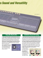
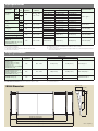
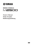
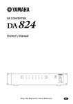
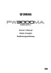
1
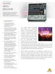
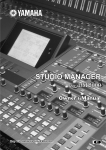
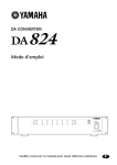
MIXING
CONSOLES
-24/-32/-40C/-48C/-56C
When discerning sound-reinforcement professionals think “console”
they also think “Yamaha.” And with good reason. Yamaha soundreinforcement consoles have, for many years, been standards by
which others are judged. Yamaha’s new M2500 consoles up the ante
once more, defining new levels of performance, control, versatility,
and reliability for an industry that never stands still. Innovate features such as the group/aux flip function and LCR panning offer
unprecedented control, while no-compromise circuit design, layout,
and component selection from the critical head amplifiers right
through to the output connectors ensure that you get the cleanest,
most accurate signal possible. The most important and in-demand
features have all been implemented as well: 4-band EQ with two
sweepable mid-bands on all mono inputs, a matrix submix of the
group, auxiliary, stereo and mono/center busses as well as the sub
inputs, 128-scene memory, 100-millimeter faders, and more.
■ A wide range of input configurations for all applications: 24, 32, 40, 48, or 56 mono inputs
with 4 stereo inputs.
■ A total of 25 output busses: 8 group, 14 auxiliary, 1 stereo, and 1 mono/center buss.
■ Full-length 100-mm faders for all group masters and aux sends 1 through 6 — the group master
faders/controls and aux send 7 through 14 controls can be flipped for maximum system versatility.
■ Group/auxiliary flip function allows the master section to be instantly optimized for main or
monitor mixing.
■ Mono channel pan controls switchable for LR or LCR operation.
■ All mono inputs feature switchable phantom power, 26-dB pad switches, 44-dB gain trim,
high-pass filter switches, and versatile 4-band EQ.
■ 128 mute scenes recallable via numeric keys, 8 direct recall switches, or MIDI control for mute
automation.
■ The 8 direct recall switches can alternatively be used as mute group switches.
■ 13 x 8 submix matrix mixes the group/aux, stereo, and mono busses, as well as the L and R sub
input signals, to 8 discrete outputs.
■ Odd/even group assign as well as stereo and mono buss assign switches on all input channels.
■ Aux sends 3 through 14 switchable for pre- or post-fader operation.
■ All outputs are balanced: stereo, mono/center, group, aux, monitor, and matrix out.
■ Insert patch points on all mono channels as well as the stereo, mono/center, group, and aux busses.
■ 11 large illuminated VU meters for precise visual level monitoring.
■ 3-point input level indicators on all input channels.
■ High-capacity, high-performance external power supply with full power monitoring (two can be
connected for automatic switchover in case of failure).
Photo: M2500-56C
All of the mono inputs and group master controls feature LCR
switches which, when engaged, assign the related panpot to the left,
right, and center busses for LCR panning rather than just to the left
and right busses as for standard LR stereo panning. When an LCR
switches is not engaged, the corresponding PAN control functions in
the normal way, panning the signal from left to right on the stereo
buss. When a channel’s LCR switch is engaged, however, the center
panpot position directly feeds the channel signal to the MONO/C
buss, which can feed a center amp/speaker system as required,
while intermediate pan positions feed both the L or R and C buss
proportionately. The advantage is that centered signals are heard
precisely in the center of the sound field, regardless of listening
position — an ideal situation for vocals, speech, etc.
(,while intermediate
pan positions feed both
● L R PAN
● LCR PAN
the L or R and C buss
proportionately.)
Intermediate pan pot
positions pan between
L
L
C
C
R
R
L&C when left of center
and C&R when posiMONO/C BUSS@@ STEREO BUSS L@@ STEREO BUSS R
tioned right of center.
Signal Level
This innovative feature makes it possible to flip the functions of
the group master 1 through 8 controls (including pan pots, assign
switches, and insert I/O jacks) with aux send controls 7 through 14
via a single switch. When the GROUP/AUX FLIP switch is set to
GROUP, the 100-mm group master faders and related controls
function in the normal way, affecting the signal fed to the console’s
group outputs — the ideal configuration for most house mixing
applications. When the GROUP/AUX FLIP switch is set to AUX,
however, the group master
faders are flipped with rotary aux
sends 7 through 14, so that all of
the console’s master aux sends
are controlled via full-length
faders for unmatched monitor
mixing convenience.
Switchable LR and LCR Panning
Signal Level
Group/Aux Flip Function
STEREO INPUTS
MONO INPUTS
INPUT CHANNELS
■ Inputs
■ 14 Aux Sends
The mono input channels feature balanced
XLR-type microphone/line inputs. +48V
Phantom power is independently switchable
for all mono inputs, providing direct compatibility with high-performance phantompowered condenser microphones and DI
boxes.
Stereo line sources can be directly connected to any of the 4 stereo input channels
(a total of eight inputs). Stereo channel 1 has
switchable “A” or “B” inputs: the “A” inputs are
balanced XLR type connectors, and the “B”
inputs are standard RCA pin jacks type for
compatibility with the widest possible range of
line sources. Stereo channels 2 through 4
have balanced TRS inputs.
The AUX 1 through AUX14 controls are
mono auxiliary sends, feeding the corresponding auxiliary busses. The AUX 7 through AUX
14 signals can be re-routed to the group
master controls, as described in the “MASTER
CONTROLS” section, below. AUX 1 and AUX 2
are hard-wired pre-fader, while the remaining
12 sends can be switched to receive the preor post-fader signal in groups of four.
■ Channel Insertion
Insert send/return patch points are
included on all mono channels for convenient
insertion of compressor/limiters (a must for
top-quality vocal sound), equalizers, or any
other outboard equipment you might need to
apply to individual channels.
■ Input Controls & Level Matching
Gain trim controls with a 44-dB range on
all mono inputs, independent 40-dB gain
controls for the A input on stereo channel 1
and stereo channels 2 through 4, and 30-dB
gain controls for the B input on stereo channel
1, facilitate optimum level matching with a
wide range of sources. The mono inputs
additionally feature 26-dB pad switches and
phase switches for easy input phase correction.
■ Filters & Flexible 4-band Channel
EQ
All mono channels feature a switchable
high-pass filters to effectively eliminate rumble
and other low-frequency noise. The mono
channels also feature a very flexible 4-band
equalizer which provides sweepable frequencies for the HI MID and LO MID bands. The
stereo channels offer 2-band shelving EQ. EQ
bypass switches are provided on all channels
so equalization can be punched in or out as
required without having to change settings.
■ Buss Assign & Pan/Balance
Controls
All mono and stereo channels have odd/
even assign switches for the 8 group busses,
as well as stereo and mono buss assign
switches. The mono channels have PAN
controls switchable for LR or LCR operation,
and the stereo channels have balance
controls.
■ 3-point Level Indicators
All mono and stereo channels feature 3point input level indicators for accurate
monitoring of pre-fader signal levels. SIGNAL,
NOM (nominal), and PEAK LEDs provide a
broader “view” of channel signal levels than
the usual one- or two-LED indicators.
■ Channel Faders, Pre-fader Listen,
& Channel ON Switches
Smooth, noise-free 100-mm linear faders
make it easy to set up the optimum balance
between channels, while PFL (Pre-Fader
Listen) switches allow convenient solo
monitoring of the channel’s pre-fader signal.
All channels additionally feature ON/EDIT
switches and indicators that can be used to
switch the channel signal into or out of the
mix — allowing editing of mute scenes, for
example — without changing any other
settings.
MASTER CONTROLS
■ Master Auxiliary Sends
■ Sub Inputs
Master auxiliary sends 1 through 6 feature
full-length 100-millimeter faders with ON and
AFL switches, and theses directly feed the
corresponding AUX outputs. Master auxiliary
sends 7 through 14 are normally rotary
controls with ON and AFL switches, feeding the
corresponding AUX outputs, but these can be
flipped with the 100-millimeter faders and
related controls normally assigned to the 8
group busses.
Sub inputs to the stereo L and R busses, the
mono/center buss, and the submix matrix
allow external line-level signals to be added to
the mix as required.
■ Group Master Controls
All 8 group master faders are full-length
100-mm types with ON/EDIT switches and
indicators, AFL switches, PAN controls, MATRIX
assign, STEREO assign, MONO assign, and LCR
panning mode switches. These group controls,
in conjunction with the flippable aux master
controls, lets you configure the console to
meet your group/auxiliary requirements while
retaining full use of all 25 output busses.
■ Group/Aux Flip Switch
Flips the functions of the master group
controls (1 through 8) with aux send masters
7 through 14. This makes it possible to to
instantaneously optimize the master control
section for main or monitor mixing applications.
■ All Balance Outputs with Insert
Patching
All outputs from the M2500 console —
stereo, mono/center, group, aux, monitor, and
matrix out — are electronically balanced for full
compatibility with professional equipment and
optimum performance with long signal runs.
The group/aux, aux, stereo, and mono outputs
also feature insert patch points for external
signal processing.
■ 128 MIDI Scene Memory & 8 Mute
Groups
In the M2500 console the channel, group/
aux, stereo, and mono/center buss mute
functions are electronically controlled by a
microcomputer and MIDI interface. Up to 128
mute “scenes” can be stored in memory and
recalled either via the panel controls or an
external MIDI device. Eight DIRECT RECALL
switches can be used for instant recall of the
most often-used scenes, while others can be
recalled via the numeric keys. The memory
contents can be checked and edited at any
time without actually affecting the mix.
In addition to recalling complete scenes,
external MIDI control can be used to individually turn the applicable channels and busses
off or on as required. A MIDI sequencer or
computer, for example, could be used for
complete mute automation. And since the
M2500 also transmits MIDI program change
messages whenever a scene is recalled, it can
be linked to MIDI-controllable signal processors so that appropriate effects are recalled
automatically. Furthermore, scene data can be
dumped to a MIDI data recorder or other
storage device for long-term storage.
■ Submix Matrix
The matrix mix concept was a Yamaha
innovation which has virtually become an
industry standard in professional audio
consoles. The M2500 features a 13 x 8 matrix
mix which allows the 8 group/aux buss signals,
the stereo signals, the mono buss signal, and
the L and R sub input signals to be mixed to
eight balanced outputs for extra stage monitor
mixes, zoned speaker mixes, or just about any
type of mix the job requires. All eight matrix
mixes include mix on/off switches and AFL
switches.
■ Flexible Monitoring & Metering
In addition to balanced stereo monitor
outputs, the M2500 consoles feature a
balanced mono/center monitor output for an
extra margin of monitoring versatility. There’s
also a separate headphone output with its own
level control. A L+R switch sums the left- and
right-channel signals when you want to
monitor in mono via the stereo monitor
outputs.
A total of 11 large illuminated VU meters
with built-in peak-reading LEDs provide
accurate visual level monitoring. Eight of the
meters can be switched to display levels on
the group busses, aux busses, or the matrix
outputs. The remaining three meters show
levels on the stereo and mono/center busses.
■ Oscillator/Talkback Module
For talkback the M2500 features a panelmounted microphone jack with level control
and on/off switch. For convenient system
calibration and testing there’s even a built in
oscillator with 100Hzm 1kHz, 10kHz and pink
noise output.
■ Lamp Connectors
Connectors for up to three Yamaha LA1800
(option) console lamps are provided on the
rear panel.
PW3000MA Power Supply
PW3000MA Specifications
A newly developed, high-performance PW3000MA power supply unit is available as an
optional accessory for the M2500 mixing console. Two PW3000MA units can be parallel
connected so that if one fails the other will automatically take over — with no need for
any extra automatic switchover equipment.
Power consumption
U.S. and Canadian model: 120V AC,60Hz / 500W 600 VA
European model:
230V AC, 50Hz/ 500W
Australian model:
240V AC, 50Hz/ 500W
Dimensions (H × D × W)
103.5 × 455 × 480 mm (4-1/16” × 17-5/16” × 18-7/8”)
Weight
15kg (33.1 Ibs)
Accessory
Connecting cable (1m) × 1
Rear Panel
M2500-24Front Panel
M2500-24 Rear Panel
M2500-40C Front Panel
M2500-40C Rear Panel
–60dB
–50dB
–40dB
–30dB
–20dB
–10dB
0dB
+10dB
+20dB
+30dB
(–26dB)
(0dB)
Pad:Off, Gain:Max
Pad:On, Gain:Max
Pad:Off, Gain:Min
Pad:On, Gain:Min
INPUT
1-24
1-32
1-40
1-48
1-56
ST CH 2-4
INPUT
R
L/MONO
R
INPUT B
L
R
INPUT A
L
GAIN
ST CH 1
26dB
PAD
80
ST CH 1A, 2-4
Gain:Max
ST CH 1B
Gain:Max
ST CH
Gain:Min
HPF
GAIN A
GAIN B
GAIN
B
A
Ø
LO
f
ON/EDIT
ON/EDIT
4 stage EQ
HI-MID
g
LO-MID
2 stage EQ
2 stage EQ
2 stage EQ
EQ
EQ
MIC
Clipping Level
MIC
INSERT I/O
from CPU
CHECK
ON
2 stage EQ
Control
HI
from CPU
CHECK
ON
f
Control
EQ
TB/OSC
PFL
AUX 11-14
Same as AUX 3-6
from CPU
ON
PRE
MONO
ST
AUX 7-10
Same as AUX 3-6
BAL
PFL
AUX 11-14
Same as AUX 3-6
ST CH 2-4
Same as ST CH 1
PEAK
NOM
SIGNAL
PRE
MONO
ST
AUX 7-10
Same as AUX 3-6
PAN
2
**
MIL
to MIR
MIO
AUX6
AUX5
AUX4
AUX3
AUX2
AUX1
MONO
**
*
GROUP
3 5 7
4 6 8
MIM
MIO
AUX6
AUX5
AUX4
AUX3
AUX2
MONO
to ST R
ST L
GROUP
AUX
3 5 7
1 3 5 7 9 11 13
4 6 8
2 4 6 8 10 12 14
AUX1
2
ST L
to ST R
1
to
LCR
1
AUX 8-14
from AUX 2-6
INSERT I/O
0dB
AUX 1
AUX
GROUP
from
GROUP 2-8
ON/EDIT
INSERT I/O
0dB
G1/A7
ON
AFL
AFL
MONO/C
ST R
ST L
MMAM
to MMPM
MMAO
*
**
AUX OUT
+4dB
1
GRP/AUX OUT
AUX/GRP OUT SUB IN ST
MONO
AUX OUT
SUB IN
+4dB
AUX 2-6
Same as AUX 1
ON
to METER
L
R
MONO
*
**
from INPUT
MMAM
to MMPM
MMAO
AUX/GRP OUT
+4dB
A7/G1
**
*
to MATRIX
LCR
GRP/AUX OUT
+4dB
G1/A7
MMAM
to MMPM
MMAO
MATRIX
MONO
ST
to METER
AFL
GRP/AUX G2/A8-G8/A14
and
AUX/GRP A8/G2-A14/G8
Same as
G1/A7
and
G7/A1
LEVEL
from CPU
GROUP/AUX FLIP
Control
CHECK
ON
PAN
to METER
LR
CHECK
ON
from CPU
from CPU
Control
INSERT I/O
0dB
MONO/C
ON/EDIT
CHECK
ON
Control
INSERT I/O
0dB
ST R
ON/EDIT
INSERT I/O
0dB
ST L
ON
AFL
PINK
G1/A7
G2/A8
**
*
SUB IN
+4dB
MATRIX
MMAM
to MMPM
MMAO
ST OUT
AFL
MATRIX
MATRIX
MATRIX
LR
MATRIX
METER
SELECT
G1-8/A7-14
AUX1-6
A7-14/G1-8
SUB IN MATRIX
R
L
+4dB
MONO/C
**
ST OUT
+4dB
R
MMAR
MMPR
to MONITOR
to
to MONITOR
*
**
ST OUT
+4dB
L
MMAL
to MMPL
MMAO
to MONITOR
G8/A14
G7/A13
from
OSCILATOR
ON
100Hz
1kHz
10kHz
LR
SUB IN
g
LO
LO
G1/A7
G2/A8
G3/A9
G4/A10
G5/A11
G6/A12
G7/A13
G8/A14
PEAK
NOM
SIGNAL
STEREO
MONO/C
INSERT I/O
0dB
UTILITY
SUB IN R
SUB IN L
MONO/C
ST R
ST L
G8/A14
G7/A13
G2/A8
G1/A7
u
q
CHECK
STORE
RECALL
from
LEVEL
ON
AFL
GRP/AUX, AUX/GRP
AUX, ST MONO
ST L
ST L
ST R
ST R
GRP/AUX, AUX/GRP
AUX, ST MONO
ST L, ST R
IN
OUT
THRU
Abbrev.
MIM
MIL
MIR
MIO
MMPM
MMPL
MMPR
MMAM
MMAL
MMAR
MMAO
MATRIX OUT
LR
LR
LR
INPUT
MASTER
PFL
MASTER
from
MONO/C
ST R
ST L
MONITOR bus
MONITOR INPUT MONO
MONITOR INPUT ST L
MONITOR INPUT ST R
MONITOR INPUT ON
MONITOR MASTER PFL MONO
MONITOR MASTER PFL ST L
MONITOR MASTER PFL ST R
MONITOR MASTER AFL MONO
MONITOR MASTER AFL ST L
MONITOR MASTER AFL ST R
MONITOR MASTER AFL ON
to TB
to Control
Mute
Control
OSC
CPU
*: MONITOR bus abbreviations
MATRIX OUT
+4dB
1-8
MIDI
MONITOR
MASTER
INPUT
(PFL)
PFL AFL
to METER
DIRECT
RECALL
8
7
2
1
MONO IN
ST IN L
ST IN R
MONO IN, ST IN
GRP/AUX, AUX/GRP
AUX, ST MONO
ENTER
0
9
2
1
MONO
ST
ON
PHANTOM +48V
MASTER
MONO
ST
MONO
ST
ON
HI
HI
L+R
PHONES
LEVEL
G8/A14
MATRIX 8
A14/G8
G7/A13
MATRIX 7
A13/G7
MATRIX 6
A12/G6
AUX 6
G6/A12
MATRIX 5
A11/G5
AUX 5
G5/A11
MATRIX 4
A10/G4
AUX 4
G4/A10
MATRIX 3
A9/G3
AUX 3
G3/A9
MATRIX 2
A8/G2
AUX 2
G2/A8
MATRIX 1
A7/G1
AUX 1
G1/A7
ON
Phones
MONITOR OUT
–60dB
–50dB
–40dB
–30dB
–20dB
–10dB
0dB
+10dB
+20dB
MONO/C
R
MONITOR
OUT
+4dB
L
BLOCK DIAGRAM
STEREO
MONO/C
Input specifications
Connection
PAD
0
CH INPUT
(1~n)*8
26
0
26
ST CH 1A INPUT
[L, R]
ST CH 1B INPUT
[L, R]
ST CH INPUT
[L, R] (2~4)
Gain
Trim
Actual Load
Impedance
−60
50–600 Ω Mics
&
600 Ω Lines
3 kΩ
−16
−30
+10
−20
+10
−30
+10
TALKBACK IN
MATRIX SUB IN [L, R]
5 kΩ
600 Ω Lines
10 kΩ
600 Ω Lines
5 kΩ
600 Ω Lines
10 kΩ
50–600 Ω Mics
10 kΩ
STREO [L, R], MONO/C SUB IN
600 Ω Lines
Sensitivity *9
Nominal
Connector In Mixer
Max before Clip
−80 dB (0.078 mV)
−60 dB (0.775 mV)
−54 dB (1.55 mV)
−34 dB (15.5 mV)
−40 dB (7.75 mV)
−14 dB (155 mV)
−36 dB (12.3 mV)
−16 dB (123 mV)
+4 dB (1.23 V)
−10 dB (245 mV)
+10 dB (2.45 V)
+30 dB (24.5 V)
−50 dB (2.45 mV)
−30 dB (24.5 mV)
−10 dB (245 mV)
−10 dB (245 mV)
+10 dB (2.45 V)
+30 dB (24.5 V)
−40 dB (7.75 mV)
−20 dB (77.5 mV)
0 dB (0.775 V)
−10 dB (245 mV)
+10 dB (2.45 V)
+30 dB (24.5 V)
XLR-3-31 type *2
RCA Pin Jack *3
−50 dB (2.45 mV)
−30 dB (24.5 mV)
−10 dB (245 mV)
−10 dB (245 mV)
+10 dB (2.45 V)
+30 dB (24.5 V)
−66 dB (0.388 mV)
−50 dB (2.45 mV)
−20 dB (77.5 mV)
XLR-3-31 type *5
+4 dB (1.23 V)
+24 dB (12.3 V)
Phono Jack (TRS) *6
0 dB (0.775 V)
+20 dB (7.75 V)
Phono Jack (TRS)*7
−2 dB (0.616 V)
−6 dB (388 mV)
Phono Jack (TRS)*4
−26 dB (38.8 mV)
CH INSERT IN (1~n) *8
STEREO [L, R], MONO/C
INSERT IN
GRP/AUX INSERT IN (1/7~8/14)
AUX INSERT IN (1~6)
*1
*2
*3
*4
*5
Input Level *1
For Use With
Nominal
10 kΩ
600 Ω Lines
−10 dB (245 mV)
In these specifications, when dB represents a specific voltage, 0dB is referenced to 0.775Vrms.
XLR connectors are balanced.
RCA Pin Jacks are unbalanced.
INPUT Phone Jacks (TRS) are balanced (T= HOT, R= COLD, S= GND).
XLR connector is unbalanced.
*6
*7
*8
*9
SUB IN Phone Jacks (TRS) are unbalanced (T= SIGNAL, R= GND, S= GND).
INSERT Phone Jacks (TRS) are unbalanced (T= OUTPUT, R= INPUT, S= GND).
n= 56, 48, 40, 32, or 24.
Sensitivity is the lowest level that will produce an output of +4dB (1.23V), or the nominal output level when the
unit is set to maximum level.
Output specifications
Actual Source
Impedance
STEREO OUT [L, R]
MONO/C OUT
GRP/AUX OUT (1/7~8/14)
AUX/GRP OUT (7/1~14/8)
AUX OUT (1~6)
MONITOR OUT [L, R, MONO/C]
MATRX OUT (1~8)
CH INSERT OUT (1~n)*5
STEREO INSERT OUT [L, R]
MONO/C INSERT OUT
GRP/AUX INSERT OUT (1/7~8/14)
AUX INSERT OUT (1~6)
PHONES OUT [L, R]
For Use With Nominal
Output Level *1
Nominal
Max before Clip
Connector In Mixer
150 Ω
600 Ω Lines
+4 dB (1.23 V)
+24 dB (12.3 V)
XLR-3-32 type *2
600 Ω
10 kΩ Lines
0 dB (0.775 V)
+20 dB (7.75 V)
Phone Jack (TRS) *3
8 Ω Phones
10 mW
20 mW
40 Ω Phones
30 mW
75 mW
100 Ω
*1 In these specifications, when dB represents a specific voltage, 0dB is referenced to 0.775 Vrms.
*2 All XLR connectors are balanced.
*3 INSERT Phone Jacks (TRS) are unbalanced (T= OUTPUT, R= INPUT, S= GND).
M2500 Dimensions
Stereo Phone Jack *4
*4 Stereo Phone Jack is unbalanced.
*5 n= 56, 48, 40, 32, or 24.
265 (10-7/16")
23 (7/8")
270 (10-5/8") 270 (10-5/8")
137
(5-3/8")
242 (9-1/2")
875 (34-7/16")
Connection
M2500-24: 1400 (55-1/8")
M2500-32: 1642 (64-5/8")
M2500-40C: 1899 (74-3/4")
M2500-48C: 2142 (84-5/16")
M2500-56C: 2385 (93-7/8")
Unit : mm(inch)
General specifications
Total Harmonic Distortion
(Master output)
Less than 0.1% (THD + N)
20 Hz–20 kHz @ +14 dB 600 Ω
Frequency Response
(Master Output)
0 + 1, –3 dB
20 Hz–20 kHz @ +4 dB 600 Ω
(Input Gain control at Minimum)
Hum & Noise
*1
−128 dB
−99 dB
−64 dB (68 dB S/N)
−80 dB (84 dB S/N)
−81 dB (85 dB S/N)
−75 dB (79 dB S/N)
−90 dB (94 dB S/N)
Crosstalk
−70 dB
−70 dB
−50 dB
Rs = 150 Ω (20 Hz–20 kHz)
Input sensitivity=-60 dB
Equivalent Input Noise.
Residual Output Noise. (STEREO OUT,
MONO/C OUT, GROUP/AUX OUT, AUX OUT,
AUX/GROUP OUT)
STEREO OUT Master Level control and one
Ch fader at nominal level.
STEREO OUT, MONO/C OUT Master fader at
nominal level and all Ch assign SW’s off and all
GROUP to ST SW’s off.
GROUP 1/AUX 7~GROUP 8/AUX 14 OUT
Master Level control at nominal level and all Ch
assign SW’s off.
GROUP/AUX FLIP SW off.
AUX 1~6, AUX 7/GROUP 1~AUX 14/GROUP
8 OUT Master Level control at nominal level
and all Ch send controls at minimum.
GROUP/AUX FLIP SW off.
MATRIX OUT Master level control at nominal
level and all Matrix Mix controls at minimum
level.
@ 1 kHz adjacent inputs.
@ 1 kHz input to output. (CH INPUT)
@ 1 kHz input to output. (ST CH INPUT)
Maximum Voltage Gain
*GROUP/AUX FLIP SW = off
60 dB
CH INPUT to CH INSERT OUT
84 dB
CH INPUT to GROUP 1/AUX 7~GROUP 8/
AUX 14 OUT
80 dB
CH INPUT to AUX 1, 2 OUT (Pre Fader)
90 dB
CH INPUT to AUX 3~6, AUX 7/GROUP 1~
AUX 14/GROUP 8 OUT (Post Fader)
84 dB
CH INPUT to STEREO OUT (CH to ST)
70 dB
CH INPUT to MONITOR OUT (PFL)
CH INPUT PAD SW
26 dB
CH INPUT GAIN control
44 dB
variable
ST CH 1A, 2–4 INPUT GAIN control
40 dB
variable
ST CH 1B INPUT GAIN control 30 dB
variable
CH INPUT High Pass Filter
CH INPUT Equalization
+15, −15 dB maximum
HIGH
HIGH-MID
LOW-MID
LOW
ST CH INPUT Equalization
+15, −15 dB maximum
HIGH
LOW
Phantom Power
+48VDC is applied to balanced inputs (via 6.8 kΩ current-limiting/isolation
resistors) for powering condenser microphones ; may be turned ON or
OFF via rear-panel phantom Master switch.
When Master is ON, individual channels may be turned ON or OFF via
+48V switches (with red LED) on each input channel.
CH LED Indicators
PEAK
NOM
SIGNAL
ST CH LED Indicators
PEAK
NOM
SIGNAL
LED (red) built into each ST CH INPUT turns
on when pre-fader [L+R] level reaches +17 dB.
LED (yellow) built into each ST CH INPUT turns
on when pre-fader [L+R] level reaches 0 dB.
LED (green) built into each ST CH INPUT turns
on when pre-fader [L+R] level reaches −13 dB.
Oscillator/Noise
Switchable sine wave @ 100 Hz, 1 kHz or 10 kHz, or pink noise.
Scene Memory
Direct Scene Memory recall switches (1–8)
Switchable Scene Memory recall (1–128)
VU Meters
11 illuminated meters
(0VU= +4 dB output @ 600 Ω load)
#1 ; GROUP 1/AUX 7, AUX 1, AUX 7/GROUP 1, MATRIX 1
#2 ; GROUP 2/AUX 8, AUX 2, AUX 8/GROUP 2, MATRIX 2
#3 ; GROUP 3/AUX 9, AUX 3, AUX 9/GROUP 3, MATRIX 3
#4 ; GROUP 4/AUX 10, AUX 4, AUX 10/GROUP 4, MATRIX 4
#5 ; GROUP 5/AUX 11, AUX 5, AUX 11/GROUP 5, MATRIX 5
#6 ; GROUP 6/AUX 12, AUX 6, AUX 12/GROUP 6, MATRIX 6
#7 ; GROUP 7/AUX 13, NONE, AUX 13/GROUP 7, MATRIX 7
#8 ; GROUP 8/AUX 14, NONE, AUX 14/GROUP 8, MATRIX 8
#9 ; STEREO L, PFL/AFL L
#10; MONO/C
#11; STEREO R, PFL/AFL R
VU Meter Peak Indicators
LED (red) built into each VU meter turns on when output signal is above
the level 3 dB lower than clipping level.
Dimension
Height
Depth
Width
18 dB/octave roll-off below 80 Hz at −3 dB
point.
Weight
10 kHz (shelving)
400–8 kHz (peaking)
80–1.6 kHz (peaking)
100 Hz (shelving)
LED (red) built into each CH INPUT turns on
when pre-fader level reaches +17 dB.
LED (yellow) built into each CH INPUT turns
on when pre-fader level reaches 0 dB.
LED (green) built into each CH INPUT turns on
when pre-fader level reaches −13 dB.
265 mm (10-6/7”)
875 mm (34-3/8”) Except rear connectors
56C: 2385 mm (93-7/8")
48C: 2142 mm (84-5/16")
40C: 1899 mm (74-3/4")
32: 1642 mm (64-5/8")
24: 1400 mm (55-1/8")
56C: 102 kg (224.9 Ibs.)
48C: 93 kg (205 Ibs.)
40C: 84 kg (185.2 Ibs.)
32: 71 kg (156.5 Ibs.)
24: 62 kg (136.7 Ibs.)
Accessory
Connecting cable (3 m) × 1
10 kHz (shelving)
100 Hz (shelving)
● 0 dB is referenced to 0.775 Vrms.
*1 Hum & Noise are measured with a 6 dB/octave filter @ 12.7 kHz; equivalent to
a 20 kHz filter with infinite dB/octave attenuation.
YAMAHA Web Site
http://www.yamaha.co.jp/english
http://www.yamaha.co.jp/product/proaudio/homeenglish/
All specifications subject to change without notice.
This document is printed on chlorine free (ECF) paper.
For details please contact:
LPA436 991223
Printed in Japan