1
January 1999
600P86176
Xerox Laser Printing Systems
Tape formats
manual
Prepared by:
Xerox Corporation
701 S. Aviation Boulevard
El Segundo, CA 90245
USA
©1999 by Xerox Corporation. All rights reserved.
Copyright protection claimed includes all forms and matters of copyrightable material and information
now allowed by statutory judicial law or hereinafter granted, including without limitation, material generated
from the software programs displayed on the screen such as icons, screen displays, or looks.
Printed in the United States of America.
XEROX® and all Xerox product names mentioned in this publication are trademarks of XEROX CORPORATION.
Other company trademarks are also acknowledged.
Changes are periodically made to this document. Changes, technical inaccuracies, and typographic
errors will be corrected in subsequent editions.
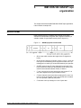
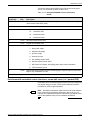
Notice
This manual describes the characteristics of various tape formats
which can be processed by Xerox laser printing systems Operating
System Software (OSS). Printer carriage control conventions are
also included. The information is organized into chapters by vendor.
Laser safety
WARNING: Use of controls or adjustments, or performances other
than specified herein, may result in hazardous radiation exposure.
Xerox laser printing systems are certified to comply with laser
performance standards set by the U.S. Department of Health,
Education, and Welfare as Class 1 laser products. This is a class of
laser products that does not emit hazardous radiation. This is
possible only because the laser beam is totally enclosed during all
modes of customer operation.
When performing operator functions, laser warning labels may be
visible. These labels are to alert and remind the service
representative and are placed on or near panels or shields which
require a tool for removal. THE PANELS TO WHICH THESE
LABELS ARE FIXED OR NEAR ARE NOT TO BE REMOVED BY
ANYONE OTHER THAN A XEROX SERVICE REPRESENTATIVE.
This label is located inside the left door, on the machine frame just
above the directions for clearing a jam in area 4.
XEROX LASER PRINTING SYSTEMS TAPE FORMATS MANUAL
iii
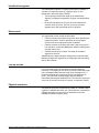
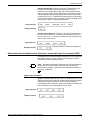
Operation safety
Your Xerox equipment and supplies have been designed and tested
to meet strict safety requirements. These include safety agency
examination and approval, and compliance with established
environmental standards. Attention to the following notes will ensure
the continued safe operation of your equipment.
Always connect equipment to a properly grounded power source
receptacle. If in doubt, have the receptacle checked by a qualified
electrician.
!
Warning: WARNING: Improper connection of the equipment
grounding conductor can result in electrical shock.
!
Always place equipment on a solid support surface with adequate
strength for the weight of the machine.
Always use materials and supplies specifically designed for your
Xerox equipment. Use of unsuitable materials may result in poor
performance and can possibly create a hazardous situation.
Never move or relocate either the printer or the system controller
without first contacting Xerox for approval.
Never use a ground adapter plug to connect equipment to a power
source receptacle that lacks a ground connection terminal.
Never attempt any maintenance function that is not specifically
described in your operator guide.
Never remove any covers or guards that are fastened with screws.
There are no operator-serviceable areas within these covers.
Never override or “cheat” electrical or mechanical interlock devices.
Never use supplies or cleaning materials for other than their intended
purposes. Keep all materials out of the reach of children.
Never operate the equipment if unusual noises or odors are noticed.
Disconnect the power cord from the power source receptacle and call
Xerox service to correct the problem.
If you need any additional safety information concerning the
equipment or materials Xerox supplies, call Xerox Product Safety at
the following toll-free number:
1-800-828-6571
iv
XEROX LASER PRINTING SYSTEMS TAPE FORMATS MANUAL
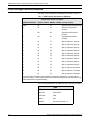
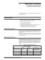
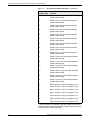
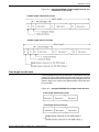
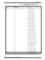
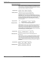
Related publications
A number of related documents are listed below for your
convenience. For a complete list and description of available Xerox
documentation, please refer to the Xerox Documentation Catalog
(Publication 610P17517) or call the Xerox Document Subscription
Service (XDSS) at 1-800-445-5554.
Publication
Number
Xerox Laser Printing Systems
Message Guide—Version 3
720P10661
Xerox 4850 HighLight Color
Laser Printing System
Reference Set
720S90680
Xerox 4850 HighLight Color
Laser Printing System
Product Guide
720P86211
Xerox 4850 HighLight Color
Laser Printing System
Applications Guide
720P86231
Xerox 4850 HighLight Color
Laser Printing System
System Guide
720P86241
Xerox 4850 HighLight Color
Laser Printing System
System Operator Guide
720P86160
Xerox 4850 HighLight Color
Laser Printing System
Operations Reference
720P87140
Xerox 4850 HighLight Color
Laser Printing System
PDL/DJDE Reference
720P87161
Xerox 4850 HighLight Color
Laser Printing System
Operator Command Summary
720P85990
Xerox 4135 Laser Printing
System Product Guide
720P85931
Xerox 4135 Laser Printing
System Operator Guide
720P85961
Xerox 4135 Laser Printing System
PC User Interface Reference
720P86751
Xerox 4135 Laser Printing
System Operations Reference
720P87151
Xerox 4135 Laser Printing
System PDL/DJDE Reference
720P87171
Xerox Laser Printing Systems
Forms Creation Guide
720P90081
Xerox Laser Printing Systems
System Generation Guide
720P90061
XEROX LASER PRINTING SYSTEMS TAPE FORMATS MANUAL
v
Xerox Laser Printing Systems
Standard Font Library
Font User Guide
600P86175
*Contact the Xerox Document Subscription Service (XDSS) at 1-800445-5554 for special ordering instructions.
* *Order directly from the Xerox Systems Institute at 1-408-737-4652.
vi
XEROX LASER PRINTING SYSTEMS TAPE FORMATS MANUAL
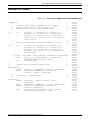
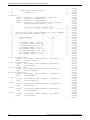
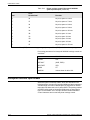
Table of Contents
1.
2.
Notice
iii
Laser safety
iii
Operation safety
iv
Related publications
v
American National Standards Institute (ANSI) labeled tapes
Tape marks
1-1
Labels
1-1
ANSI labeled tape structures
1-2
VOL1 label
1-7
HDR1, EOV1, EOF1 labels
1-8
HDR2, EOV2, EOF2 labels
1-10
HDR3-9, EOV3-9, EOF3-9 labels
1-11
UVL, UHL, UTL labels
1-11
Block sequence indicator
1-11
Printer carriage control conventions
1-12
ANSI tape JSL sample
1-13
IBM OS/360 and DOS/360 standard labeled tapes
IBM labeled tapes
3.
1-1
2-1
2-1
OS/360 ANSI labeled tapes
2-1
IBM standard labeled tapes
2-1
VOL1 label
2-5
VOL2 through VOL8 labels
2-5
HDR1, EOV1, EOF1 labels
2-6
HDR2, EOV2, EOF2 labels
2-7
UHL1-8, UTL1-8 labels
2-9
Printer carriage control conventions
2-9
IBM OS and DOS tape JSL sample
2-11
IBM DOS/360 GRASP tape organization
Record format
3-1
3-1
Identification segment
3-2
Data records
3-2
Line-up records
3-2
Physical record size
3-2
Sample data block
3-3
GRASP carriage control conventions
XEROX LASER PRINTING SYSTEMS TAPE FORMATS MANUAL
3-3
vii
TABLE OF CONTENTS
4.
5.
6.
GRASP interspersed block tapes
3-4
POWER and GRASP tapes
3-5
IBM DOS/360 POWER II tape organization
Tape formats
4-1
Block version characteristics (4.0, 4.1, 4.2)
4-1
Version 4.1
4-2
Version 4.2
4-2
Tape format examples
4-3
POWER and GRASP tape JSL sample
4-4
IBM POWER/VS and POWER/VSE tape organization
5-1
Tape formats
5-1
File formats
5-1
Data formats
5-2
POWER and GRASP tape JSL sample
5-5
UNIVAC Series 70 (US70) magnetic tape organization
6-1
Labeled tapes
6-1
Label groups and sets
6-1
Header label group
6-1
Header label sets
6-2
Volume label
6-2
File header label
6-2
User header label
6-4
Trailer labels
6-4
Trailer label sets
6-5
File trailer labels
6-5
User trailer label
6-6
Tape configurations
6-6
Unlabeled tapes
Tape marks
6-7
6-8
Labeled tapes
6-8
Unlabeled tapes
6-8
Data formats
6-9
US70 labeled and unlabeled tape formats
6-9
Alternate device tapes
6-9
Tape organization
Carriage control byte
COBOL print tapes
viii
4-1
6-9
6-10
6-10
Format 1
6-10
Format 2
6-11
XEROX LASER PRINTING SYSTEMS TAPE FORMATS MANUAL
TABLE OF CONTENTS
Format 3
6-11
Format 4
6-11
US70 printer control conventions
Printer control byte
7.
9.
6-13
UNIVAC tape JSL sample
6-14
Xerox ANSI standard labeled tapes and unlabeled tapes
7-1
7-1
Control Program-Five (CP-V) and ANSI labeled tapes
7-1
Unlabeled tapes
7-1
Nonstandard labels
7-2
Carriage control conventions
7-3
Xerox tape JSL sample
7-6
Medium Burroughs system tapes
8-1
Record format
8-1
Label types
8-2
Tape configurations
8-3
Carriage control conventions
8-3
Burroughs tape JSL sample
8-5
Large Burroughs system tapes
Burroughs labeled tapes
9-1
9-1
Record format
9-1
Line-up records
9-2
Carriage control
9-3
Character set
9-4
Burroughs tape JSL sample
10.
6-12
Printer carriage control tape
Xerox labeled tapes
8.
6-11
Honeywell tapes
9-4
10-1
4 x 3 packed 6-bit character format
10-1
Honeywell 200/2000 tape formats
10-3
Honeywell 200/2000 data formats
10-8
Bannered data format
10-8
Variable length record format
10-8
Fixed length record format
10-9
System print tape data format
10-10
Honeywell 200/2000 carriage control
10-10
Honeywell 600/6000 tape formats
10-12
Honeywell 600/6000 data formats
10-16
Variable length record format, Honeywell 6000 standard system tapes
10-16
XEROX LASER PRINTING SYSTEMS TAPE FORMATS MANUAL
ix
TABLE OF CONTENTS
Data format with embedded control characters, normal edit mode (4
x 3 packed BCD)
10-17
Single control characters
10-18
Paired control characters
10-18
Data format with embedded control characters, normal edit mode (9
x 8 packed ASCII)
10-19
11.
Single control characters
10-19
Paired control characters
10-20
Carriage control (Honeywell 600/6000)
10-21
Honeywell 2000 and 6000 tape JSL samples
10-23
Univac SDF tape format
11-1
Univac ASCII character set
11-1
Control records
11-4
Print image control record
12.
Heading string “H”
11-8
Setup string “S”
11-9
Margin string “M”
11-9
Line string “L”
11-9
Data records
11-10
Appropriate JSL coding for Univac tapes
11-11
IBM OS Writer tape organization
12-1
OS Writer report tape format
12-1
Job Descriptor Library (JDL) specification
12-2
Sample report creation under an OS Writer
12-2
Procedure
12-3
Steps to creating an OS Writer tape
WRITER tape JSL sample
13.
NCR tapes
13-1
13-1
Printer control block codes
15.
x
12-4
12-5
Carriage control conventions
14.
11-8
13-2
Function code (F)
13-2
Graphics code (G)
13-3
Selective print character (P)
13-3
Space code (S)
13-3
Undefined tapes
14-1
File format
14-1
Data format
14-2
Undefined tape JSL sample
14-3
DEC PDP-11 tapes
15-1
XEROX LASER PRINTING SYSTEMS TAPE FORMATS MANUAL
TABLE OF CONTENTS
Tape formats
15-1
File formats
15-1
ANSI labeled tapes
Data formats
15-3
Data structure characteristics
15-3
Operating system operations
15-4
FONTINDEX
15-4
Control codes
15-4
Points to note
15-5
PDP-11 (RSX) tape JSL sample
16.
15-3
ICL 2900 VME/B tape format
15-7
16-1
Tape formats
16-1
Data block formats
16-1
Carriage control conventions
16-2
Normal format effectors
16-3
Embedded format effectors
16-4
ICL tape JSL sample
16-5
Glossary
Index
XEROX LASER PRINTING SYSTEMS TAPE FORMATS MANUAL
GLOSSARY-1
INDEX-1
xi
TABLE OF CONTENTS
xii
XEROX LASER PRINTING SYSTEMS TAPE FORMATS MANUAL
1.
1American National Standards
Institute (ANSI) labeled tapes
The American National Standards Institute has defined standard
labeled magnetic tapes in ANSI Standard X3.27—1969. The
structure of these tapes is described in the following sections on tape
marks and labels.
Tape marks
The tape mark is used on ANSI tapes in the following places:
•
•
Following every file header label group
•
Preceding and following the end-of-volume label group (a
double tape mark follows the last volume).
Preceding and following the end-of-life label group (a double
tape mark follows the last, or only, file on tape)
Used in the manner described above, the tape mark identifies the
boundaries between the data and label groups of a file, and the label
groups in consecutive files.
Double tape mark
A double tape mark (two consecutive tape marks) indicates that no
further data follows on the tape. A double tape mark also occurs
between a header label group and a trailer label group when a file
containing no information (a null file) is written. This null file double
tape mark is formed by the tape mark following the file header label
group and the one preceding the end-of-file label group.
Labels
There are two general classes of labels for ANSI tapes: operating
system labels and user labels. Operating system labels are
generated and processed by the operating system. User labels are
generated and processed by user programs.
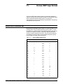
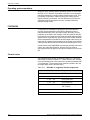
Four types of labels
Within these general classes, there are four types of labels, each 80
characters long. They are beginning-of-volume, beginning-of-file,
end-of-volume, and end-of-file. The names of the various classes
and types of labels are defined in table 1-1.
Note: In user labels, the letter ’a’ refers to any of the graphic
characters defined in ANSI Standard X3.4-1968.
XEROX LASER PRINTING SYSTEMS TAPE FORMATS MANUAL
1-1
AMERICAN NATIONAL STANDARDS INSTITUTE (ANSI) LABELED TAPES
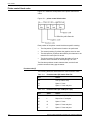
Table 1-1.ANSI labels
Type
Operating system labels
User labels
Beginning-of-volume
VOL1 (required (Additional VOL labels
prohibited)
UVL1 to UVL9 (optional)
Beginning-of-file
HDR1 (required) HDR2 to HDR9
(optional)
UHLa (optional; unlimited number
allowed)
End-of-volume
EOV1 (required) EVO2 to EOV9
(optional)
UTLa (optional; unlimited number
allowed)
End-of-file
EOF1 (required) EOF2 to EOF9
(optional)
UTLa (optional; unlimited number
allowed)
The beginning-of-volume label identifies the volume and its owner
and is often referred to as a volume label. Other labels are called “file
labels” and are either header labels (if they precede the file) or trailer
labels (if they follow the file).
The Xerox/OSS can process four tape configurations:
•
•
•
•
Single file, single volume
Single file, multiple volume
Multiple file, single volume
Multiple file, multiple volume.
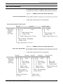
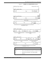
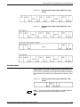
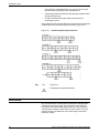
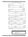
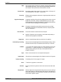
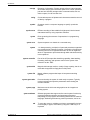
ANSI labeled tape structures
The locations of the types and classes of labels in these
configurations are shown in figures 1-1, 1-2, and 1-3. Figure 1-1
shows ANSI labeled tape structure when no optional labels are used.
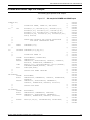
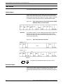
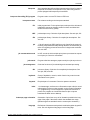
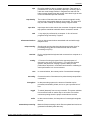
Figure 1-2 shows ANSI labeled tape structures with end-of-file (EOF)
and end-of-volume (EOV) marks coinciding.
1-2
•
In general, the pattern shown in option 1, figure 1-2, occurs
when the end-of-tape reflective strip is reached while writing the
last block of a file. Usually, the operating system does not yet
know that this is the last block, and the EOV label group is
recorded at this time.
•
On the other hand, the pattern shown in option 2, figure 1-2,
occurs when the reflective strip is reached after the EOF label
group has been started.
•
The pattern shown in option 3, figure 1-2, permits the initiation
of any file within a file set at the beginning of a volume. When
this configuration is used, the block count (field 12) of the endof-volume label is undefined. File sets are not terminated by an
end-of-volume label group.
XEROX LASER PRINTING SYSTEMS TAPE FORMATS MANUAL
AMERICAN NATIONAL STANDARDS INSTITUTE (ANSI) LABELED TAPES
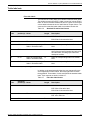
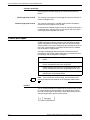
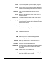
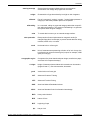
Structures with optional labels
Figure 1-3 shows ANSI labeled tape structure when optional labels
are used. Optional operating system and user labels are used to
structure files, as follows, without otherwise modifying the
relationship between the required labels and files.
•
Optional operating system labels of a given type follow a
required label of the same type.
•
User labels of a given type directly follow a consecutive group of
operating system labels of the same type. When no optional
operating system labels are used in the label group, the user
labels directly follow a required label of the same type.
•
•
There are no tape marks within a group of labels.
Every label is completed on the volume where the first label of a
group was reached.
XEROX LASER PRINTING SYSTEMS TAPE FORMATS MANUAL
1-3
AMERICAN NATIONAL STANDARDS INSTITUTE (ANSI) LABELED TAPES
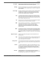
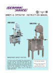
Figure 1-1.
1-4
ANSI labeled tape structure
XEROX LASER PRINTING SYSTEMS TAPE FORMATS MANUAL
AMERICAN NATIONAL STANDARDS INSTITUTE (ANSI) LABELED TAPES
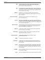
Figure 1-2.
*
ANSI labeled tape structure-assuming coincident
end-of-life and end-of-volume where a continuation
volume exists
If end-of-volume and end-of-file coincide, the labeling configuration is
as shown above. The letters (A) and (B) indicate to which file the
labels belong. These tapes assume no optional operating system or
user labels are used
XEROX LASER PRINTING SYSTEMS TAPE FORMATS MANUAL
1-5
AMERICAN NATIONAL STANDARDS INSTITUTE (ANSI) LABELED TAPES
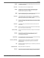
Figure 1-3.
*
ANSI label groups with optional labels
For the first file on a volume, HDR1 immediately follows the last
volume label without an intervening tape mark.
Note:
1. The letter “a” refers to any of the graphic characters defined in
the ANSI Standard X3.4—1968.
2. The letter “n” refers to a number 2 through 9.
1-6
XEROX LASER PRINTING SYSTEMS TAPE FORMATS MANUAL
AMERICAN NATIONAL STANDARDS INSTITUTE (ANSI) LABELED TAPES
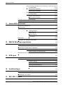
VOL1 label
The VOL1 label must appear as the first block on every ANSI labeled
tape and in no other position. It provides the identification for a
particular reel of tape. No other label is permitted whose identifier
(first three characters) is VOL. The VOL1 label is described in table
1-2.
Table 1-2.VOL1 label (ANSI tapes)
Name
Character
position(s)
Field
Description
Label identifier
1-3
1
This is the 3-character identifier VOL.
Label number
4
2
This is the number 1.
Volume serial —number
5-10
3
This is a 6-character code assigned by the owner to
identify this reel (physical volume) of tape. These
characters must be those defined in ANSI Standard
X3.27—1969 as “a” characters.
Accessibility
11
4
This is an access code. Any of the characters
specified for the volume serial number may be used.
A space means unlimited access; any other character
means special handling.
Reserved
12-31
5
Spaces.
Reserved
32-37
Owner identification
38-51
8
This is an owner identification code composed of
characters defined in ANSI Standard X3.27—1969 as
“a” characters.
Reserved
52-79
8
Spaces.
Label standard level
80
9
This is a standard level code. A number 1 indicates
that the labels and data formats on this volume
conform to ANSI Standard X3.27—1969. A space
indicates that they do not.
Spaces.
XEROX LASER PRINTING SYSTEMS TAPE FORMATS MANUAL
1-7
AMERICAN NATIONAL STANDARDS INSTITUTE (ANSI) LABELED TAPES
HDR1, EOV1, EOF1 labels
Note: The formats and contents of these labels are identical except
for the block count. The formats are shown in table 1-3.
Table 1-3.HDR1, EOV1, and EOF1 labels (ANSI) tapes
Name
Character
position(s)
Field
Description
Label identifier
1-3
1
This is the 3-character identifier HDR, EOV, or EOF.
Label number
4
2
This is the number 1.
File identifier
5-21
3
This may be made up of any of the characters defined
in the ANSI Standard X3.27—1969 as “a” characters.
Set identification
22-27
4
This identifies the set of files to which this belongs and
may be any of the characters defined in the ANSI
Standard X3.27—1969 as “a” characters. The
identification is the same for all files of a multi-file set.
File section number*
28-31
5
This number is 0001 for the first header label of each
file. This applies to the first or only file on a volume
and to subsequent files on a multi-file volume. The
field is incremented by 1 on each subsequent volume
of the file.
File sequence number
32-35
6
This is a 4-digit numeric field that specifies the
sequence number of files within the volume or set of
volumes. Within all the labels for a given file, this field
contains the same number.
Generation number (optional) 36-39
7
This is a 4-digit numeric field that specifies the
sequence number of files within the volume or set of
volumes. Within all the labels for a given file, this field
contains the same number.
Generation version (optional)
40-41
8
This is a 2-digit numeric field that specifies successive
iterations of the same generation. The generation
version number of the first attempt to produce a file is
00.
Creation date
42-47
9
This consists of a space, followed by two numeric
digits for the year, followed by three numeric digits for
the day (001 to 365) within the year.
Expiration date
48-53
10
This field has the same format as field nine. An
“expired” file is one in which today's date is equal to,
or later than, the date given in this field. If this
condition is satisfied, the remainder of this volume
may be overwritten. To be effective on multi-file
volumes, the expiration date of a file must be less
than or equal to the previous “expire from” date of all
previous files on the volume.
* Fields 3, 5, and 12 are used by the operating system.
1-8
XEROX LASER PRINTING SYSTEMS TAPE FORMATS MANUAL
AMERICAN NATIONAL STANDARDS INSTITUTE (ANSI) LABELED TAPES
Table 1-3.HDR1, EOV1, and EOF1 labels (ANSI) tapes (continued)
Name
Character
position(s)
Field
Description
Accessibility
54
11
This indicates any restriction on who may have
access to information in this file and may be any one
of the characters defined in the ANSI Standard
X3.27—1969 as “a” characters. A space indicates
unlimited access; any other character indicates
special handling.
Block count*
55-60
12
For HDR1, this field contains zeros. For EOV1 and
EOF1, it is a 6-digit numeric field specifying the
number of data blocks (exclusive of labels and tape
marks) since the preceding HDR group.
System code (optional)
61-73
13
This is a 13-character field specifying the operating
system that recorded this file. Any of the characters
defined in ANSI Standard X3.27—1969 as “a”
characters may be used
Reserved
74-80
14
Spaces
* Fields 3, 5, and 12 are used by the operating system.
The HDR1 label is required for all files and for continuation of files on
succeeding reels. It identifies the file and contains operating system
information that relates to the file.
The EOV1 label is required following the last data block on a tape
when the file or file set is continued on a succeeding tape. It is
separated from the last data block by the tape mark that must
precede every end-of-volume label group.
The EOF1 label is required following the last data block of every file.
It is separated from the last data block by the tape mark that must
precede every end-of-file group.
XEROX LASER PRINTING SYSTEMS TAPE FORMATS MANUAL
1-9
AMERICAN NATIONAL STANDARDS INSTITUTE (ANSI) LABELED TAPES
HDR2, EOV2, EOF2 labels
These labels are optional. EOF2 and EOV2 may be formatted
differently by different operating systems.
The HDR2 label is optional but is provided automatically by some
operating systems. When used, it must directly follow HDR1. HDR2
generally provides data relating to the physical parameters of the
recorded file, including record format, record length, and block
length. Table 1-4 describes the format of HDR2 labels.
Table 1-4.HDR2, EOV2, and EOF2 labels (ANSI tapes)
Name
Character
position(s)
Field
Description
Label identifier
1-3
1
This is the 3-character identifier HDR, EOV, or EOF.
Label number
4
2
This is the number 2.
Record format*
5
3
F = fixed length.
D = variable length with the number of characters in
the record specified in decimal.
U = undefined length.
Block length*
6-10
4
This specifies the maximum number of characters per
block and is a 5-digit numeric field.
For Burroughs large systems ANSI format, this field
represents Burroughs' words (6 characters per word)
rather than a character count.
Record length*
11-15
5
This specifies record length if record format is F,
maximum record length including any count fields if
record format is D or V, or undefined if record format
is undefined. Record length is a 5-digit numeric field.
Reserved for operating
systems
16-49
6
This field may have any of the characters defined in
the ANSI Standard X3.27—1969 as “a” characters.
Block attribute*
50
7
In the HDR2 label for IBM labels only, this field is the
block attribute.
Buffer offset*
51-52
8
This is a 2-digit numeric field specifying the character
length of any additional field inserted before a data
block (e.g., block length). This length is included in
block length (field 4).
Reserved
53-80
9
Spaces
(IBM only)
* Fields 3, 4, 5, 7, and 8 are used by the operating system.
The EOV2 label is optional and is provided automatically by some
operating systems. When used, it must directly follow EOV1. In some
operating systems, EOV2 is identical to HDR2. Table 1-4 describes
the format of these labels. In other operating systems, EOV2 has the
format described in table 1-5. (Refer to next section.)
The EOF2 label is optional but is provided automatically by some
operating systems. When used, it must follow EOF1 directly. In some
operating systems, EOF2 is identical to HDR2. Table 1-4 describes
the format of these labels. In other operating systems, EOF2 has the
format described in table 1-5. (Refer to next section.)
1-10
XEROX LASER PRINTING SYSTEMS TAPE FORMATS MANUAL
AMERICAN NATIONAL STANDARDS INSTITUTE (ANSI) LABELED TAPES
HDR3-9, EOV3-9, EOF3-9 labels
These operating system labels are optional. The formats of the labels
are shown in table 1-5.
Table 1-5.HDR3-9, EOV3-9, EOF3-9 labels
Name
Character
position(s)
Field
Description
Label identifier
1-3
1
This is the 3-character identifier HDR, EOV, or EOF.
Label number
4
2
This is a 1-digit number from 3 to 9.
Operating system option
5-80
3
This field may have any of the characters defined as
“a” characters in ANSI Standard X3.37—1969.
*In some operating systems, EOF2 and EOV2 may use this format.
UVL, UHL, UTL labels
These are optional user labels. Their format is described in table 1-6.
Table 1-6.UVL, UHL, and UTL labels (ANSI tapes)
Name
Character
position(s)
Field
Description
Label identifier
1-3
1
This is the 3-character identifier UVL, UHL, or UTL.
Label name
4
2
For UVL, this may be a number from 1 to 9. For UHL
and UTL, this may be any of the characters defined in
ANSI Standard X3.27-1969 as “a” characters.
User option
5-80
3
This may be any character defined in ANSI Standard
X3.27-1969 as “a” characters.
Block sequence indicator
Tapes recorded with the optional block sequence indicator referred
to by the appendix of the ANSI Standard X3.27—1969 cannot be
printed.
XEROX LASER PRINTING SYSTEMS TAPE FORMATS MANUAL
1-11
AMERICAN NATIONAL STANDARDS INSTITUTE (ANSI) LABELED TAPES
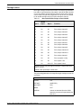
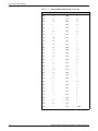
Printer carriage control conventions
The ANSI control characters for IBM tapes are shown in table 1-7.
Table 1-7.ANSI control characters for IBM tapes
Hexadecimal control characters
USASCII GRAPHIC
USASCII TAPES EBCDIC TAPES Control function
blank
20
40
Space one line before printing.
0
30
F0
Space two lines before
printing.
-
2D
60
Space three lines before
printing.
+
2B
4E
Suppress space before
printing.*
1
31
F1
Skip to channel 1 and print.
2
32
F2
Skip to channel 2 and print.
3
33
F3
Skip to channel 3 and print.
4
34
F4
Skip to channel 4 and print.
5
35
F5
Skip to channel 5 and print.
6
36
F6
Skip to channel 6 and print.
7
37
F7
Skip to channel 7 and print.
8
38
F8
Skip to channel 8 and print.
9
39
F9
Skip to channel 9 and print.
A
40
C1
Skip to channel 10 and print.
B
42
C2
Skip to channel 11 and print.
C
43
C3
Skip to channel 12 and print.
*A record with a write-type control character immediately followed by a record with the
“Write (no space)” control character will be processed according to the job descriptor entry
option selected for overprint handling.
The processing parameters for ANSI carriage control are as follows.
ANSI
1-12
INITIAL
BOF
DEFAULT
(OVR,SP1P)
ADVTAPE
YES
MASK
X’FF’
ASSIGN
See values in table 1-7
XEROX LASER PRINTING SYSTEMS TAPE FORMATS MANUAL
AMERICAN NATIONAL STANDARDS INSTITUTE (ANSI) LABELED TAPES
ANSI tape JSL sample
Figure 1-4.
JSL sample for IBM OS, DOS, ANSI, WRITER tapes.
IBMRCA:JDL;
/*
*/
/*
SYSTEM TO PRINT IBM OS STANDARD AND DOS STANDARD
*/
/*
LABELED TAPES, IBM ANSI LABELED TAPES, IBM OS
*/
/*
WRITER TAPES, AND US70 (RCA) LABELED TAPES.
*/
/*
*/
V1:
VFU
ASSIGN=(1,5), ASSIGN=(2,10), ASSIGN=(3,15),
ASSIGN=(4,20), ASSIGN=(5,25), ASSIGN=(6,30),
ASSIGN=(7,35), ASSIGN=(8,40), ASSIGN=(9,45),
ASSIGN=(10,50), ASSIGN=(11,55), ASSIGN=(12,60),
TOF=5, BOF=66;
/*
*/
/*
VFU FOR OS WRITER WITH CHANNEL 9 ASSIGNED TO LINE 66
*/
/*
*/
WR:
VFU
ASSIGN=(1,5), ASSIGN=(2,10), ASSIGN=(3,15),
ASSIGN=(4,20), ASSIGN=(5,25), ASSIGN=(6,30),
ASSIGN=(7,35), ASSIGN=(8,40), ASSIGN=(10,45),
ASSIGN=(11,50), ASSIGN=(12,60), ASSIGN=(9,66),
TOF=5, BOF=66;
/*
*/
VOLUME
HOST=IBMOS, LABEL=STANDARD, CODE=EBCDIC, PLABEL=YES;
LINE
DATA=(1,132), PCCTYPE=ANSI, PCC=(0,NOTRAN),
OVERPRINT=(MERGE,NODISP), VFU=V1;
ACCT
USER=(BIN,TRAY);
/*
*/
/*
CATALOG FOR OS VARIABLE BLOCKED TAPES
*/
/*
*/
OSVB:CATALOG;
BLOCK
LENGTH=2660, PREAMBLE=4, LTHFLD=2, FORMAT=BIN;
RECORD
LENGTH=136, PREAMBLE=4, STRUCTURE=VB,
LTHFLD=2, OFFSET=0, FORMAT=BIN;
/*
*/
/*
CATALOG FOR OS WRITER TAPES
*/
/*
*/
OS:CATALOG;
VOLUME
HOST=OSWTR, OSCHN=9, OSTLP=0, OSHDP=1,
PLABEL=YES;
BLOCK
LENGTH=2400, PREAMBLE=4, LTHFLD=2, FORMAT=BIN;
RECORD
LENGTH=136, PREAMBLE=4, STRUCTURE=VB,
LTHFLD=2, FORMAT=BIN;
LINE
DATA=(1,132), PCCTYPE=ANSI, PCC=(0,NOTRAN),
OVERPRINT=(MERGE,NODISP), VFU=WR;
XEROX LASER PRINTING SYSTEMS TAPE FORMATS MANUAL
000010
000020
000030
000040
000050
000060
000070
000080
000090
000100
000110
000120
000130
000140
000150
000160
000170
000180
000190
000200
000210
000220
000230
000240
000250
000260
000270
000280
000290
000300
000310
000320
000330
000340
000350
000360
000370
000380
000390
000400
000410
000420
1-13
AMERICAN NATIONAL STANDARDS INSTITUTE (ANSI) LABELED TAPES
/*
/*
CATALOG FOR UNIVAC SERIES 70
/*
(FORMERLY RCA)
/*
US:CATALOG;
VOLUME
HOST=US70, LABEL=STANDARD, PLABEL=YES;
BLOCK
LENGTH=1330, PREAMBLE=0;
RECORD
LENGTH=133, STRUCTURE=FB;
LINE
DATA=(1,132), PCCTYPE=US70, PCC=(0,NOTRAN),
OVERPRINT=(MERGE,NODISP), VFU=V1;
/*
/*
IBM OS/DOS STANDARD LABELED TAPES
/*
------------------------------------------/*
/*
THE FOLLOWING JDES PROVIDE SUPPORT FOR IBM OS STANDARD
/*
AND IBM DOS STANDARD LABELED TAPES
/*
/*
CHARACTERISTICS
JOB
/*
---------------------/*
/*
OS STANDARD LABELS, 1403 PCC
1
/*
OS STANDARD LABELS, ANSI PCC
2
/*
OS STANDARD LABELS, 1401 PCC
3
/*
OS STANDARD LABELS, NO PCC
4
/*
DOS STANDARD LABELS, 1403 PCC
5
/*
DOS STANDARD LABELS, ANSI PCC
6
/*
DOS STANDARD LABELS, 1401 PCC
7
/*
DOS STANDARD LABELS, NO PCC
8
/*
1:JOB INCLUDE=(OSVB);
VOLUME
HOST=IBMOS, LABEL=STANDARD, CODE=EBCDIC;
LINE
PCCTYPE=IBM1403;
2:JOB INCLUDE=(OSVB);
VOLUME
HOST=IBMOS, LABEL=STANDARD, CODE=EBCDIC;
LINE
PCCTYPE=ANSI;
3:JOB INCLUDE=(OSVB);
VOLUME
HOST=IBMOS, LABEL=STANDARD, CODE=EBCDIC;
LINE
PCCTYPE=IBM1401;
4:JOB INCLUDE=(OSVB);
VOLUME
HOST=IBMOS, LABEL=STANDARD, CODE=EBCDIC;
LINE
PCCTYPE=NONE;
5:JOB;
VOLUME
HOST=IBMDOS, LABEL=STANDARD, CODE=EBCDIC;
LINE
PCCTYPE=IBM1403;
6:JOB;
VOLUME
HOST=IBMDOS, LABEL=STANDARD, CODE=EBCDIC;
LINE
PCCTYPE=ANSI;
7:JOB;
VOLUME
HOST=IBMDOS,LABEL=STANDARD, CODE=EBCDIC;
LINE
PCCTYPE=IBM1401;
8:JOB;
VOLUME
HOST=IBMDOS, LABEL=STANDARD, CODE=EBCDIC;
LINE
PCCTYPE=NONE;
/*
1-14
*/
*/
*/
*/
*/
*/
*/
*/
*/
*/
*/
*/
*/
*/
*/
*/
*/
*/
*/
*/
*/
*/
*/
*/
000430
000440
000450
000460
000470
000480
000490
000500
000510
000520
000530
000540
000550
000560
000570
000580
000590
000600
000610
000620
000630
000640
000650
000660
000670
000680
000690
000700
000710
000720
000730
000740
000750
000760
000770
000780
000790
000800
000810
000820
000830
000840
000850
000860
000870
000880
000890
000900
000910
000920
000930
000940
000950
001100
XEROX LASER PRINTING SYSTEMS TAPE FORMATS MANUAL
AMERICAN NATIONAL STANDARDS INSTITUTE (ANSI) LABELED TAPES
/*
*/
/*
IBM ANSI LABELED AND OS WRITER TAPES
*/
/*
---------------------------------------------- */
/*
*/
/*
THE FOLLOWING JDES PROVIDE SUPPORT FOR IBM ANSI LABELED */
/*
TAPES AND OS WRITER TAPES.
*/
/*
*/
/*
CHARACTERISTICS
JOB
*/
/*
---------------------*/
/*
*/
/*
ANSI LABELS, ASCII CODE, ANSI PCC
21
*/
/*
ANSI LABELS, ASCII CODE, NO PCC
22
*/
/*
OS WRITER, ANSI PCC
23
*/
/*
OS WRITER, 1403 PCC
24
*/
21:JOB;
VOLUME
HOST=IBMOS, LABEL=ANSI, CODE=ASCII, LCODE=ASCII;
LINE
PCCTYPE=ANSI;
22:JOB;
VOLUME
HOST=IBMOS, LABEL=ANSI, CODE=ASCII, LCODE=ASCII;
LINE
PCCTYPE=NONE;
23:JOB
INCLUDE=(OS);
VOLUME
HOST=OSWTR;
LINE
PCCTYPE=ANSI;
24:JOB
INCLUDE=(OS);
VOLUME
HOST=OSWTR;
LINE
PCCTYPE=IBM1403;
/*
*/
/*
US70 (RCA) STANDARD LABELED TAPES
*/
/*
------------------------------------------*/
/*
*/
/*
JDES 41 AND 42 PROVIDE SUPPORT FOR US70 (FORMERLY RCA)
*/
/*
STANDARD LABELED TAPES.
*/
/*
*/
41:JOB
INCLUDE=(US);
VOLUME
HOST=US70, LABEL=STANDARD;
END;END;
XEROX LASER PRINTING SYSTEMS TAPE FORMATS MANUAL
000960
000970
000980
000990
001000
001010
001020
001030
001040
001050
001060
001070
001080
001090
001110
001120
001130
001140
001150
001160
001170
001180
001190
001200
001210
001220
001230
001240
001250
001260
001270
001280
001290
001300
001310
001320
1-15
AMERICAN NATIONAL STANDARDS INSTITUTE (ANSI) LABELED TAPES
1-16
XEROX LASER PRINTING SYSTEMS TAPE FORMATS MANUAL
2.
2IBM OS/360 and DOS/360
standard labeled tapes
This chapter describes the standard labeled tapes for the IBM OS/
360 and DOS/360.
IBM labeled tapes
The Xerox/OSS accepts any of the following IBM 360 9-track tapes:
•
•
•
•
ANSI labeled tapes created under OS/360
OS/360 standard labeled tapes
DOS/360 standard labeled tapes
Nonstandard unlabeled tapes whose data files conform to the
record format, blocking factor, and carriage control
requirements as described within this section.
OS/360 ANSI labeled tapes
ANSI labeled tapes created under OS/360 conform to ANSI Standard
X3.27—1969. These tapes always have the HDR2, EOF2, and
EOV2 labels.
The EOF2 and EOV2 labels are always identical to the HDR2 and the
actual count in EOF2 and EOV2. The recording code for both labels
and data files is ASCII.
IBM standard labeled tapes
OS/360 and DOS/360 standard labeled tapes are similar in principle
to ANSI labeled tapes but differ enough in detail to require separate
processing. The labels created by these operating systems and,
optionally, by users, are shown in table 2-1. The location of these
labels in the various tape configurations are illustrated in figures 2-1
and 2-2.
Table 2- 1.
IBM OS/360 and DOS/360 tape labels
Class and originator
Type
OS/360
DOS/360
User (optional)
Beginning-of-volume
VOL1
VOL1
OS: None permitted
DOS:VOL2—VOL8.
Beginning-of-file
HDR1, HDR2
HDR1
UHL1—UHL8
End-of-volume
EOV1, EOV2
EOV1
UTL1—UTL8
End-of-file
EOF1, EOF2
EOF1
UTL1—UTL8
XEROX LASER PRINTING SYSTEMS TAPE FORMATS MANUAL
2-1
IBM OS/360 AND DOS/360 STANDARD LABELED TAPES
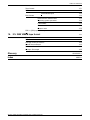
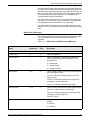
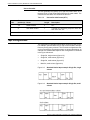
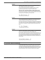
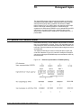
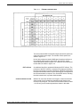
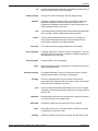
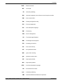
Table 2-2 shows the principal differences between IBM standard
labeled tape structures and ANSI tape structures.
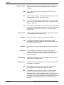
Figure 2-1.
2-2
IBM labeled tape structure
XEROX LASER PRINTING SYSTEMS TAPE FORMATS MANUAL
IBM OS/360 AND DOS/360 STANDARD LABELED TAPES
*
HDR2, EOV2, and EOF2 are provided under OS/360 but not under
DOS/360. Note that optional labels are not shown.
**
Multiple file tapes created under DOS/360 must be created with the
DTF TPMARK = NO specification to avoid incorrectly placing two
tape marks between files.
Table 2- 2.
ANSI and IBM labeled tape structure
Feature
ANSI labels
IBM OS/360 standard labels
Tape marks
A double tape mark follows the last EOF A double tape mark follows only the last
or EOV label group on a tape to indicate EOF label group on a tape. This
the end of recorded data on the tape.
indicates that end of recorded data has
been encountered, and there is not a
continuation reel.
VOL
VOL1 only.
OS:VOL1 only
DOS:VOL1 provided.
VOL2-9 permitted.
UVL
1-9 allowed.
None allowed
HDR, EOF, EOV
1 required; 2-9 optional.
OS:1 and 2 provided.
DOS:1 provided; additional labels not
used.
UHL, UTL
These are limited only by the 63
USASCII graphics available as “a”
characters for the label “number.”
Only UHL 1-8 allowed.
Recorded code
USASCII
EBCDIC
XEROX LASER PRINTING SYSTEMS TAPE FORMATS MANUAL
2-3
IBM OS/360 AND DOS/360 STANDARD LABELED TAPES
Figure 2-2.
*
**
2-4
IBM standard label groups
For the first file on a volume, HDR1 immediately follows the last
volume label without an intervening tape mark.
HDR2, EOV2, and EOF2 are created by OS/360 but not DOS/360.
XEROX LASER PRINTING SYSTEMS TAPE FORMATS MANUAL
IBM OS/360 AND DOS/360 STANDARD LABELED TAPES
VOL1 label
This label is always the first record on a tape. The format is described
in table 2-3.
Table 2- 3.
VOL1 label (IBM tapes)
Name
Character
position(s)
Field
Description
Label identifier
1-3
1
This is the 3-character identifier VOL.
Label number
4
2
This is the number 1.
Volume serial number
5-10
3
This is an identification code assigned to the volume
when it enters the system.
Reserved
11
4
Zero.
VTO pointer (direct access
only)
12-21
5
Blanks.
Reserved
22-31
6
Blanks.
Reserved
32-41
7
Blanks.
Owner name and address
code
42-51
8
This identifies the owner of the volume.
Reserved
52-80
9
Blanks.
VOL2 through VOL8 labels
These labels are optional under DOS/360 and are bypassed by the
Xerox/OSS.
XEROX LASER PRINTING SYSTEMS TAPE FORMATS MANUAL
2-5
IBM OS/360 AND DOS/360 STANDARD LABELED TAPES
HDR1, EOV1, EOF1 labels
The formats of these labels are identical except for block count. The
formats are shown in table 2-4.
Table 2- 4.
HDR1, EOV1, and EOF1 labels (IBM tapes)
Name
Character
position(s)
Field
Description
Label identifier
1-3
1
This is the 3-character identifier HDR, EOV, or EOF.
Label number
4
2
This is the number 1.
File identifier*
5-21
3
These are the rightmost 17 bytes of the file name and
includes GnnnVnn if part of a generation data group.
File serial number
22-27
4
This is the volume serial number of the tape volume
containing the file.
Volume sequence number*
28-31
5
This number (0001-9999) indicates the order of the
volume within the multi-volume group created at the
same time.
File sequence
32-35
6
This number (0001-9999) indicates the relative
position of the file within a multi-file group.
Generation number
36-39
7
This field contains a number from 0000 to 9999
indicating the absolute generation number if the file is
part of a generation data group (the first generation is
0000).
Version number
40-41
8
This field contains a number from 00 to 99 indicating
the version number of the generation if the file is part
of a generation data group (the first version is 00).
Creation date
42-47
9
This is the year and day the file was created and is of the
form: byyddd
b = blank
yy = year (00-99)
ddd = day (001-366)
Expiration date
48-53
10
This is the year and day when the file may be
scratched or overwritten. The data is of the same form
as described for creation date
File security
54
11
0 means no security.
1 means security protection; additional ID of file
required before it can be read, written, or deleted.
3 means security protection; additional ID of file
required before it can be read, written, or deleted.
Block count*
55-60
12
This is the number of data blocks in the file on the
current volume (exclusive of labels and tape marks).
For HDR1, this field contains zeros.
System code
61-73
13
This code identifies the system.
Reserved
74-80
14
Blanks.
*Fields 3, 5, and 12 are used by the operating system.
2-6
XEROX LASER PRINTING SYSTEMS TAPE FORMATS MANUAL
IBM OS/360 AND DOS/360 STANDARD LABELED TAPES
The HDR1 label is always the first beginning-of-file label. When the
file is the first on the tape, the HDR1 label immediately follows the last
VOL label without an intervening tape mark. When the file is not the
first on the tape, HDR1 is the first block following the tape mark that
followed the previous end-of-file label group. The HDR1 label is
created by both OS/360 and DOS/360.
The EOV1 label is always the first (or only) label following the last
data block on a tape when a file is continued on a succeeding tape.
It is separated from the final data block by a tape mark.
The EOF1 label is always the first (or only) label following the last
data block of a file. It is separated from the final data block by a tape
mark.
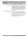
HDR2, EOV2, EOF2 labels
The formats of these labels are identical and are described in table
2-5. Only HDR2 labels are processed. EOV2 and EOF2 are
bypassed.
Table 2- 5.
HDR2, EOV2, and EOF2 labels (IBM tapes)
Name
Character
position(s)
Field
Description
Label identifier
1-3
1
This is the 3-character identifier HDR, EOV, or EOF.
Label number
4
2
This is the number 2.
Record format*
5
3
This is an alphabetic character that indicates the
format of the records in the associated file. The
characters are:
F = fixed length.
V = variable length.
U = undefined length.
Block length*
6-10
4
This is a binary number (up to 32,764) that indicates
the block length in bytes.
Format F—Must be an integral multiple of record
length (field 5).
Format V—Indicates maximum block length in file,
including the 4-byte length field.
Format U—Indicates maximum block length.
Record length*
11-15
5
This is a number that indicates record length in bytes.
Format F—Indicates actual record length.
Format V—Indicates maximum record length in file,
including the 4-byte length field.
Format U—Zeros.
Tape density
16
6
This is a code that indicates the recording density of
the tape.
2 = 800 bpi
3 = 1600 bpi
* Fields 3, 4, 5, and 12 are used by the operating system.
XEROX LASER PRINTING SYSTEMS TAPE FORMATS MANUAL
2-7
IBM OS/360 AND DOS/360 STANDARD LABELED TAPES
Table 2- 5.
HDR2, EOV2, and EOF2 labels (IBM tapes)
(continued)
Name
Character
position(s)
Field
Description
File position
17
7
This is a code that indicates a volume switch.
0 indicates no volume switch has occurred;
1 indicates a volume switch has occurred.
Job/job step identification
18-34
8
This is an indication of the job/job step that created
the file.
Tape recording technique
35-36
9
This is either a code for 7-track tapes or blanks for 9track tapes.
Printer control character
37
10
This is a code indicating whether a control character
set was used to create the file, and the type of control
characters used:
A = ANSI control characters.
M = machine control characters.
blank = no control characters.
Reserved
38
11
Blank.
Block attribute*
39
12
This is a code indicating the block attribute used to
create the file. The codes are:
B = blocked records.
S = spanned records.
R = blocked and spanned records.
blank = not blocked and not spanned records.
Reserved
40-80
13
Blanks.
* Fields 3, 4, 5, and 12 are used by the operating system.
The HDR2 label is always created by OS/360 and immediately
follows HDR1 on OS/360 standard labeled tapes. It is not created by
DOS/360. The HDR2 label provides data relating to the physical
parameters of the recorded file such as record format, record length,
and block length.
The EOV2 label is always created by OS/360 and immediately
follows EOV1 on OS/360 standard labeled tapes. It is not created by
DOS/360.
The EOF2 label is always created by OS/360 and immediately
follows EO1 on OS/360 standard labeled tapes. It is not created by
DOS/360.
2-8
XEROX LASER PRINTING SYSTEMS TAPE FORMATS MANUAL
IBM OS/360 AND DOS/360 STANDARD LABELED TAPES
UHL1-8, UTL1-8 labels
These are optional user labels and are bypassed by the Xerox/OSS.
Their formats are described in table 2-6.
Table 2- 6.
UHL and UTL labels (IBM tapes)
Name
Character
position(s)
Field
Description
Label identifier
1-3
1
This is the 3-character identifier UHL or UTL.
Label number
4
2
This is a number from 1 to 8.
User option
5-80
3
Specified by user
The UHLn labels immediately follow HDR2 for OS/360 and HDR1 for
DOS/360.
The UTLn labels immediately follow EOV2 for OS/360 and EOV1 for
DOS/360.
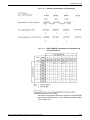
Printer carriage control conventions
The Xerox/OSS accepts IBM 1401 “Emulation” control characters,
IBM 1403 “Machine” control characters, and IBM ANSI control
characters.
Table 2- 7.
IBM 1401 emulation control codes
Code (hexadecimal) 1401 function
Code (hexadecimal) 1401 function
E1
Print, space 1 line.
D1
No print, space 1 line.
E2
Print, space 2 lines.
D2
No print, space 2 lines.
E3
Print, space 3 lines.
D3
No print, space 3 lines.
C1
Print, skip to channel 1.
F1
No print, skip to channel 1.
C2
Print, skip to channel 2.
F2
No print, skip to channel 2.
C3
Print, skip to channel 3.
F3
No print, skip to channel 3.
C4
Print, skip to channel 4.
F4
No print, skip to channel 4.
C5
Print, skip to channel 5
F5
No print, skip to channel 5.
C6
Print, skip to channel 6.
F6
No print, skip to channel 6.
C7
Print, skip to channel 7
F7
No print, skip to channel 7.
C8
Print, skip to channel 8.
F8
No print, skip to channel 8.
C9
Print, skip to channel 9
F9
No print, skip to channel 9.
C0
Print, skip to channel 10.
F0
No print, skip to channel 10.
4B
Print, skip to channel 11.
7B
No print, skip to channel 11.
4C
Print, skip to channel 12.
7C
No print, skip to channel 12.
XEROX LASER PRINTING SYSTEMS TAPE FORMATS MANUAL
2-9
IBM OS/360 AND DOS/360 STANDARD LABELED TAPES
Table 2- 8.
IBM 1403 emulation control codes
Code
(hexadecimal) 1403 function
Code
(hexadecimal) 1401 function
01
Write (no automatic space)*
0B
Space 1 line immediately.
02
Write and space 1 line after printing.
13
Space 2 line immediately.
11
Write and space 2 line after printing.
1B
Space 3 line immediately.
19
Write and space 3 line after printing
8B
Skip to channel 1 immediately.
89
Write and skip to channel 1 after printing. 93
Skip to channel 2 immediately.
91
Write and skip to channel 2 after printing. 9B
Skip to channel 3 immediately.
99
Write and skip to channel 3 after printing. A3
Skip to channel 4 immediately.
A1
Write and skip to channel 4 after printing. AB
Skip to channel 5 immediately.
A9
Write and skip to channel 5 after printing. B3
Skip to channel 6 immediately.
B1
Write and skip to channel 6 after printing. BB
Skip to channel 7 immediately.
B9
Write and skip to channel 7 after printing. C3
Skip to channel 8 immediately.
C1
Write and skip to channel 8 after printing. CB
Skip to channel 9 immediately.
C9
Write and skip to channel 9 after printing. D3
Skip to channel 10 immediately.
D1
Write and skip to channel 10 after printing. DB
Skip to channel 11 immediately.
D9
Write and skip to channel 11 after printing. E3
Skip to channel 12 immediately.
E1
Write and skip to channel 12 after printing. 03
No operation.
*A record with a write-type control character immediately preceded by a record with the “Write (no automatic
space)” control character is processed according to the option selected for overprint handling.
The processing parameters for IBM 1401 and IBM 1403 carriage
control are as follows:
2-10
IBM 1401
IBM 1403
INITIAL
TOF
TOF
DEFAULT
(OVR,PSPI)
(OVR,PSPI)
ADVTAPE
YES
NO
MASK
X‘FF‘
X‘FF‘
ASSIGN
See values in table 2-7
See values in table 2-8.
XEROX LASER PRINTING SYSTEMS TAPE FORMATS MANUAL
IBM OS/360 AND DOS/360 STANDARD LABELED TAPES
IBM OS and DOS tape JSL sample
The following figure provides a JSL sample.
Figure 2-3.
JSL sample for IBM OS, DOS, ANSI, WRITER tapes.
IBMRCA:JDL;
/*
*/
/*
SYSTEM TO PRINT IBM OS STANDARD AND DOS STANDARD
*/
/*
LABELED TAPES, IBM ANSI LABELED TAPES, IBM OS
*/
/*
WRITER TAPES, AND US70 (RCA) LABELED TAPES.
*/
/*
*/
V1:
VFU
ASSIGN=(1,5), ASSIGN=(2,10), ASSIGN=(3,15),
ASSIGN=(4,20), ASSIGN=(5,25), ASSIGN=(6,30),
ASSIGN=(7,35), ASSIGN=(8,40), ASSIGN=(9,45),
ASSIGN=(10,50), ASSIGN=(11,55), ASSIGN=(12,60),
TOF=5, BOF=66;
/*
*/
/*
VFU FOR OS WRITER WITH CHANNEL 9 ASSIGNED TO LINE 66
*/
/*
*/
WR:
VFU
ASSIGN=(1,5), ASSIGN=(2,10), ASSIGN=(3,15),
ASSIGN=(4,20), ASSIGN=(5,25), ASSIGN=(6,30),
ASSIGN=(7,35), ASSIGN=(8,40), ASSIGN=(10,45),
ASSIGN=(11,50), ASSIGN=(12,60), ASSIGN=(9,66),
TOF=5, BOF=66;
/*
*/
VOLUME
HOST=IBMOS, LABEL=STANDARD, CODE=EBCDIC,PLABEL=YES;
LINE
DATA=(1,132), PCCTYPE=ANSI, PCC=(0,NOTRAN),
OVERPRINT=(MERGE,NODISP), VFU=V1;
ACCT
USER=(BIN,TRAY);
/*
*/
/*
CATALOG FOR OS VARIABLE BLOCKED TAPES
*/
/*
*/
OSVB:CATALOG;
BLOCK
LENGTH=2660, PREAMBLE=4, LTHFLD=2, FORMAT=BIN;
RECORD
LENGTH=136, PREAMBLE=4, STRUCTURE=VB,
LTHFLD=2, OFFSET=0, FORMAT=BIN;
/*
*/
/*
CATALOG FOR OS WRITER TAPES
*/
/*
*/
OS:CATALOG;
VOLUME
HOST=OSWTR, OSCHN=9, OSTLP=0, OSHDP=1,
PLABEL=YES;
BLOCK
LENGTH=2400, PREAMBLE=4, LTHFLD=2, FORMAT=BIN;
RECORD
LENGTH=136, PREAMBLE=4, STRUCTURE=VB,
LTHFLD=2, FORMAT=BIN;
LINE
DATA=(1,132), PCCTYPE=ANSI, PCC=(0,NOTRAN),
OVERPRINT=(MERGE,NODISP), VFU=WR;
XEROX LASER PRINTING SYSTEMS TAPE FORMATS MANUAL
000010
000020
000030
000040
000050
000060
000070
000080
000090
000100
000110
000120
000130
000140
000150
000160
000170
000180
000190
000200
000210
000220
000230
000240
000250
000260
000270
000280
000290
000300
000310
000320
000330
000340
000350
000360
000370
000380
000390
000400
000410
000420
2-11
IBM OS/360 AND DOS/360 STANDARD LABELED TAPES
/*
/*
CATALOG FOR UNIVAC SERIES 70
/*
(FORMERLY RCA)
/*
US:CATALOG;
VOLUME
HOST=US70, LABEL=STANDARD, PLABEL=YES;
BLOCK
LENGTH=1330, PREAMBLE=0;
RECORD
LENGTH=133, STRUCTURE=FB;
LINE
DATA=(1,132), PCCTYPE=US70, PCC=(0,NOTRAN),
OVERPRINT=(MERGE,NODISP), VFU=V1;
/*
/*
IBM OS/DOS STANDARD LABELED TAPES
/*
------------------------------------------/*
/*
THE FOLLOWING JDES PROVIDE SUPPORT FOR IBM OS STANDARD
/*
AND IBM DOS STANDARD LABELED TAPES
/*
/*
CHARACTERISTICS
JOB
/*
---------------------/*
/*
OS STANDARD LABELS, 1403 PCC
1
/*
OS STANDARD LABELS, ANSI PCC
2
/*
OS STANDARD LABELS, 1401 PCC
3
/*
OS STANDARD LABELS, NO PCC
4
/*
DOS STANDARD LABELS, 1403 PCC
5
/*
DOS STANDARD LABELS, ANSI PCC
6
/*
DOS STANDARD LABELS, 1401 PCC
7
/*
DOS STANDARD LABELS, NO PCC
8
/*
1:JOB INCLUDE=(OSVB);
VOLUME
HOST=IBMOS, LABEL=STANDARD, CODE=EBCDIC;
LINE
PCCTYPE=IBM1403;
2:JOB INCLUDE=(OSVB);
VOLUME
HOST=IBMOS, LABEL=STANDARD, CODE=EBCDIC;
LINE
PCCTYPE=ANSI;
3:JOB INCLUDE=(OSVB);
VOLUME
HOST=IBMOS, LABEL=STANDARD, CODE=EBCDIC;
LINE
PCCTYPE=IBM1401;
4:JOB INCLUDE=(OSVB);
VOLUME
HOST=IBMOS, LABEL=STANDARD, CODE=EBCDIC;
LINE
PCCTYPE=NONE;
5:JOB;
VOLUME
HOST=IBMDOS, LABEL=STANDARD, CODE=EBCDIC;
LINE
PCCTYPE=IBM1403;
6:JOB;
VOLUME
HOST=IBMDOS, LABEL=STANDARD, CODE=EBCDIC;
LINE
PCCTYPE=ANSI;
7:JOB;
VOLUME
HOST=IBMDOS,LABEL=STANDARD, CODE=EBCDIC;
LINE
PCCTYPE=IBM1401;
8:JOB;
VOLUME
HOST=IBMDOS, LABEL=STANDARD, CODE=EBCDIC;
LINE
PCCTYPE=NONE;
2-12
*/
*/
*/
*/
*/
*/
*/
*/
*/
*/
*/
*/
*/
*/
*/
*/
*/
*/
*/
*/
*/
*/
*/
000430
000440
000450
000460
000470
000480
000490
000500
000510
000520
000530
000540
000550
000560
000570
000580
000590
000600
000610
000620
000630
000640
000650
000660
000670
000680
000690
000700
000710
000720
000730
000740
000750
000760
000770
000780
000790
000800
000810
000820
000830
000840
000850
000860
000870
000880
000890
000900
000910
000920
000930
000940
000950
XEROX LASER PRINTING SYSTEMS TAPE FORMATS MANUAL
IBM OS/360 AND DOS/360 STANDARD LABELED TAPES
/*
*/
/*
IBM ANSI LABELED AND OS WRITER TAPES
*/
/*
---------------------------------------------- */
/*
*/
/*
THE FOLLOWING JDES PROVIDE SUPPORT FOR IBM ANSI LABELED */
/*
TAPES AND OS WRITER TAPES.
*/
/*
*/
/*
CHARACTERISTICS
JOB
*/
/*
---------------------*/
/*
*/
/*
ANSI LABELS, ASCII CODE, ANSI PCC
21
*/
/*
ANSI LABELS, ASCII CODE, NO PCC
22
*/
/*
OS WRITER, ANSI PCC
23
*/
/*
OS WRITER, 1403 PCC
24
*/
/*
*/
21:JOB;
VOLUME
HOST=IBMOS, LABEL=ANSI, CODE=ASCII, LCODE=ASCII;
LINE
PCCTYPE=ANSI;
22:JOB;
VOLUME
HOST=IBMOS, LABEL=ANSI, CODE=ASCII, LCODE=ASCII;
LINE
PCCTYPE=NONE;
23:JOB
INCLUDE=(OS);
VOLUME
HOST=OSWTR;
LINE
PCCTYPE=ANSI;
24:JOB
INCLUDE=(OS);
VOLUME
HOST=OSWTR;
LINE
PCCTYPE=IBM1403;
/*
*/
/*
US70 (RCA) STANDARD LABELED TAPES
*/
/*
------------------------------------------*/
/*
*/
/*
JDES 41 AND 42 PROVIDE SUPPORT FOR US70 (FORMERLY RCA)
*/
/*
STANDARD LABELED TAPES.
*/
/*
*/
41:JOB
INCLUDE=(US);
VOLUME
HOST=US70, LABEL=STANDARD;
END;END;
XEROX LASER PRINTING SYSTEMS TAPE FORMATS MANUAL
000960
000970
000980
000990
001000
001010
001020
001030
001040
001050
001060
001070
001080
001090
001100
001110
001120
001130
001140
001150
001160
001170
001180
001190
001200
001210
001220
001230
001240
001250
001260
001270
001280
001290
001300
001310
001320
2-13
IBM OS/360 AND DOS/360 STANDARD LABELED TAPES
2-14
XEROX LASER PRINTING SYSTEMS TAPE FORMATS MANUAL
3.
3 IBM DOS/360 GRASP tape
organization
This chapter describes the IBM DOS/360 GRASP tape organization.
It also includes a sample JSL.
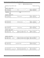
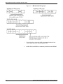
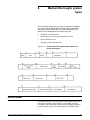
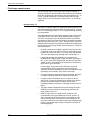
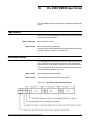
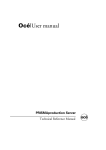
Record format
Each physical record on a GRASP tape consists of two basic
elements: the identification segment and a segment containing a
variable number of logical data records (refer to figure 3-1).
Figure 3-1.
GRASP physical record format
•
B0 is a byte which contains the length of the ID segment in
binary.
•
B1 is used as a flag byte. If bit zero of byte 1 is set to 1, then the
first logical record following the ID segment contains a line up
message-to be used for job control information by the operator.
•
ID DATA, bytes 26 and 27 (zero-indexing from the start of the
block) contain the address of the phantom printer device to be
used for block selection/deletion criteria, if desired.
•
F1 is a one-byte binary value which gives the length of F3. A
zero value implies end of logical records in block.
•
F2 is the channel control word after resetting bit 5 to zero. In a
line-up record, the channel control word stored here is treated
as a “no operation” (NOP) by the printer.
•
F3 is either a line-up message or a line of print data.
XEROX LASER PRINTING SYSTEMS TAPE FORMATS MANUAL
3-1
Identification segment
The identification segment is a logical record used by GRASP. It
consists of a length byte (byte 0), a flag byte (byte 1), and
identification data used only by GRASP.
•
The length byte contains the length of the identification
segment, including the length byte, flag byte, and identification
data.
•
Bit 0 of the flag byte is set to one if the current data block
contains a line-up record. This line-up record, if present,
appears as the first logical data record in the block.
Data records
The logical data records consist of three fields.
•
Field one contains a one-byte binary value which specifies the
length of field three. If zero is specified, the end of logical
records in the current physical record is indicated.
•
Field two contains a one-byte code which, after turning off bit
five, should be used as the IBM System 360/370 (1403) printer
carriage control code.
•
Field three is the print line data. The length of the data is
specified in field one.
GRASP tapes are single file tapes ending with a single tape mark.
Multiple reel tapes are signified by an ending tape mark coinciding
with an EOT reflector.
Line-up records
Line-up records conform to the field three format mentioned
previously. The length byte of the line-up record includes the length
of the message identifier and the length of the message text. To
locate the message text, scan the record for a hexadecimal 15
(X'15'). The text of the message begins with the character
immediately following the hexadecimal 15. The channel control word
in the line-up record is the code for a printer “no operation” (NOP).
Physical record size
The physical record size for each block of data on a GRASP tape is
equal to the GRASP disk buffer size. This buffer size is specified at
GRASP generation time and must be obtained from the user
installation's software support group.
XEROX LASER PRINTING SYSTEMS TAPE FORMATS MANUAL
3-2
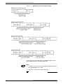
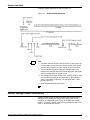
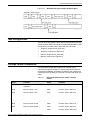
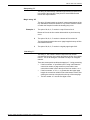
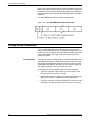
Sample data block
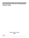
A sample GRASP data block is shown in figure 3-2.
Figure 3-2.
Sample GRASP data block
Note:
1. This block does not contain a line-up record. If it did, the line-up
record would be in the first logical record position and it would
have the same format as all other logical records in the block.
2. The identification segment length byte includes itself in the
length count, while the data record length byte gives the length
of the print data within the logical record.
3. The carriage control bytes shown in this example could be used
directly without resetting bit 5 (it is already 0). “0B” indicates
space 1 immediate (no printing), “09” indicates space 1 after
printing, and so on.
4. CCW indicates channel control word.
GRASP carriage control conventions
GRASP carriage control is identical to IBM 1403 carriage control
except bit five (counting from the left of the byte) is set. This is
equivalent to adding binary four to each of the IBM 1403 control
codes. For example, GRASP code X'0D' is processed as 1403 code
X'09', or “print and space one line.”
XEROX LASER PRINTING SYSTEMS TAPE FORMATS MANUAL
3-3
GRASP interspersed block tapes
GRASP can produce interspersed block tapes by using multiple
phantom printers. Byte 27 of each block (in the ID segment of each
block) contains the address of a phantom printer. To process these
requests, the user should set up a block selection/deletion function.
XEROX LASER PRINTING SYSTEMS TAPE FORMATS MANUAL
3-4
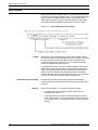
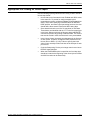
POWER and GRASP tapes
The following figure provides a JSL sample.
Figure 3-3.
POWGRP:JDL;
/*
/*
/*
V1:
VFU
/*
/*
/*
/*
T1:
T2:
JSL sample for POWER and GRASP tapes
SYSTEM FOR POWER, POWER VS, AND GRASP
ASSIGN=(1,5), ASSIGN=(2,10), ASSIGN=(3,15),
ASSIGN=(4,20), ASSIGN=(5,25), ASSIGN=(6,30),
ASSIGN=(7,35), ASSIGN=(8,40), ASSIGN=(9,45),
ASSIGN=(10,50), ASSIGN=(11,55), ASSIGN=(12,60),
TOF=4, BOF=66;
TABLES AND CRITERIA FOR LOGICAL PROCESSING
FOR GRASP INTERLEAVED TAPES
TABLE
TABLE
*/
*/
*/
*/
CONSTANT=('B');
CONSTANT=('C');
/*
C1:
C2:
*/
*/
*/
*/
CRITERIA CONSTANT=(27,1,EQ,T1);
CRITERIA CONSTANT=(27,1,EQ,T2);
/*
/*
/*
SYSTEM FOR POWER VS
VOLUME
BLOCK
RECORD
LINE
ACCT
/*
/*
/*
PW:CATALOG;
VOLUME
BLOCK
RECORD
/*
/*
/*
GR:CATALOG;
VOLUME
BLOCK
RECORD
*/
*/
*/
HOST=POWERVS, PLABEL=YES;
LENGTH=2048;
LENGTH=136, STRUCTURE=VB, LTHFLD=2, OFFSET=0,
ADJUST=0, FORMAT=BIN, PREAMBLE=3;
DATA=(1,132), PCCTYPE=IBM1403, PCC=(0,NOTRAN),
OVERPRINT=(MERGE,NODISP), VFU=V1;
USER=(BIN,TRAY);
CATALOG FOR POWER VERSIONS
*/
*/
*/
HOST=POWER;
LENGTH=2048, PREAMBLE=6, LTHFLD=2, FORMAT=BIN,
OFFSET=4;
LENGTH=135, STRUCTURE=VB, PREAMBLE=2,
LTHFLD=2, FORMAT=BIN, OFFSET=0, ADJUST=3;
CATALOG FOR GRASP
*/
*/
*/
HOST=GRASP;
LENGTH=4096, PREAMBLE=0, ZERO=YES;
LENGTH=135, STRUCTURE=VB, PREAMBLE=1,
LTHFLD=1, FORMAT=BIN, OFFSET=0, ADJUST=2;
/*
*/
RSTACK
TEST=(C1,OR,C2), DELIMITER=YES, PRINT=TRAY;
/*
/*
XEROX LASER PRINTING SYSTEMS TAPE FORMATS MANUAL
*/
*/
000010
000020
000030
000040
000050
000060
000070
000080
000090
000100
000110
000120
000130
000140
000150
000160
000170
000180
000190
000200
000210
000220
000230
000240
000250
000260
000270
000280
000290
000300
000310
000320
000330
000340
000350
000360
000370
000380
000390
000400
000410
000420
000430
000440
000450
000460
000470
000480
000490
3-5
/*
/*
/*
/*
/*
/*
/*
/*
/*
/*
/*
/*
/*
1:JOB;
2:JOB
3:JOB
/*
/*
/*
/*
/*
/*
/*
/*
/*
/*
/*
/*
/*
/*
/*
21:JOB
22:JOB
23:JOB
/*
/*
END;END;
POWER VS, POWER 4.0, AND POWER 4.1/4.2
--------------------------------------
*/
*/
*/
THE FOLLOWING JDES PROVIDE SUPPORT FOR IBM POWER VS TAPES,*/
POWER VERSION 4.0 TAPES, AND POWER VERSIONS 4.1/4.2 TAPES */
*/
CHARACTERISTICS
JOB
*/
---------------------*/
*/
POWER VS TAPES
1
*/
POWER VERSION 4.0 TAPES
2
*/
POWER VERSIONS 4.1/4.2 TAPES
3
*/
*/
VOLUME
HOST=POWERVS;
INCLUDE=(PW);
VOLUME
HOST=POWER;
RECORD
LTHFLD=1, PREAMBLE=1, ADJUST=2;
INCLUDE=(PW);
VOLUME
HOST=POWER;
IBM DOS GRASP TAPES
------------------THE FOLLOWING JDES PROVIDE SUPPORT FOR GRASP TAPES
CHARACTERISTICS
---------------
JOB
--------
NORMAL GRASP TAPES
GRASP WITH INTERSPERSED REPORTS - SELECT
REPORTS FROM PHANTOM DEVICE B
GRASP WITH INTERSPERSED REPORTS - DELETE
REPORTS FROM PHANTOM DEVICE C
21
22
23
*/
*/
*/
*/
*/
*/
*/
*/
*/
*/
*/
*/
*/
*/
*/
INCLUDE=(GR);
VOLUME
HOST=GRASP;
INCLUDE=(GR);
VOLUME
HOST=GRASP;
BSELECT TEST=(C1);
INCLUDE=(GR);
VOLUME
HOST=GRASP;
BSELECT TEST=(C2);
END OF POWER AND GRASP SYSTEM
XEROX LASER PRINTING SYSTEMS TAPE FORMATS MANUAL
*/
*/
000500
000510
000520
000530
000540
000550
000560
000570
000580
000590
000600
000610
000620
000630
000640
000650
000660
000670
000680
000690
000700
000710
000720
000730
000740
000750
000760
000770
000780
000790
000800
000810
000820
000830
000840
000850
000860
000870
000880
000890
000900
000910
000920
000930
000940
000950
3-6
4.
4IBM DOS/360 POWER II tape
organization
This chapter describes the IBM DOS/360 POWER II tape
organization. It also includes tape format examples and a sample
JSL.
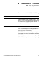
Tape formats
The Xerox/OSS accepts labeled tapes produced by IBM
DOS/360 POWER II, Versions 4.0, 4.1, and 4.2. POWER
II produces tapes with one 20-byte header label, variable
length blocks up to 1024 bytes long, and blocks with
variable length records. Each block is preceded by a 6byte prefix which contains the block size in bytes
(including the block prefix). Each record has a prefix
which contains the record length field and carriage control
information.
Block version characteristics (4.0, 4.1, 4.2)
The block Version 4.0 format is shown in figure 4-1.
Figure 4-1.
XEROX LASER PRINTING SYSTEMS TAPE FORMATS MANUAL
POWER Version 4.0, block format
4-1
IBM DOS/360 POWER II TAPE ORGANIZATION
•
The 20-byte header label contains the characters
PRTRDRPUN in the first 9 positions followed by 11 blanks.
(This is the same as Version 4.0.)
•
Each block begins with a 6-byte block prefix which contains the
block length in bytes in the last 2 bytes of the prefix. (This is the
same as Version 4.0.)
•
Each record is prefaced with a 2-byte field. The first byte is the
length of the data portion of the record in bytes, and the second
byte is an IBM 1403 Machine Control Code used for carriage
control.
Version 4.1
The block Version 4.1 is shown in figure 4-2.
Figure 4-2.
POWER Version 4.1 and 4.2, block format
•
The 20-byte header label contains the characters
PRTRDRPUN in the first 9 positions followed by 11 blanks.
(This is the same as Version 4.0.)
•
Each block begins with a 6-byte block prefix which contains the
block length in bytes in the last 2 bytes of the prefix. (This is the
same as Version 4.0.)
•
Each record is prefaced with a 3-byte field. The first two bytes
contain the length of the data portion of the record in bytes, and
the third byte is an IBM 1403 Machine Control Code used for
carriage control.
Version 4.2
The block and record format for Version 4.2 is identical to Version
4.1. (Refer to previous section.)
4-2
XEROX LASER PRINTING SYSTEMS TAPE FORMATS MANUAL
IBM DOS/360 POWER II TAPE ORGANIZATION
Tape format examples
An example of a Version 4.0 POWER II tape is shown in figure 4-3.
An example of a Version 4.1 POWER II tape is shown in figure 4-4.
Figure 4-3.
POWER II, Version 4.0 sample tape format
First record, header label*
*
Header label contents shown are in hexadecimal.
Second record, block of data records
Figure 4-4.
POWER II, Version 4.1 sample tape format
First record, header label*
*
Header label contents shown are in hexadecimal.
XEROX LASER PRINTING SYSTEMS TAPE FORMATS MANUAL
4-3
IBM DOS/360 POWER II TAPE ORGANIZATION
POWER and GRASP tape JSL sample
The following figure provides a JSL sample.
Figure 4-5.
POWGRP:JDL;
/*
/*
/*
V1:
VFU
/*
/*
/*
/*
T1:
T2:
JSL sample for POWER and GRASP tapes.
SYSTEM FOR POWER, POWER VS, AND GRASP
ASSIGN=(1,5), ASSIGN=(2,10), ASSIGN=(3,15),
ASSIGN=(4,20), ASSIGN=(5,25), ASSIGN=(6,30),
ASSIGN=(7,35), ASSIGN=(8,40), ASSIGN=(9,45),
ASSIGN=(10,50), ASSIGN=(11,55), ASSIGN=(12,60),
TOF=4, BOF=66;
TABLES AND CRITERIA FOR LOGICAL PROCESSING
FOR GRASP INTERLEAVED TAPES
TABLE
TABLE
*/
CRITERIA CONSTANT=(27,1,EQ,T1);
CRITERIA CONSTANT=(27,1,EQ,T2);
/*
/*
/*
*/
*/
*/
SYSTEM FOR POWER VS
VOLUME
BLOCK
RECORD
LINE
ACCT
/*
/*
/*
PW:CATALOG;
VOLUME
BLOCK
RECORD
/*
/*
/*
GR:CATALOG;
VOLUME
BLOCK
RECORD
HOST=POWERVS, PLABEL=YES;
LENGTH=2048;
LENGTH=136, STRUCTURE=VB, LTHFLD=2, OFFSET=0,
ADJUST=0, FORMAT=BIN, PREAMBLE=3;
DATA=(1,132), PCCTYPE=IBM1403, PCC=(0,NOTRAN),
OVERPRINT=(MERGE,NODISP), VFU=V1;
USER=(BIN,TRAY);
CATALOG FOR POWER VERSIONS
*/
*/
*/
CATALOG FOR GRASP
HOST=GRASP;
LENGTH=4096, PREAMBLE=0, ZERO=YES;
LENGTH=135, STRUCTURE=VB, PREAMBLE=1,
LTHFLD=1, FORMAT=BIN, OFFSET=0, ADJUST=2;
*/
RSTACK
/*
/*
*/
*/
*/
HOST=POWER;
LENGTH=2048, PREAMBLE=6, LTHFLD=2, FORMAT=BIN,
OFFSET=4;
LENGTH=135, STRUCTURE=VB, PREAMBLE=2,
LTHFLD=2, FORMAT=BIN, OFFSET=0, ADJUST=3;
/*
4-4
*/
*/
*/
*/
CONSTANT=('B');
CONSTANT=('C');
/*
C1:
C2:
*/
*/
*/
TEST=(C1,OR,C2), DELIMITER=YES, PRINT=TRAY;
*/
*/
000010
000020
000030
000040
000050
000060
000070
000080
000090
000100
000110
000120
000130
000140
000150
000160
000170
000180
000190
000200
000210
000220
000230
000240
000250
000260
000270
000280
000290
000300
000310
000320
000330
000340
000350
000360
000370
000380
000390
000400
000410
000420
000430
000440
000450
000460
000470
000480
000490
XEROX LASER PRINTING SYSTEMS TAPE FORMATS MANUAL
IBM DOS/360 POWER II TAPE ORGANIZATION
/*
/*
/*
/*
/*
/*
/*
/*
/*
/*
/*
/*
/*
1:JOB;
2:JOB
3:JOB
/*
/*
/*
/*
/*
/*
/*
/*
/*
/*
/*
/*
/*
/*
/*
21:JOB
22:JOB
23:JOB
/*
/*
END;END;
POWER VS, POWER 4.0, AND POWER 4.1/4.2
--------------------------------------
*/
*/
*/
THE FOLLOWING JDES PROVIDE SUPPORT FOR IBM POWER VS TAPES,*/
POWER VERSION 4.0 TAPES, AND POWER VERSIONS 4.1/4.2 TAPES */
*/
CHARACTERISTICS
JOB
*/
---------------------*/
*/
POWER VS TAPES
1
*/
POWER VERSION 4.0 TAPES
2
*/
POWER VERSIONS 4.1/4.2 TAPES
3
*/
*/
VOLUME
HOST=POWERVS;
INCLUDE=(PW);
VOLUME
HOST=POWER;
RECORD
LTHFLD=1, PREAMBLE=1, ADJUST=2;
INCLUDE=(PW);
VOLUME
HOST=POWER;
IBM DOS GRASP TAPES
------------------THE FOLLOWING JDES PROVIDE SUPPORT FOR GRASP TAPES
CHARACTERISTICS
---------------
JOB
--------
NORMAL GRASP TAPES
GRASP WITH INTERSPERSED REPORTS - SELECT
REPORTS FROM PHANTOM DEVICE B
GRASP WITH INTERSPERSED REPORTS - DELETE
REPORTS FROM PHANTOM DEVICE C
21
22
23
*/
*/
*/
*/
*/
*/
*/
*/
*/
*/
*/
*/
*/
*/
*/
INCLUDE=(GR);
VOLUME
HOST=GRASP;
INCLUDE=(GR);
VOLUME
HOST=GRASP;
BSELECT TEST=(C1);
INCLUDE=(GR);
VOLUME
HOST=GRASP;
BSELECT TEST=(C2);
END OF POWER AND GRASP SYSTEM
XEROX LASER PRINTING SYSTEMS TAPE FORMATS MANUAL
*/
*/
000500
000510
000520
000530
000540
000550
000560
000570
000580
000590
000600
000610
000620
000630
000640
000650
000660
000670
000680
000690
000700
000710
000720
000730
000740
000750
000760
000770
000780
000790
000800
000810
000820
000830
000840
000850
000860
000870
000880
000890
000900
000910
000920
000930
000940
4-5
IBM DOS/360 POWER II TAPE ORGANIZATION
4-6
XEROX LASER PRINTING SYSTEMS TAPE FORMATS MANUAL
5.
5IBM POWER/VS and POWER/
VSE tape organization
This chapter describes the IBM POWER/VS and POWER/VSE tape
organization. It also includes example file formats and a sample JSL.
Tape formats
The Xerox printing system accepts tapes produced by IBM DOS/VS
POWER and DOS/VSE POWER as illustrated in figure 5-1. These
tapes have no labels per se; however, the first and last blocks of a
file, which are identical, have a special length and content and, in a
limited sense, act as labels. Figure 5-2 presents an example of one
such special block or POWER/VS.
File formats
A tape mark precedes the first file on the tape. A single tape mark
separates files, and two tape marks end the tape. A tape mark
encountered in conjunction with an end-of-tape reflector denotes an
end-of-volume condition. (Refer to figure 5-1.)
For POWER VS, the file consists of one 152-byte special block,
followed by data blocks as described below in the section “Data
formats.” The last block in the file is another 152-byte special block.
For POWER/VSE, both special blocks are 184 bytes long, although
their format remains the same otherwise.
For POWER/VSE II, both special blocks are 216 bytes long, although
their format remains the same otherwise.
XEROX LASER PRINTING SYSTEMS TAPE FORMATS MANUAL
5-1
IBM POWER/VS AND POWER/VSE TAPE ORGANIZATION
Data formats
The data formats are fixed length blocks with variable length records;
no block length fields are present. The record format has a 2-byte
length field, a general purpose byte, a carriage control byte from the
1403 carriage control set, and zero to 132 print characters. (See
figures 5-3 and 5-4 which illustrate block and record formats,
respectively.)
A general purpose byte gives record or block identification; the codes
and functions of this byte are listed and described in table 5-1.
Table 5-1.
5-2
General purpose byte-codes and functions
Codes
Functions
00,01
Normal record
02
3540 (floppy disk) record
04
End-of-data (occurs in the last record of
the last print data block in the file)
08
Break record
0C,0D
End-of-block for Version 30.1 of DOS/
VS POWER
10,11
End-of-block for Version 31 of DOS/VS
POWER and subsequent releases
20
End of 3540 records
XEROX LASER PRINTING SYSTEMS TAPE FORMATS MANUAL
IBM POWER/VS AND POWER/VSE TAPE ORGANIZATION
Figure 5-1.
POWER VS and POWER/VSE file formats
Interpretation
TM
=
Tape mark
DATA
=
One or more data blocks (see figure 5-3 for further details)
SB
=
Special block (see figure 5-2 for further details)
R
=
Reflector
XEROX LASER PRINTING SYSTEMS TAPE FORMATS MANUAL
5-3
IBM POWER/VS AND POWER/VSE TAPE ORGANIZATION
Figure 5-2.
Format of a POWER VS special block
Figure 5-3.
POWER VS data block format
Blocks are fixed in length with variable length records. There is no
block length field, block offset, or block postamble.
Figure 5-4.
POWER VS record format
See table 5-1, earlier in this chapter, for general purpose byte codes
and functions.
5-4
XEROX LASER PRINTING SYSTEMS TAPE FORMATS MANUAL
IBM POWER/VS AND POWER/VSE TAPE ORGANIZATION
POWER and GRASP tape JSL sample
The following figure provides a JSL sample.
Figure 5-5.
POWGRP:JDL;
/*
/*
/*
V1:
VFU
/*
/*
/*
/*
T1:
T2:
JSL sample for POWER and GRASP tapes
SYSTEM FOR POWER, POWER VS, AND GRASP
ASSIGN=(1,5), ASSIGN=(2,10), ASSIGN=(3,15),
ASSIGN=(4,20), ASSIGN=(5,25), ASSIGN=(6,30),
ASSIGN=(7,35), ASSIGN=(8,40), ASSIGN=(9,45),
ASSIGN=(10,50), ASSIGN=(11,55), ASSIGN=(12,60),
TOF=4, BOF=66;
TABLES AND CRITERIA FOR LOGICAL PROCESSING
FOR GRASP INTERLEAVED TAPES
TABLE
TABLE
*/
*/
*/
*/
CONSTANT=('B');
CONSTANT=('C');
/*
C1:
C2:
*/
*/
*/
*/
CRITERIA CONSTANT=(27,1,EQ,T1);
CRITERIA CONSTANT=(27,1,EQ,T2);
/*
/*
/*
SYSTEM FOR POWER VS
VOLUME
BLOCK
RECORD
LINE
ACCT
/*
/*
/*
PW:CATALOG;
VOLUME
BLOCK
RECORD
/*
/*
/*
GR:CATALOG;
VOLUME
BLOCK
RECORD
*/
*/
.*/
HOST=POWERVS, PLABEL=YES;
LENGTH=2048;
LENGTH=136, STRUCTURE=VB, LTHFLD=2, OFFSET=0,
ADJUST=0, FORMAT=BIN, PREAMBLE=3;
DATA=(1,132), PCCTYPE=IBM1403, PCC=(0,NOTRAN),
OVERPRINT=(MERGE,NODISP), VFU=V1;
USER=(BIN,TRAY);
CATALOG FOR POWER VERSIONS
*/
*/
*/
HOST=POWER;
LENGTH=2048, PREAMBLE=6, LTHFLD=2, FORMAT=BIN,
OFFSET=4;
LENGTH=135, STRUCTURE=VB, PREAMBLE=2,
LTHFLD=2, FORMAT=BIN, OFFSET=0, ADJUST=3;
CATALOG FOR GRASP
*/
*/
*/
HOST=GRASP;
LENGTH=4096, PREAMBLE=0, ZERO=YES;
LENGTH=135, STRUCTURE=VB, PREAMBLE=1,
LTHFLD=1, FORMAT=BIN, OFFSET=0, ADJUST=2;
/*
*/
RSTACK
TEST=(C1,OR,C2), DELIMITER=YES, PRINT=TRAY;
/*
/*
XEROX LASER PRINTING SYSTEMS TAPE FORMATS MANUAL
*/
*/
000010
000020
000030
000040
000050
000060
000070
000080
000090
000100
000110
000120
000130
000140
000150
000160
000170
000180
000190
000200
000210
000220
000230
000240
000250
000260
000270
000280
000290
000300
000310
000320
000330
000340
000350
000360
000370
000380
000390
000400
000410
000420
000430
000440
000450
000460
000470
000480
000490
5-5
IBM POWER/VS AND POWER/VSE TAPE ORGANIZATION
/*
POWER VS, POWER 4.0, AND POWER 4.1/4.2
*/
/*
-------------------------------------*/
/*
*/
/* THE FOLLOWING JDES PROVIDE SUPPORT FOR IBM POWER VS TAPES, */
/*
POWER VERSION 4.0 TAPES, AND POWER VERSIONS 4.1/4.2 TAPES*/
/*
*/
/*
CHARACTERISTICS
JOB
*/
/*
---------------------*/
/*
*/
/*
POWER VS TAPES
1
*/
/*
POWER VERSION 4.0 TAPES
2
*/
/*
POWER VERSIONS 4.1/4.2 TAPES
3
*/
/*
*/
1:JOB;
VOLUME
HOST=POWERVS;
2:JOB
INCLUDE=(PW);
VOLUME
HOST=POWER;
RECORD
LTHFLD=1, PREAMBLE=1, ADJUST=2;
3:JOB
INCLUDE=(PW);
VOLUME
HOST=POWER;
/*
*/
/*
IBM DOS GRASP TAPES
*/
/*
------------------*/
/*
*/
/*
THE FOLLOWING JDES PROVIDE SUPPORT FOR GRASP TAPES
*/
/*
*/
/*
CHARACTERISTICS
JOB
*/
/*
---------------------*/
/*
*/
/*
NORMAL GRASP TAPES
21
*/
/*
GRASP WITH INTERSPERSED REPORTS - SELECT
22
*/
/*
REPORTS FROM PHANTOM DEVICE B
*/
/*
GRASP WITH INTERSPERSED REPORTS - DELETE
23
*/
/*
REPORTS FROM PHANTOM DEVICE C
*/
/*
*/
21:JOB
INCLUDE=(GR);
VOLUME
HOST=GRASP;
22:JOB
INCLUDE=(GR);
VOLUME
HOST=GRASP;
BSELECT TEST=(C1);
23:JOB
INCLUDE=(GR);
VOLUME
HOST=GRASP;
BSELECT TEST=(C2);
/*
*/
/*
END OF POWER AND GRASP SYSTEM
*/
END;END;
5-6
000500
000510
000520
000530
000540
000550
000560
000570
000580
000590
000600
000610
000620
000630
000640
000650
000660
000670
000680
000690
000700
000710
000720
000730
000740
000750
000760
000770
000780
000790
000800
000810
000820
000830
000840
000850
000860
000870
000880
000890
000900
000910
000920
000930
000940
000950
XEROX LASER PRINTING SYSTEMS TAPE FORMATS MANUAL
6.
6UNIVAC Series 70 (US70)
magnetic tape organization
This chapter describes the UNIVAC Series 70 (formerly RCA Spectra
70 Magnetic Tapes) magnetic tape organization. It also describes
header and trailer labels, tape configurations, data formats, and
includes a sample JSL.
Labeled tapes
A minimum set of US70 standard labels includes a volume label
(VOL 1), one standard file header label (HDR1), and one end-of-file
trailer label (EOF1) or one standard end-of-volume label (EOV1).
The minimum set of labels may be expanded by adding up to seven
of each label type. For example, a file label could contain eight file
header labels, HDR1, HDR2, HDR3, up to and including HDR8.
Additionally, the user may include both user header labels (UHL) and
user trailer labels (UTL). Up to eight of each of these labels may be
used. For example, UHL1 through UHL8 and UTL1 through UTL8
can be added.
Label groups and sets
This section describes header label groups and sets, and trailer label
sets.
Header label group
The header label group consists of the volume label, file header
label, and user header label sets. These label sets are contiguous
within the header label. For example, if a HDR2 label is used, it must
follow a HDR1 label.
The header label group is always ended with a tape mark (see figure
6-1).
Figure 6-1.
XEROX LASER PRINTING SYSTEMS TAPE FORMATS MANUAL
Header label organization
6-1
UNIVAC SERIES 70 (US70) MAGNETIC TAPE ORGANIZATION
Header label sets
This section describes volume, file, and user labels.
Volume label
Volume labels provide a means of identifying a given tape. The
volume label set is the first label set on a tape. There may be up to
eight volume labels per tape, but the data field in volumes two (VOL2)
through eight (VOL8) are undefined. The contents of a VOL1 label
are contained in table 6-1. The contents of VOL2 through VOL8
labels are contained in table 6-2.
Table 6-1.
Volume label format (VOL1)
Field
Character
position(s) Name
Length
Description
1
1-3
Label identifier
3
VOL
2
4
Volume label number
1
1
3
5-10
Volume serial number
6
Identifies the volume
4
11
Volume security
1
0=No security
1=The volume has or had security protection
5
12-21
Not used for tape files
10
Ten spaces
6
22-31
Reserved
10
Ten spaces
7
32-41
Reserved
10
Ten spaces
8
42-51
Owner’s name and
address code
10
Identifies the owner of the volume
9
52-80
Reserved
29
Twenty-nine spaces
Note: Unused and reserved fields should be recorded as EBCDIC
spaces (hexadecimal 40).
Table 6-2.
Volume label format (VOL2 through VOL8)
Field
Character
position(s) Name
Length
Description
1
1-3
Label identifier
3
VOL
2
4
Volume label number
1
2 through 8 in ascending sequence
3
5-80
Unidentified
76
Any characters the user wishes
File header label
The standard file header label (HDR1) identifies a file and indicates
the sequence of the file within a multi-file set. Additionally, it contains
the volume serial number (identical to the volume one [VOL1] serial
number) and the sequence of a volume in a file for multi-volume files.
Each file on a volume with standard labels contains a standard
header label (see table 6-3). Additionally, the standard label may be
6-2
XEROX LASER PRINTING SYSTEMS TAPE FORMATS MANUAL
UNIVAC SERIES 70 (US70) MAGNETIC TAPE ORGANIZATION
followed by up to seven file header labels, HDR2 through HDR8 (see
table 6-4).
Table 6-3.
Standard header label format (HDR1)
Field
Character
position(s)
Name
1
1-3
Label indentifier 3
HDR
2
4
File header label 1
number
1
3
5-21
File identifier*
17
Identifies the entire file.
4
22-27
File serial
number
6
Identifies a file/volume relationship. This field is
identical to the volume label (field 3). On a multivolume file, this field is identical to the volume
serial number on the first volume.
5
28-31
Volume
sequence
number*
4
Indicates the sequence of a volume in file (00019999). Used with multi-volume files.
6
32-35
File sequence
number
4
Indicates the sequence of a file in a multifile set
(0001-9999).
7
36-39
Generation
number
4
Indicates the editions of the file (0001-9999).
8
40-41
Version number 5
of generation
Indicates the version of a generation of a file (0199).
9
42-47
Creation date
Indicates the year and the day of the year the file
was created. The format is:
Length
6
Description
Position Content
Meaning
1
Space
None
2-3
00-99
Year
4-6
001-366
Day of the year
March 4, 1967 would be entered as 6 7 0 6 3
10
48-53
Expiration date
6
Indicates the year and the day of the year the
volume may be written on. This field has the
same format as Field 9.
11
54
File security
1
0 = No security protection
1 = This file has security protection.
12
55-60
Block count
6
Six spaces. This field in the file header label is
not used.
13
61-70
Reserved
13
Thirteen spaces.
14
74-80
Reserved
7
Seven spaces.
* Fields 3 and 5 are used by the operating system.
XEROX LASER PRINTING SYSTEMS TAPE FORMATS MANUAL
6-3
UNIVAC SERIES 70 (US70) MAGNETIC TAPE ORGANIZATION
Table 6-4.
Header label format (HDR2 through HDR8)
Field
Character
position(s) Name
Length
Description
1
1-3
Label indentifier
3
HDR
2
4
File header label number 1
2 through 8 in ascending sequence
3
5-80
Undefined
Reserved
76
User header label
The user has the option of including up to eight user header labels on
a labeled volume. A user header label contains one field which
consists of any characters the user wishes to include. User header
labels, if included, follow the file header labels. Their contents are
contained in table 6-5.
Table 6-5.
User header label format (UHL)
Field
Character
position(s) Name
Length
Description
1
1-3
Label identifier
3
UHL
2
4
User label number
1
1 through 8 in ascending sequence within the
UHL set or UTL set.
3
5-80
User’s option
76
May contain any characters
Trailer labels
The trailer label group consists of the end-of-file or end-of-volume
trailer label sets and the user trailer label set. The end-of-file trailer
label set indicates the end of a file. It is followed by one tape mark
unless the file under consideration is the last file on the volume. In
this case, the end-of-file trailer label set is followed by two tape
marks. The end-of-volume trailer label set is used when a file is
continued on a subsequent volume. This label set is followed by two
tape marks.
The trailer label group format is shown in figure 6-2.
Figure 6-2.
6-4
Trailer label organization
XEROX LASER PRINTING SYSTEMS TAPE FORMATS MANUAL
UNIVAC SERIES 70 (US70) MAGNETIC TAPE ORGANIZATION
Trailer label sets
File trailer labels
The first label of a trailer label set is called the standard trailer label.
This is either an end-of-file (ECF1) label or an end-of-volume (EOV1)
label. An end-of-file label indicates the end of a given file; an end-ofvolume label indicates the end of useful data on a tape volume. The
contents of the standard trailer label are contained in table 6-6.
Table 6-6.
Standard file trailer label format
Field
Character
position(s) Name
Length
Description
1
1-3
3
EOF=End-of-file trailer label
Label identifier
EOV=End-of-volume trailer label
2
4
File trailer label number
1
1
3-11
5-54
Same as corresponding
fields in file header label
50
Same as corresponding fields in file header
label
12
55-60
Block count*
6
Indicates the number of data blocks written on
the file from the last file header label to the first
file trailer label, excluding tape marks and
checkpoint records.
13
61-73
Same as corresponding
fields in file header label
13
Same as corresponding fields in file header
label
14
74-80
Same as corresponding
fields in file header label
7
Same as corresponding fields in file header
label
* Field 12 is used by the operating system.
In addition to the standard trailer label, the user may specify up to
seven additional file trailer labels, EOF2 through EOF8 or EOV2
through EOV8. These labels, if used, would follow the standard trailer
label. Their contents are shown in table 6-7.
Table 6-7.
File trailer label format
Field
Character
position(s) Name
Length
1
1-3
3
Label identifier
Description
EOF=End-of-file trailer label
EOV=End-of-volume trailer label
2
4
File trailer label number
1
2 through 8 in ascending sequence within the
EOF set or EOV set.
3
5-80
Undefined
76
Reserved
XEROX LASER PRINTING SYSTEMS TAPE FORMATS MANUAL
6-5
UNIVAC SERIES 70 (US70) MAGNETIC TAPE ORGANIZATION
User trailer label
The user optionally may specify up to eight user trailer labels, UTL1
through UTL8. If used, these labels follow the file trailer labels. The
contents of these labels are contained in table 6-8.
Table 6-8.
User trailer label format (UTL)
Field
Character
position(s) Name
Length
Description
1
1-3
Label identifier
3
UTL
2
4
User label number
1
1 through 8 in ascending sequence within the
UHL set or UTL set.
3
5-80
User’s option
76
May contain any characters
Tape configurations
The organization of standard labeled tapes varies from user to user.
For example, optional labels may or may not be included, and tape
files may occupy many volumes. The four basic configurations that
can be processed by the printing system are enumerated below. An
example of a standard label tape for each configuration is contained
in the figure referenced.
•
•
•
•
6-6
Single file, single volume (figure 6-3)
Single file, multi-volume (figure 6-4)
Single file, multi-volume (figure 6-5)
Multi-file, multi-volume (figure 6-6)
Figure 6-3.
Standard labeled tape example: Single file, single
volume
Figure 6-4.
Standard labeled tape example: Single file, multivolume
XEROX LASER PRINTING SYSTEMS TAPE FORMATS MANUAL
UNIVAC SERIES 70 (US70) MAGNETIC TAPE ORGANIZATION
Figure 6-5.
Standard labeled tape example: Multi-file, single
volume
Figure 6-6.
Standard labeled tape example: Multi-file, multi
volume
Unlabeled tapes
Magnetic tapes that contain no labels may also be processed on the
printing system. Unlabeled tapes optionally may begin with a tape
mark. Files are separated by a tape mark and two tape marks follow
the last data file. An example of an unlabeled tape is shown in figure
6-7.
Figure 6-7.
Standard labeled tape example: Multi-file, multi
volume
Note: The first tape mark in this illustration is normally written on
output but may be omitted at the programmer's option.
XEROX LASER PRINTING SYSTEMS TAPE FORMATS MANUAL
6-7
UNIVAC SERIES 70 (US70) MAGNETIC TAPE ORGANIZATION
Tape marks
This section describes labeled and unlabeled tape marks.
Labeled tapes
A tape mark follows every header label group and precedes and
follows every trailer label group. Two tape marks following a trailer
label group indicate the end of data on a volume. Figure 6-8 shows
an example of tape mark placement for standard labeled tapes.
Figure 6-8.
Null files
Tape mark placement: Tapes with standard labels,
additional labels, and user labels
It is possible, however, for two consecutive tape marks to appear on
tape and not signify the end of useful data on the volume. This
condition (null file) occurs when the end-of-volume and end-of-file
coincide (see figure 6-9).
Figure 6-9.
Note:
Tape mark placement: Null files
The notation (A) indicates the labels are part of File A.
Unlabeled tapes
Tapes using no labels optionally may begin with a single tape mark.
Files on these tapes normally are separated by tape marks. Two
adjacent tape marks signify the end of data on the tape (see figure 67).
6-8
XEROX LASER PRINTING SYSTEMS TAPE FORMATS MANUAL
UNIVAC SERIES 70 (US70) MAGNETIC TAPE ORGANIZATION
Data formats
Users may generate magnetic tape files composed of fixed length,
variable length, and undefined length records. The fixed and variable
length records may be collected further into fixed or variable length
blocks. All data blocks must contain 13 or more bytes.
US70 labeled and unlabeled tape formats
Listed below are the record formats that may appear on US70
labeled and unlabeled tapes.
Description
Record lengths, blocked/unblocked
•
•
Fixed length, unblocked
•
•
•
Variable length, unblocked
Fixed length records, blocked (block lengths are variable, so
that the block length parameter is present)’
Variable length, blocked
Undefined length, unblocked.
Note:
1. The US70 system does not create blocked, undefined record
format.
2. Block and record length values always include the block or
record length field (4 bytes each) in the count.
3. The record or block length is of binary format and is contained
in the first 2 bytes of the 4-byte field. For example, variable
length blocked records have the format shown in figure 6-10.
Alternate device tapes
The US70 operating system contains a facility for allocating devices
to files at execution time. One situation in which this might be used is
when a file that is generally printed on-line is written alternatively to
magnetic tape.
A file printed on-line may not generally contain printer cartridge
control information as a part of the file. Alternate device print tapes,
however, must contain carriage control characters. The programmer
is responsible for including them in each print line.
Tape organization
Alternate device tapes may be generated with standard labels, nonstandard labels, or no labels. Similarly, these tapes may contain fixed
or variable length records and may be blocked or unblocked.
XEROX LASER PRINTING SYSTEMS TAPE FORMATS MANUAL
6-9
UNIVAC SERIES 70 (US70) MAGNETIC TAPE ORGANIZATION
Carriage control byte
Fixed length and variable length print records are described as
follows:
Fixed length print records
Variable length print records
The carriage control byte for fixed length records is the first byte of
each fixed length record.
The carriage control byte in variable length records immediately
follows the record length for each record.
In both fixed and variable length records, the carriage control byte is
considered part of the data of the record and not part of any other
control bytes associated with the record.
COBOL print tapes
COBOL language programs executed under the US70 operating
system may produce print tapes with up to four different formats.
These formats are a result of changes in device assignments at run
time. Also, reports written by the Report Writer feature of COBOL
may be written to magnetic tape.
Subsequent paragraphs discuss possible formats that may be
processed on the printed system and how they are produced. Use
the following code to interpret the examples:
cc
A single byte code for controlling carriage spacing on the
printer.
P
COBOL Monitor output code of one byte appended to the
record; indicates the record is to be printed.
c
COBOL Monitor output code of one byte appended to the
record; indicates the record is to be punched onto a card.
RC
The report code specified in Special Names for the WITH
CODE option on the Report Writer.
Note: If the records are variable length, the block and record
counts precede the first character in the examples shown below.
Format 1
This is a printer-destined file assigned to the external name SYSnn
or a report written by Report Writer to the external name SYSnn.
Records of these types of files have a single byte carriage control
character appended to the front of the record.
6-10
XEROX LASER PRINTING SYSTEMS TAPE FORMATS MANUAL
UNIVAC SERIES 70 (US70) MAGNETIC TAPE ORGANIZATION
Format 2
These are reports written to the external name SYSnn when the
WITH CODE of the Report Writer is specified.
Records with this format include a single byte report, which is
specified in Special Names for the WITH CODE option.
When more than one report is written on a file, this report code is
used by a user on utility routine (US70's TPPR Utility) to select a
specific report for printing. The report code lies between the carriage
control byte and the beginning of the print data.
Format 3
This is a printer-destined file assigned to S (or a report written to)
SYSLST/SYSOUT and executed under Monitor control.
Print tapes of this type have a single byte appended at the beginning
of the print record. The byte is added by the Monitor to indicate that
the record is to be printed. The byte precedes the carriage control
byte.
Format 4
These are reports written to SYSLST/SYSOUT and executed under
Monitor control specified with the WITH CODE option.
Print records in this form have three control bytes preceding the print
data. The first byte is the Monitor output code, indicating the record
is to be printed. The second byte is the carriage control byte. The
third byte is the report code produced by the WITH CODE option of
Report Writer.
US70 printer control conventions
US70 printer models 242, 243, and 246 accept a 1-byte command to
control printer spacing. When printing is performed on-line, this
control byte is sent to the printer before the print record and is not part
of the print record. When printing is performed off-line, the control
byte becomes part of the record (see “Alternate device tapes”).
XEROX LASER PRINTING SYSTEMS TAPE FORMATS MANUAL
6-11
UNIVAC SERIES 70 (US70) MAGNETIC TAPE ORGANIZATION
Printer control byte
Line spacing may be performed before or after printing the current
file. From 0 to 15 lines may be spaced at one time (refer to table 610).
Table 6-9.
US70, 242, 243, and 246 machine codes
Code (hexadecimal) Printer function
00
Advance paper 0 lines after printing.
.
. . . . . . . . . . . . .
. . .
. . .
.
. . . . . . . . . . . . .
. . .
. .
.
. . . . . . . . . . . . .
. . .
. .
0F
Advance paper 15 lines after printing.
40
Advance paper 0 lines immediately, print, then automatic upspace one line.
41
Advance paper 1 line immediately, print, then automatic upspace one line.
.
. . . . . . . . . . . . .
. . .
. .
.
. . . . . . . . . . . . .
. . .
. .
.
. . . . . . . . . . . . .
. . .
. .
4F
Advance paper 15 lines immediately, print, then automatic upspace one line.
80*
Skip to channel 0 after printing.
81
Skip to channel 1 after printing.
.
. . . . . . . . . . . . .
. . .
. .
.
. . . . . . . . . . . . .
. . .
. .
.
. . . . . . . . . . . . .
. . .
. .
88
Skip to channel 8 after printing.
89*
Skip to channel 9 after printing.
8A
Skip to channel 10 after printing.
8B
Skip to channel 11 after printing.
8C
Skip to channel 12 after printing.
C0*
Skip to channel 0 immediately, print, automatic upspace one line.
C1
Skip to channel 1 immediately, print, automatic upspace one line.
.
. . . . . . . . . . . .
. . .
. .
.
. . . . . . . . . . . .
. . .
. .
.
. . . . . . . . . . . .
. . .
. .
C8
Skip to channel 8 immediately, print, automatic upspace one line.
C9*
Skip to channel 9 immediately, print, automatic upspace one line.
CA
Skip to channel 10 immediately, print, automatic upspace one line.
* This skip command is valid only for printers equipped with Special Forms Control F5278.
6-12
XEROX LASER PRINTING SYSTEMS TAPE FORMATS MANUAL
UNIVAC SERIES 70 (US70) MAGNETIC TAPE ORGANIZATION
Table 6-9.
US70, 242, 243, and 246 machine codes (continued)
Code (hexadecimal) Printer function
CB
Skip to channel 11 immediately, print, automatic upspace one line.
CC
Skip to channel 11 immediately, print, automatic upspace one line.
* This skip command is valid only for printers equipped with Special Forms Control F5278.
Figure 6-10. US70 variable length block records
Printer carriage control tape
Printer spacing may be performed by a skip-to-channel command in
which the control byte directs the printer to skip to the next hole
punched in a given channel of the carriage control tape. The control
byte may request a skip to channels 1 through 8, 10, and 11.
Skipping may be performed before or after printing the current line.
Note: A request to skip to channels 0, 9, or 12 through 15 is illegal
and should not appear on print tapes generated for standard US70
printers. US70 printers fitted with Special Forms Control F5278-1010, -30, however, can accept a skip to channel 0, 9, or 12 command,
and these control commands may appear on the print tapes.
The US70 carriage control conventions are shown in table 6-9.
The processing parameters for US70 carriage control are as follows:
US70
INITIAL
TOF
DEFUALT
(OVR,PSP1)
ADVTAPE
YES
MASK
X’FF’
ASSIGN
See values in table 6-10.
XEROX LASER PRINTING SYSTEMS TAPE FORMATS MANUAL
6-13
UNIVAC SERIES 70 (US70) MAGNETIC TAPE ORGANIZATION
UNIVAC tape JSL sample
The following figure provides a JSL sample
Figure 6-11. JSL sample for UNIVAC tapes
UNIVAC:JDL;
/*
*/
/*
SYSTEM FOR UNIVAC SDF
*/
/*
*/
V1:
VFU TOF=4, BOF=63;
/*
*/
VOLUME
HOST=UNIVAC, LABEL=STANDARD, UNPACK=T4X3,
CODE=ASCII, LCODE=ASCII;
BLOCK
LENGTH=1344, FORMAT=PACK;
RECORD
LENGTH=400, FORMAT=PACK, PREAMBLE=6 STRUCTURE=VB,
LTHFLD=1;
LINE
DATA=(0,132), PCCTYPE=NONE, VFU=V1;
/*
*/
/*
TABLES AND CRITERIA FOR LOGICAL PROCESSING
*/
/*
*/
T1:
TABLE CONSTANT=O'77';
T2:
TABLE CONSTANT=O'3056';
/*
*/
C1:
CRITERIA CONSTANT=(0,1,EQ,T1);
C2:
CRITERIA CONSTANT=(0,2,EQ,T2);
/*
*/
BDELETE TEST=(C1);
/*
*/
/*
*/
/*
*/
/*
UNIVAC SDF
*/
/*
*/
/* THE FOLLOWING JDES WILL SUPPORT 9 TRACK LABELED AND NON
*/
/* LABELED UNIVAC SDF FORMATS. LABEL=STANDARD IS USED TO
*/
/* PROVIDE INPUT PROCESSOR WITH INFORMATION CONCERNING THE
*/
/* PRESENCE OF A LABEL CONDITION ONLY. THE LABEL FORMAT IS
*/
/* EXPECTED AS UNPACKED. CODE=ASCII IS REQUIRED IN ORDER TO
*/
/* OBTAIN THE ASCII TABLE FROM DISC, HOWEVER THE DATA FORMAT */
/* WITHIN THE REPORTS CAN BE EITHER FIELD DATA OR ASCII.
*/
/* PREAMBLE=6 IS REQUIRED IN ORDER TO PROCESS THE UNIVAC
*/
/* DATA CONTROL WORD PROCEEDING EACH DATA RECORD.
*/
/* BLOCKS SATISFYING CRITERIA C1 WILL BE DELETED.
*/
/*
*/
/*
CHARACTERISTICS
JOB
*/
/*
*/
/*
LABELED TAPE
1
*/
/*
NON-LABELED, STACKED REPORTS, DJDE'S
2
*/
/*
NON-LABELED
3
*/
/*
NON-LABELED, RECORD LENGTH=400
4
*/
/*
*/
6-14
000010
000020
000030
000040
000050
000060
000070
000080
000090
000100
000110
000120
000130
000140
000150
000160
000170
000180
000190
000200
000210
000220
000230
000240
000250
000260
000270
000280
000290
000300
000310
000320
000330
000340
000350
000360
000370
000380
000390
000400
000410
000420
000430
000440
000450
XEROX LASER PRINTING SYSTEMS TAPE FORMATS MANUAL
UNIVAC SERIES 70 (US70) MAGNETIC TAPE ORGANIZATION
/*
1:JOB;
2:JOB;
*/
VOLUME LABEL=NONE;
RSTACK TEST=(C2);
IDEN PREFIX=O'74', OFFSET=0, SKIP=4;
3:JOB;
VOLUME LABEL=NONE;
4:JOB;
VOLUME LABEL=NONE;
RECORD LENGTH=400;
END;END;/* END OF UNIVAC SDF JDL */
XEROX LASER PRINTING SYSTEMS TAPE FORMATS MANUAL
000450
000460
000470
000480
000490
000500
000510
000520
000530
000540
000550
000560
6-15
UNIVAC SERIES 70 (US70) MAGNETIC TAPE ORGANIZATION
6-16
XEROX LASER PRINTING SYSTEMS TAPE FORMATS MANUAL
7.
7Xerox ANSI standard labeled
tapes and unlabeled tapes
This chapter describes Xerox ANSI standard labeled and unlabeled
tapes. It also includes carriage control conventions and a sample
JSL.
Xerox labeled tapes
The Xerox/OSS accepts any of the following Xerox 9-track tapes:
•
•
ANSI labeled tapes created under the CP-V system
•
Tapes with other label conventions if the data files conform to
the record format, blocking factor, and carriage control
requirements when these nonstandard labels are bypassed by
operator procedures.
Unlabeled tapes whose data files conform to record formats,
blocking factor, and carriage control requirements of this
printing system
Control Program-Five (CP-V) and ANSI labeled tapes
ANSI labeled tapes created under CP-V conform to the requirements
of ANSI Standard X3.27–1969 (refer to the ANSI tape section at the
beginning of this manual). Labels processed by CP-V and the
optional user labels are described in table 7-1.
Table 7-1.
CP-V ANSI labels
Type
Operating system labels
User labels
Beginning-of-volume
VOL1
None permitted
Beginning-of-file
HDR1, HDR2
UHL1 (optional)
End-of-volume
EOF1, EOF2
UTL1 (optional)
End-of-file
EOF1, EOF2
UTL1 (optional)
Unlabeled tapes
Unlabeled tapes whose data files conform to the requirements of this
printing system can be processed by Xerox/OSS. Unlabeled file
arrangements and formats are shown in figure 7-1.
XEROX LASER PRINTING SYSTEMS TAPE FORMATS MANUAL
7-1
XEROX ANSI STANDARD LABELED TAPES AND UNLABELED TAPES
Nonstandard labels
Tapes that have nonstandard labels, but whose data files conform to
the requirements of this printing system can be processed by the
Xerox/OSS. This is done by bypassing the labels using a simple
operator procedure, then treating the data file as unlabeled.
Nonstandard labeled tapes can also be processed as undefined
tapes (see chapter 14, “Undefined tapes”).
Figure 7-1.
*
7-2
Unlabeled tape structure
The tape marks must appear after the end-of-tape reflective strip
XEROX LASER PRINTING SYSTEMS TAPE FORMATS MANUAL
XEROX ANSI STANDARD LABELED TAPES AND UNLABELED TAPES
Carriage control conventions
The Xerox/OSS accepts Xerox 7440, 7445, and 7446 printer carriage
control characters (Xerox tapes). These conventions are shown in
table 7-2.
Table 7-2.
Xerox printer control characters
Code
(hexadecimal)
Function
60 or E0
Inhibit automatic upspace after printing.*
C0 or 40
Space 0 lines, print, and upspace 1 line.
C1
Space 1 line, print, and upspace 1 line.
C2
Space 2 line, print, and upspace 1 line.
C3
Space 3 line, print, and upspace 1 line.
C4
Space 4 line, print, and upspace 1 line.
C5
Space 5 line, print, and upspace 1 line.
C6
Space 6 line, print, and upspace 1 line.
C7
Space 7 line, print, and upspace 1 line.
C8
Space 8 line, print, and upspace 1 line.
C9
Space 9 line, print, and upspace 1 line.
CA
Space 10 line, print, and upspace 1 line.
CB
Space 11 line, print, and upspace 1 line.
CC
Space 12 line, print, and upspace 1 line.
CD
Space 13 line, print, and upspace 1 line.
CE
Space 14 line, print, and upspace 1 line.
CF
Space 15 line, print, and upspace 1 line.
D0
Skip to channel 0, print, and inhibit upspace.
D1
Skip to channel 1, print, and inhibit upspace.
D2
Skip to channel 2, print, and inhibit upspace.
D3
Skip to channel 3, print, and inhibit upspace.
D4
Skip to channel 4, print, and inhibit upspace.
D5
Skip to channel 5, print, and inhibit upspace.
D6
Skip to channel 6, print, and inhibit upspace.
D7
Skip to channel 7, print, and inhibit upspace.
E0
Space 0 lines, print, and inhibit automatic
upspace after printing.
* These characters in combination with the characters that inhibit
automatic upspace will be processed according to the job descriptor
entry selected for overprint handling.
XEROX LASER PRINTING SYSTEMS TAPE FORMATS MANUAL
7-3
XEROX ANSI STANDARD LABELED TAPES AND UNLABELED TAPES
Table 7-2.
Xerox printer control characters (continued)
Code
(hexadecimal)
Function
E1
Space 1 lines, print, and inhibit automatic
upspace after printing.
E2
Space 2 lines, print, and inhibit automatic
upspace after printing.
E3
Space 3 lines, print, and inhibit automatic
upspace after printing.
E4
Space 4 lines, print, and inhibit automatic
upspace after printing.
E5
Space 5 lines, print, and inhibit automatic
upspace after printing.
E6
Space 6 lines, print, and inhibit automatic
upspace after printing.
E7
Space 7 lines, print, and inhibit automatic
upspace after printing.
E8
Space 8 lines, print, and inhibit automatic
upspace after printing.
E9
Space 9 lines, print, and inhibit automatic
upspace after printing.
EA
Space 10 lines, print, and inhibit automatic
upspace after printing.
EB
Space 11 lines, print, and inhibit automatic
upspace after printing.
EC
Space 12 lines, print, and inhibit automatic
upspace after printing.
ED
Space 123lines, print, and inhibit automatic
upspace after printing.
EE
Space 14 lines, print, and inhibit automatic
upspace after printing.
EF
Space 15 lines, print, and inhibit automatic
upspace after printing.
F0
Skip to channel 0, print, and upspace 1 line.
F1
Skip to channel 1, print, and upspace 1 line.
F2
Skip to channel 2, print, and upspace 1 line.
F3
Skip to channel 3, print, and upspace 1 line.
F4
Skip to channel 4, print, and upspace 1 line.
F5
Skip to channel 5, print, and upspace 1 line.
F6
Skip to channel 6, print, and upspace 1 line.
* These characters in combination with the characters that inhibit
automatic upspace will be processed according to the job descriptor
entry selected for overprint handling.
7-4
XEROX LASER PRINTING SYSTEMS TAPE FORMATS MANUAL
XEROX ANSI STANDARD LABELED TAPES AND UNLABELED TAPES
Table 7-2.
Xerox printer control characters (continued)
Code
(hexadecimal)
Function
F7
Skip to channel 7, print, and upspace 1 line.
* These characters in combination with the characters that inhibit
automatic upspace will be processed according to the job descriptor
entry selected for overprint handling.
Note: Under Xerox carriage control, a special case of page
overflow processing can occur. If the bottom-of-form line number is
encountered as the result of a skip-to-channel command, then printand-space commands below bottom-of-form are allowed.
The processing parameters for Xerox carriage control are as follows:
Xerox
INITIAL
TOF
DEFAULT
(IGN, PSP1)
ADVTAPE
YES
MASK
X‘FF’
ASSIGN
Use values in table 7-2
XEROX LASER PRINTING SYSTEMS TAPE FORMATS MANUAL
7-5
XEROX ANSI STANDARD LABELED TAPES AND UNLABELED TAPES
Xerox tape JSL sample
The following figure provides a JSL sample.
Figure 7-2.
XEROX:JDL;
/*
/*
V1:
VFU
JSL sample for Xerox tapes
SYSTEM FOR XEROX TAPES
*/
*/
ASSIGN=(1,5), ASSIGN=(2,10), ASSIGN=(3,15),
ASSIGN=(4,20), ASSIGN=(5,25), ASSIGN=(6,30),
ASSIGN=(7,35), ASSIGN=(8,40), ASSIGN=(9,45),
ASSIGN=(10,50), ASSIGN=(11,55), ASSIGN=(12,60),
TOF=5, BOF=66;
/*
*/
VOLUME
BLOCK
RECORD
LINE
ACCT
PR:CATALOG;
BLOCK
RECORD
HOST=XEROX, LABEL=ANSI, CODE=EBCDIC, PLABEL=YES;
LENGTH=4096, PREAMBLE=0, LTHFLD=0;
PREAMBLE=0, STRUCTURE=FB;
DATA=(1,132), PCCTYPE=XEROX, PCC=(0,NOTRAN),
OVERPRINT=(MERGE,NODISP), VFU=V1;
USER=(BIN,TRAY);
LENGTH=4000, LTHFLD=2, PREAMBLE=4, FORMAT=BIN;
LENGTH=136, PREAMBLE=4, STRUCTURE=VB, LTHFLD=2,
FORMAT=BIN;
UU:CATALOG;
VOLUME
LABEL=NONE;
BLOCK
LENGTH=133;
RECORD
STRUCTURE=U;
LINE
PCCTYPE=NONE, DATA=(0,132);
U4:CATALOG;
VOLUME
LABEL=NONE;
BLOCK
LENGTH=4096;
RECORD
STRUCTURE=U;
LINE
PCCTYPE=NONE, DATA=(0,132);
FB:CATALOG;
VOLUME
LABEL=NONE;
BLOCK
LENGTH=3990;
RECORD
LENGTH=133, STRUCTURE=FB;
LINE
PCCTYPE=NONE, DATA=(0,132);
/*
*/
/*
*/
/*
XEROX ANSI LABELED AND UNLABELED TAPES
*/
/*
------------------------------------------------*/
/*
*/
/*
THE FOLLOWING JDES WILL PRINT A VARIETY OF XEROX TAPES - */
/*
BOTH ANSI LABELED AND UNLABELED
*/
/*
*/
/*
CHARACTERISTICS
JOB
*/
/*
---------------------*/
/*
*/
/*
ANSI-LABELED, FB, BLOCKED 3990, XEROX
11
*/
/*
PCC
*/
/*
ANSI-LABELED, U, BLOCKED 133, XEROX PCC 12
*/
/*
UNLABELED, BLOCKED 3990, FB, XEROX PCC
13
*/
/*
UNLABELED, BLOCKED 3960, FB, XEROX PCC
14
*/
/*
UNLABELED, BLOCKED 133, U, XEROX PCC
15
*/
/*
*/
7-6
000010
000020
000030
000040
000050
000060
000070
000080
000090
000100
000110
000120
000130
000140
000150
000160
000170
000180
000190
000200
000210
000220
000230
000240
000250
000260
000270
000280
000290
000300
000310
000320
000330
000340
000350
000360
000370
000380
000390
000400
000410
000420
000430
000440
000450
000460
000470
000480
000490
000500
000510
000520
XEROX LASER PRINTING SYSTEMS TAPE FORMATS MANUAL
XEROX ANSI STANDARD LABELED TAPES AND UNLABELED TAPES
11:JOB;
VOLUME
BLOCK
RECORD
HOST=XEROX, LABEL=ANSI;
LENGTH=3990;
LENGTH=133, STRUCTURE=FB;
VOLUME
BLOCK
RECORD
HOST=XEROX, LABEL=ANSI;
LENGTH=133;
LENGTH=133, STRUCTURE=FB;
VOLUME
BLOCK
RECORD
HOST=XEROX, LABEL=NONE;
LENGTH=3990;
LENGTH=133, STRUCTURE=FB;
VOLUME
BLOCK
RECORD
HOST=XEROX, LABEL=NONE;
LENGTH=3960;
LENGTH=132, STRUCTURE=FB;
VOLUME
BLOCK
RECORD
HOST=XEROX, LABEL=NONE;
LENGTH=133;
LENGTH=133, STRUCTURE=U;
12:JOB;
13:JOB;
14:JOB;
15:JOB;
/*
/*
/*
/*
/*
/*
/*
/*
/*
/*
/*
/*
/*
/*
31:JOB;
JDES FOR UTILITY PRINTOUTS
-------------------------THE FOLLOWING JDES WILL ALL0W PRINTOUTS OF MOST TAPES
WITHOUT ATTEMPTING TO PROPERLY DEBLOCK THE TAPE.
CHARACTERISTICS
--------------UNBLOCKED, NO PCC
BLOCKED 4096, U. NO PCC
BLOCKED 3990, FB, NO PCC
JOB
------31
32
33
VOLUME
BLOCK
RECORD
LINE
LABEL=NONE;
LENGTH=133;
STRUCTURE=U;
PCCTYPE=NONE, DATA=(0, 132);
VOLUME
BLOCK
RECORD
LINE
LABEL=NONE;
LENGTH=4096;
STRUCTURE=U;
PCCTYPE=NONE, DATA=(0, 132);
32:JOB;
33:JOB;
VOLUME
BLOCK
RECORD
LINE
END;END; /* END OF
LABEL=NONE;
LENGTH=3990;
LENGTH=133, STRUCTURE=FB;
PCCTYPE=NONE, DATA=(0, 132);
JDL */
XEROX LASER PRINTING SYSTEMS TAPE FORMATS MANUAL
*/
*/
*/
*/
*/
*/
*/
*/
*/
*/
*/
*/
*/
*/
000530
000540
000550
000560
000570
000580
000590
000600
000610
000620
000630
000640
000650
000660
000670
000680
000690
000700
000710
000720
000730
000740
000750
000760
000770
000780
000790
000800
000810
000820
000830
000840
000850
000860
000870
000880
000890
000900
000910
000920
000930
000940
000950
000960
000970
000980
000990
001000
001010
001020
7-7
XEROX ANSI STANDARD LABELED TAPES AND UNLABELED TAPES
7-8
XEROX LASER PRINTING SYSTEMS TAPE FORMATS MANUAL
8.
8Medium Burroughs system
tapes
The Xerox/OSS accepts two basic tape formats from the Medium
Burroughs systems (B2500, B2700, B3500, B3700, and B4700
computers): printer backup and non-printer backup ANSI. The
features which distinguish printer backup tapes are:
•
•
•
•
“BACKUP” in the label field
Block length is 136 words (6 characters per word)
Record structure is FB
Carriage control is a 4-byte field.
Figure 8-1.
Format of the Burroughs standard label for a
printer backup tape
Record format
The record structure is “FB” for blocked, fixed length records. The
block has no header, length indicator, or postamble; it may be
truncated to less than maximum block size, but always contains a
number of bytes equal to an exact multiple of the record length.
XEROX LASER PRINTING SYSTEMS TAPE FORMATS MANUAL
8-1
MEDIUM BURROUGHS SYSTEM TAPES
The record structure consists of 4 bytes of carriage control
information followed by 132 bytes of print data (which may not be
used if the carriage control code selects a “no-print” option).
Label types
ANSI labeled tapes created under a Burroughs operating system
conform to the requirements of ANSI labels detailed at the beginning
of this manual. Burroughs standard labels are shown in figures 8-2
through 8-5.
8-2
Figure 8-2.
Standard label tape example #1 (Burroughs)
Figure 8-3.
Standard label tape example #2 (Burroughs)
Figure 8-4.
Standard label tape example #3 (Burroughs)
XEROX LASER PRINTING SYSTEMS TAPE FORMATS MANUAL
MEDIUM BURROUGHS SYSTEM TAPES
Figure 8-5.
Standard label tape example #4 (Burroughs)
Tape configurations
The four basic configurations which can be processed by the printing
system are listed below; an example of a standard label tape for each
configuration is contained in the figure which is referenced.
•
•
•
•
Single-file, single-volume (figure 8-2)
Single-file, multi-volume (figure 8-3)
Multi-file, single-volume (figure 8-4)
Multi-file, multi-volume (figure 8-5).
Carriage control conventions
The Xerox/OSS accepts Burroughs printer carriage control
conventions as shown in table 8-1. Note that the values listed are
represented as EBCDIC characters: for example, the hexadecimal
equivalent for the first listing is X'F0F0F2F0' (no print and space zero
lines).
Table 8-1.
Burroughs 4700 four-byte printer carriage
control
Value
Function
Value
Function
0020
No print, space 0 lines (No
operation)
0021
No print, skip to channel 1
0120
No print, space 1 line
0022
No print, skip to channel 2
0220
No print, space 2 line
0023
No print, skip to channel 3
.
.
.
.
.
.
.
.
.
.
.
.
9820
No print, space 98 line
0028
No print, skip to channel 8
9920
No print, space 99 line
0029
No print, skip to channel 9
0030
No print, skip to channel 10
XEROX LASER PRINTING SYSTEMS TAPE FORMATS MANUAL
8-3
MEDIUM BURROUGHS SYSTEM TAPES
Table 8-1.
Value
Function
0000
Burroughs 4700 four-byte printer carriage
control (continued)
Value
Function
0031
No print, skip to channel 11
0001
Print, skip to channel1
0100
Print, space 1 lines
0002
Print, skip to channel2
0200
Print, space 2 lines
0003
Print, skip to channel3
.
.
.
.
.
.
.
.
.
.
.
.
9800
Print, space 98 lines
0009
Print, skip to channel9
9900
Print, space 99 lines
0010
Print, skip to channel10
0011
Print, skip to channel11
The processing parameters for all medium Burroughs carriage
control are as follows:
medium Burroughs B2500, B2700,
B3500, B3700, or B4700
INITIAL
TOF
DEFAULT
(OVR, PSP1)
ADVTAPE
YES
MASK
X'FF
ASSIGN
Use values in table 8-1.
1. During label processing the printing software ascertains
whether or not a tape is a printer backup tape. Therefore, no
special specification for printer backup is needed in the LABEL
left/right parts.
2. The label is printed on a printer backup tape if one or more of
the following is true
•
•
•
The JDE contains the specification PLABEL = YES.
The label print flag in the label is zero.
The forms required flag in the label is set.
In the first case above, the ending labels as well as the start-of-file
labels are printed.
8-4
XEROX LASER PRINTING SYSTEMS TAPE FORMATS MANUAL
MEDIUM BURROUGHS SYSTEM TAPES
Burroughs tape JSL sample
The following figure provides a JSL sample.
Figure 8-6.
JSL sample for Burroughs tapes
BUR:JDL;
/*
*/
/*
SYSTEM TO PRINT BURROUGHS MEDIUM SYSTEM AND BURROUGHS
*/
/*
LARGE SYSTEM PRINTER BACKUP TAPE FORMATS
*/
/*
*/
/*
*/
V1:
VFU
ASSIGN=(1,5), ASSIGN=(2,10), ASSIGN=(3,15),
ASSIGN=(4,20), ASSIGN=(5,25), ASSIGN=(6,30),
ASSIGN=(7,35), ASSIGN=(8,40), ASSIGN=(9,45),
ASSIGN=(10,50), ASSIGN=(11,55), TOF=5, BOF=66;
/*
*/
/*
USER TRANSLATION TABLE FOR BURROUGHS ALTERS LEFT AND
*/
/*
RIGHT BRACKETS AND EXCLAMATION MARK
*/
/*
*/
CODE
DEFAULT=EBCDIC, ASSIGN=(X'4A',X'B4'), ASSIGN=(X'5A',
X'B5'), ASSIGN=(X'D0',X'5A');
/*
*/
VOLUME
HOST=B4700, LABEL=STANDARD, CODE=US LCODE=USER,
PLABEL=YES;
BLOCK
LENGTH=816, PREAMBLE=0, POSTAMBLE=0;
RECORD
LENGTH=136, STRUCTURE=FB;
LINE
DATA=(4,132), PCCTYPE=B4700, PCC=(0,NOTRAN),
OVERPRINT=(MERGE,NODISP), VFU=V1;
ACCT
USER=(BIN,TRAY);
/*
*/
/*
*/
/*
CATALOG TO PRINT BURROUGHS LARGE SYSTEM (B6700 AND B7700)*/
/*
PRINTER BACKUP TAPES
*/
/*
*/
LB:CATALOG;
VOLUME
HOST=B6700, LABEL=ANSI,CODE=USER, LCODE=USER,
BMULT=6, RMULT=6, PLABEL=YES;
BLOCK
LENGTH=1800, LTHFLD=0, PREAMBLE=0, POSTAMBLE=0;
RECORD
LENGTH=138, STRUCTURE=VB, LTHFLD=2, OFFSET=4,
LMULT=6, FORMAT=BIN, ADJUST=6, PREAMBLE=6;
LINE
MARGIN=1, DATA=(0,132), PCCTYPE=B670 PCC=(0,NOTRAN),
OVERPRINT=(MERGE,NODISP), VFU=V1;
/*
*/
/*
*/
/*
*/
/*
BURROUGHS MEDIUM SYSTEM SUPPORT
*/
/*
-----------------------------------------*/
/*
*/
/*
THE FOLLOWING JDES WILL PRINT BOTH LABELED AND UNLABELED */
/*
TAPES FROM THE BURROUGHS MEDIUM SYSTEMS (B2500, B2700,
*/
/*
B3500,B3700, AND B4700.
*/
/*
*/
XEROX LASER PRINTING SYSTEMS TAPE FORMATS MANUAL
000010
000020
000030
000040
000050
000060
000070
000080
000090
000100
000110
000120
000130
000140
000150
000160
000170
000180
000190
000200
000210
000220
000230
000240
000250
000260
000270
000280
000290
000300
000310
000320
000330
000340
000350
000360
000370
000380
000390
000400
000410
000420
000430
000440
000450
000460
000470
8-5
MEDIUM BURROUGHS SYSTEM TAPES
/*
/*
/*
/*
/*
/*
/*
1:JOB;
CHARACTERISTICS
--------------LABELED PRINTER BACKUP TAPE
UNLABELED PRINTER BACKUP TAPE
NON-PRINTER BACKUP ANSI TAPE
JOB
-------1
2
3
*/
*/
*/
*/
*/
*/
*/
VOLUME
HOST=B4700, LABEL=STANDARD, CODE=USER, LCODE=USER;
VOLUME
HOST=B4700, LABEL=NONE, CODE=USER;
2:JOB;
3:JOB;
VOLUME
BLOCK
RECORD
LINE
/*
/*
/*
/*
/*
/*
/*
/*
/*
/*
/*
/*
/*
/*
/*
31:JOB
HOST=B4700, LABEL=STANDARD, CODE=USER, LCODE=USER;
LENGTH=1330;
LENGTH=133, STRUCTURE=FB
DATA=(1, 132), PCCTYPE=ANSI, PCC=(0,NOTRAN
/*
/*
BURROUGHS LARGE SYSTEM SUPPORT
*/
---------------------------------------*/
*/
THE FOLLOWING JDES WILL PRINT BOTH LABELED PRINTER BACKUP*/
AND STANDARD ANSI-LABELED TAPES FROM THE BURROUGHS LARGE */
SYSTEMS (B6700 AND B7700).
*/
*/
CHARACTERISTICS
JOB
*/
---------------------*/
*/
LABELED PRINTER BACKUP TAPE
31
*/
STANDARD ANSI LABELED TAPE
32
*/
*/
INCLUDE=(LB);
VOLUME
HOST=B6700, LABEL=ANSI;
32:JOB;
VOLUME
BLOCK
RECORD
LINE
END;END;
/*
8-6
HOST=B6700, LABEL=ANSI, CODE=USER, LCODE=USER,
BMULT=6, RMULT=6;
LENGTH=1330;
LENGTH=133, STRUCTURE=FB;
DATA=(1,132), PCCTYPE=ANSI, PCC=(0,NOTRAN);
END OF BURROUGHS JDL */
000480
000490
000500
000510
000520
000530
000540
000550
000560
000570
000580
000590
000600
000610
000620
000630
000640
000650
000660
000670
000680
000690
000700
000710
000720
000730
000740
000750
000760
000770
000780
000790
000800
000810
000820
000830
000840
000850
000860
000870
XEROX LASER PRINTING SYSTEMS TAPE FORMATS MANUAL
9. 9Large Burroughs system tapes
The Xerox/OSS accepts Burroughs large system printer backup
tapes generated on the B6700 computer.
Burroughs labeled tapes
With the exception that labels may be multiples of six bytes in length,
Burroughs printer backup tapes are labeled following the
specifications for ANSI standard labels described previously in this
manual.
Record format
Records are variable in length and are blocked into fixed length
blocks of 300 6-byte words each. Each record begins with a 6-byte
Input/Output Control Word (IOCW). The IOCW contains the printer
carriage control, record length, and residual character count (variable
length of record postamble). There is no block length given since
each block is fixed at 300 6-byte words. Partially filled blocks are
padded with zeros. An IOCW of all zeros signifies the end of data
within a given block. (Refer to figure 9-1.)
XEROX LASER PRINTING SYSTEMS TAPE FORMATS MANUAL
9-1
LARGE BURROUGHS SYSTEM TAPES
Figure 9-1.
Printer backup tape record format (Burroughs)
Line-up records
The first record of the first block in a Burroughs 6700 printer backup
tape may be a line-up record containing a forms message.
•
If this record is longer than 12 6-byte words and if a flag bit is
set (bit 47 in the third 6-byte word following the IOCW), then the
record does contain a forms message.
•
The length byte of the line-up record includes the length of the
forms message identifier and the length of the forms message
text.
•
The text of the message begins with the character immediately
following the hexadecimal 15 (X‘15’).
•
The channel control word in the line-up record is the code for a
printer “no operation” (NOP).
The line-up record is recognized automatically as a stacked report
delimiter by the Xerox/OSS. Furthermore, the line-up record is
displayed to the operator when the printer is printing in single-report
mode.
9-2
XEROX LASER PRINTING SYSTEMS TAPE FORMATS MANUAL
LARGE BURROUGHS SYSTEM TAPES
Carriage control
Burroughs carriage control does not have a character representative
but, rather, is represented by a bit pattern in the IOCW. Refer to table
9-1 for the carriage control actions induced by each of the carriage
control codes. Pre-job forms alignment is to top of form; the default
for an invalid carriage control is to print and space one line.
Table 9-1.
Burroughs B6700 carriage control (IOCW*)
IOCW*
Byte 0
Byte 1
Byte 2
Function
06
01
00
Print, skip to channel 1
06
02
00
Print, skip to channel 2
06
03
00
Print, skip to channel 3
06
04
00
Print, skip to channel 4
06
05
00
Print, skip to channel 5
06
06
00
Print, skip to channel 6
06
07
00
Print, skip to channel 7
06
08
00
Print, skip to channel 8
06
09
00
Print, skip to channel 9
06
0A
00
Print, skip to channel 10
06
0B
00
Print, skip to channel 11
06
00
00
Print, skip to channel 1
06
00
00
Print, np space or skip
06
00
40
Print, space 1 line
06
00
80 or C0
Print, space 2 lines
The above series may also appear with byte 0 equal to 0E which
means “no print.”
*IOCW is the input/output control word.
The processing parameters for large Burroughs carriage control are
as follows:
B6700
INITIAL
TOF
DEFAULT
(OVR,PSPI)
ADVTAPE
YES
MASK
X‘FF‘
ASSIGN
Values are decoded from the IOCW
when the print record is processed (see
table 9-1).
XEROX LASER PRINTING SYSTEMS TAPE FORMATS MANUAL
9-3
LARGE BURROUGHS SYSTEM TAPES
Character set
The Burroughs EBCDIC character set is used. This character set
differs from the Xerox EBCDIC character set for the following
characters:
[
(left bracket) = X‘4A’
]
(right bracket) = X‘5A’
!
(exclamation mark) = X‘D0’
Burroughs 6700 printer backup tapes may be written either in
EBCDIC or BCD. Only EBCDIC mode printer backup tapes are
supported.
Burroughs tape JSL sample
The following figure provides a JSL sample.
Figure 9-2.
JSL sample for Burroughs tapes
/*
*/
/*
*/
/*
CATALOG TO PRINT BURROUGHS LARGE SYSTEM (B6700 AND B7700)*/
/*
PRINTER BACKUP TAPES
*/
/*
*/
LB:CATALOG;
VOLUME
HOST=B6700, LABEL=ANSI,CODE=USER, LCODE=USER,
BMULT=6, RMULT=6, PLABEL=YES;
BLOCK
LENGTH=1800, LTHFLD=0, PREAMBLE=0, POSTAMBLE=0;
RECORD
LENGTH=138, STRUCTURE=VB, LTHFLD=2, OFFSET=4,
LMULT=6, FORMAT=BIN, ADJUST=6, PREAMBLE=6;
LINE
MARGIN=1, DATA=(0,132), PCCTYPE=B6700,PCC=(0,NOTRAN),
OVERPRINT=(MERGE,NODISP), VFU=V1;
/*
*/
/*
*/
/*
*/
BUR:JDL;
/*
*/
/*
SYSTEM TO PRINT BURROUGHS MEDIUM SYSTEM AND BURROUGHS
*/
/*
LARGE SYSTEM PRINTER BACKUP TAPE FORMATS
*/
/*
*/
/*
*/
V1:
VFU
ASSIGN=(1,5), ASSIGN=(2,10), ASSIGN=(3,15),
ASSIGN=(4,20), ASSIGN=(5,25), ASSIGN=(6,30),
ASSIGN=(7,35), ASSIGN=(8,40), ASSIGN=(9,45),
ASSIGN=(10,50), ASSIGN=(11,55), TOF=5, BOF=66;
/*
*/
/*
USER TRANSLATION TABLE FOR BURROUGHS ALTERS LEFT AND
*/
/*
RIGHT BRACKETS AND EXCLAMATION MARK
*/
/*
*/
CODE
DEFAULT=EBCDIC, ASSIGN=(X'4A',X'B4'),ASSIGN=(X'5A',
X'B5'), ASSIGN=(X'D0',X'5A');
9-4
000250
000260
000270
000280
000290
000300
000310
000320
000330
000340
000350
000360
000370
000380
000390
000400
000010
000020
000030
000040
000050
000060
000070
000080
000090
000100
000110
000120
000130
000140
000150
000160
XEROX LASER PRINTING SYSTEMS TAPE FORMATS MANUAL
LARGE BURROUGHS SYSTEM TAPES
/*
*/
HOST=B4700, LABEL=STANDARD, CODE=USER,LCODE=USER,
PLABEL=YES;
BLOCK
LENGTH=816, PREAMBLE=0, POSTAMBLE=0;
RECORD
LENGTH=136, STRUCTURE=FB;
LINE
DATA=(4,132), PCCTYPE=B4700, PCC=(0,NOTRAN),
OVERPRINT=(MERGE,NODISP), VFU=V1;
ACCT
USER=(BIN,TRAY);
BURROUGHS MEDIUM SYSTEM SUPPORT
*/
-----------------------------------------*/
*/
THE FOLLOWING JDES WILL PRINT BOTH LABELED AND UNLABELED */
TAPES FROM THE BURROUGHS MEDIUM SYSTEMS (B2500, B2700,
*/
B3500,B3700, AND B4700.
*/
*/
CHARACTERISTICS
JOB
*/
---------------------*/
*/
LABELED PRINTER BACKUP TAPE
1
*/
UNLABELED PRINTER BACKUP TAPE
2
*/
NON-PRINTER BACKUP ANSI TAPE
3
*/
*/
VOLUME
/*
/*
/*
/*
/*
/*
/*
/*
/*
/*
/*
/*
/*
/*
1:JOB;
VOLUME
HOST=B4700, LABEL=STANDARD, CODE=USER,LCODE=USER;
2:JOB;
VOLUME
HOST=B4700, LABEL=NONE, CODE=USER;
3:JOB;
VOLUME
BLOCK
RECORD
LINE
/*
/*
/*
/*
/*
/*
/*
/*
/*
/*
/*
/*
/*
/*
/*
31:JOB
HOST=B4700, LABEL=STANDARD, CODE=USER,LCODE=USER;
LENGTH=1330;
LENGTH=133, STRUCTURE=FB;
DATA=(1,132), PCCTYPE=ANSI, PCC=(0,NOTRAN);
*/
*/
BURROUGHS LARGE SYSTEM SUPPORT
----------------------------------------
*/
*/
*/
THE FOLLOWING JDES WILL PRINT BOTH LABELED PRINTER BACKUP*/
AND STANDARD ANSI-LABELED TAPES FROM THE BURROUGHS LARGE */
SYSTEMS (B6700 AND B7700).
*/
*/
CHARACTERISTICS
JOB
*/
---------------------*/
*/
LABELED PRINTER BACKUP TAPE
31
*/
STANDARD ANSI LABELED TAPE
32
*/
*/
INCLUDE=(LB);
VOLUME
HOST=B6700, LABEL=ANSI;
32:JOB;
VOLUME
BLOCK
RECORD
LINE
END;END;
/*
HOST=B6700, LABEL=ANSI, CODE=USER, LCODE=USER,
BMULT=6, RMULT=6;
LENGTH=1330;
LENGTH=133, STRUCTURE=FB;
DATA=(1,132), PCCTYPE=ANSI, PCC=(0,NOTRAN);
END OF BURROUGHS JDL */
XEROX LASER PRINTING SYSTEMS TAPE FORMATS MANUAL
000170
000180
000190
000200
000210
000220
000230
000240
000410
000420
000430
000440
000450
000460
000470
000480
000490
000500
000510
000520
000530
000540
000550
000560
000570
000580
000590
000600
000610
000620
000630
000640
000650
000660
000670
000680
000690
000700
000710
000720
000730
000740
000750
000760
000770
000780
000790
000800
000810
000820
000830
000840
000850
000860
000870
9-5
LARGE BURROUGHS SYSTEM TAPES
9-6
XEROX LASER PRINTING SYSTEMS TAPE FORMATS MANUAL
10.
10Honeywell tapes
The Xerox/OSS accepts magnetic tapes generated on Honeywell
200/2000 and 600/6000 systems. Supported label formats include
standard 80-character labels, standard 120-character COBOL
labels, System Print Type (SPR) labels, and standard system tape
labels. Fixed-length records (bannered or unbannered) are
supported on 9-track tapes in EBCDIC or 4 x 3 packed BCD; the SPR
data format is a subset of this format. Variable-length records
(bannered or unbannered) are supported on 9-track tapes in 4 x 3
packed BCD.
4 x 3 packed 6-bit character format
Octal data, 6-bit binary, or 6-bit character may be written on 9-track
tape in a compressed 4 x 3 format. That is, four 6-bit data bytes are
compressed into three 8-bit data bytes when the data is written to 9track tape. Each 6-bit data byte is extracted and two high-order zeros
are appended.
Two separate methods are used on Honeywell tapes to pack and
code 6-bit characters. Figure 10-1 shows an example of how BCD
characters on Honeywell 200/2000 tapes are translated to ASCII by
the Xerox/OSS.
Figure 10-1. Pictorial representation of T4X3H2 packing
XEROX LASER PRINTING SYSTEMS TAPE FORMATS MANUAL
10-1
HONEYWELL TAPES
Table 10-1 shows the BCD to ASCII translation correspondences for
Honeywell 200/2000. The corresponding packing and coding
methods for Honeywell 600/6000 tapes are described later in this
chapter.
Table 10-1.
10-2
Honeywell 200/2000 BCD table (6-bit
representation)t
XEROX LASER PRINTING SYSTEMS TAPE FORMATS MANUAL
HONEYWELL TAPES
Honeywell 200/2000 tape formats
The organization of Honeywell 200/2000 standard, COBOL, and
SPR labeled tapes varies from user to user. The four basic file
configurations are:
•
•
•
•
Single-file, single-volume
Single-file, multi-volume
Multi-file, single-volume
Multi-file, multi-volume.
These are illustrated in figure 10-2. The different label formats are
shown in tables 10-2 through 10-7. Note that the tape marks shown
in figure 10-2 are optional for the Honeywell 200/2000 formats.
Table 10-2.Standard 1HDR label (Honeywell 200/2000 standard
80-character labeled tapes
Name
Character
position(s) Description
Label identifier
1-5
This is the 5-character identifier 1HDRb.
Volume serial number
6-10
This is the serial number unique to the physical tape reel.
File sequence number
11-16
This number is the same for all reels of a file, but is unique for
each file.
Volume sequence number*
17-19
This number identifies the order of processing for this particular
reel within the file
Reserved
20
Unspecified contents.
File identifier*
21-30
File name.
Creation date
31-35
This is the date the file was created (yyddd where yy = year and
ddd = day).
Expiration date
36-40
This is the number of days the tape is to be retained before it
may be scratched or overwritten (-ccc b where ccc = days).
Reserved
41-8
Unspecified contents.
* Used by the operating system.
XEROX LASER PRINTING SYSTEMS TAPE FORMATS MANUAL
10-3
HONEYWELL TAPES
Figure 10-2. Standard, COBOL, and SPR labeled tape structure
(Honeywell 200/2000)
Table 10-3.
Standard 1EOF, 1EOR, 1ERL labels (Honeywell
200/2000 standard 80-character labeled tapes
Name
Character
position(s)
Label identifier
1-5
This is the 5-character identifier 1EOFb, 1EORb, or 1ERIb. 1EOFb denotes
the end of a completed file. 1EORb denotes that the file continues onto
another tape reel. 1ERIb denotes the end of all information on this reel.
Block count*
6-10
This is the number of data blocks contained on this reel of this file.
Record count
11-20
This is the number of data records (items) processed on this reel of this file.
This field is blank for COBOL trailer labels.
Hash total
21-30
This is a host computer-generated value, which is altered each time the tape
file is updated.
Reserved
31-80
Unspecified contents.
Description
* Used by the operating system.
10-4
XEROX LASER PRINTING SYSTEMS TAPE FORMATS MANUAL
HONEYWELL TAPES
Table 10-4.
COBOL 1EOF, 1HDR, 1EOR labels (Honeywell 200/
2000 standard 120-character labeled tapes)
Name
Character
position(s)
Label identifier
1-5
This is a 5-character identifier 1HDRb, 1EOFb, or 1EORb. 1HDRb denotes
the beginning-of-file. 1EOFb denotes the end of a completed file. 1EORb
denotes that the file continues onto another tape reel.
Reserved
6
Unspecified contents.
Expiration date
7-10
This is the number of days the tape is to be retained before it may be
scratched or overwritten (cccc in days).
Creation date
11-15
This is the date the file was created (yyddd where yy = year and ddd = day).
File identifier*
16-25
File name.
File sequence
number
26-30
This number is the same for all reels of a file, but is unique for each file.
Volume serial
number
31-35
This is the serial number unique to the physical tape reel.
Reserved
36
Unspecified contents.
Volume sequence
number*
37-40
This number identifies the order of processing for this particular reel within
the file.
Reserved
41-50
Unspecified contents.
System identifier
51-54
This identifies the operating system used to create this file.
Record structure
55
F indicates fixed format.
Description
V indicates variable format.
Record length*
56-60
This is a number that indicates the record length in characters.
Block length*
61-65
This is a number that indicates the block length in characters.
Checkpoint indicator 66
Checkpoint indicator (IBM format).
Block count*
67-72
This is the number of data blocks contained on this reel of a file. This field is
processed from the 1EOF and 1EOR labels only.
Reserved
73-120
Unspecified contents.
* Used by the operating system.
XEROX LASER PRINTING SYSTEMS TAPE FORMATS MANUAL
10-5
HONEYWELL TAPES
Table 10-5.
SPR 1HDR label (Honeywell 200/2000 system print
tapes)
Name
Character
position(s)
Description
Label identifier
1-5
This is a 5-character identifier 1HDRb.
Reserved
6-20
Unspecified contents.
Program-segment
name
21-28
Program-segment name in the host EXEC statement for this job step.
Job step number
29
Octal number which denotes this job step.
Form type
30
Denotes printed paper form type (f) to be used for reports 1 through 4, where
f = type (0-9, A-Z).
31
32
33
Reserved
34-40
Unspecified contents.
Record length
41-42
Octal number that indicates maximum record (item) length in bytes (always
0205).
Blocking factor
43-44
Octal number that indicates tape blocking factor.
Fixed record-length
indicator
45
Fixed record-length indicator (always 1).
Block length
46-48
Octal number that indicates maximum block (physical record) length.
Reserved
49
Unspecified contents
Banner length*
50
Banner character length.
Volume sequence
number*
51
Octal number (1-63) that indicates the tape reel number. This number is the
order of the volume within the multi-volume group created at the same time.
File identifier*
52-61
ob name.
Job step part number 62
Octal number which denotes the job step part.
Beginning volume
sequence number
63
Octal number (1-63) that indicates the tape reel number on which this job
step part started.
Reserved
64-76
Unspecified contents.
File designator
77
Octal number which designates a file (always 40).
Peripheral control
character length
78
Peripheral control character length (always 1).
Peripheral control
character position
79-80
Relative position of the peripheral control character within each record (item)
of the file (always 1).
* Used by the operating system.
10-6
XEROX LASER PRINTING SYSTEMS TAPE FORMATS MANUAL
HONEYWELL TAPES
Table 10-6.
SPR 1EOF, 1EOR labels (Honeywell 200/2000
system print tapes)
Name
Character
position(s)
Label identifier
1-5
This is a 5-character identifier 1EOFb or 1EORb. 1EOFb denotes the end of
a completed file. 1EORb denotes that the file continues onto another tape
reel.
Reserved
6-10
Unspecified contents.
Block count (SPR)*
11-15
Decimal number that indicates SPR tape block count. Note that SPR tapes
are written in odd parity.
Block count (SPU)*
16-20
Decimal number that indicates the SPU block count.
Program-segment
name
21-30
Program-segment name in the host EXEC statement for this job step.
Reserved
31-80
Unspecified contents.
Description
* Used by the operating system.
Table 10-7.
SPR 1ERL, labels (Honeywell 200/2000 system
print tapes)
Name
Character
position(s)
Label identifier
1-5
This is a 5-character identifier 1ERIb which denotes the end of recorded
information on this tape reel.
Reserved
6-80
Unspecified contents
Description
XEROX LASER PRINTING SYSTEMS TAPE FORMATS MANUAL
10-7
HONEYWELL TAPES
Honeywell 200/2000 data formats
Records may be fixed or variable, blocked or unblocked, bannered or
unbannered.
Bannered data format
Files with fixed and variable length records may be bannered. The
banner characters appear as the first characters in the data block.
Bannered files must be written in odd parity. The second banner
character may contain a report number (refer to figure 10-3).
Figure 10-3. Honeywell 200/2000 records with banner
characters
Variable length record format
Variable length tape blocks may be bannered or unbannered and
may contain one or more variable length logical records (refer to
figure 10-4). The actual block length is given by a three octal
character binary number if the input tape is recorded in odd parity.
The actual block length is given by a four octal character decimal
number if the input tape is recorded in even parity. The block length
includes its own length plus the banner character, if present.
The actual record length for a record is given by a two octal character
binary number if the input tape is recorded in odd parity. The record
length is given by a three octal character number if the input tape is
recorded in even parity.
10-8
XEROX LASER PRINTING SYSTEMS TAPE FORMATS MANUAL
HONEYWELL TAPES
Figure 10-4. Honeywell 200/2000 variable length bannered and
unbannered record format
Variable length unbannered records
Variable length bannered records
Fixed length record format
Fixed length tape blocks may be bannered or unbannered; they may
contain one or more fixed length logical records. Each block contains
the same number of records. The structure of fixed length records, as
shown in figure 10-5, does not vary with the parity in which the input
file is recorded.
Figure 10-5. Honeywell 200/2000 fixed length record structure
Fixed length unbannered records
Fixed length bannered records
XEROX LASER PRINTING SYSTEMS TAPE FORMATS MANUAL
10-9
HONEYWELL TAPES
System print tape data format
System print tape (SPR) data consists of bannered data blocks. The
record format is fixed, with 133 characters per record. The printer or
carriage control character is the first character of the block. The
number of records per block is set at system generation time.
Honeywell 200/2000 carriage control
Printer carriage control codes used on a system print (SPR) tape are shown in table 10-8.
Table 10-8.
Printer carriage control (Honeywell 200/2000
system printer tapes
Code
Octal
Hexadecimal
Function
00
00
Print, space 0 lines.*
01
01
Print, space 1 lines.*
02
02
Print, space 2 lines.*
03
03
Print, space 3 lines.*
04
04
Print, space 4 lines.
05
05
Print, space 5 lines.
06
06
Print, space 6 lines.
07
07
Print, space 7 lines.
10
08
Print, space 8 lines.
11
09
Print, space 9 lines.
12
0A
Print, space 10 lines.
13
0B
Print, space 11 lines.
14
0C
Print, space 12 lines.
15
0D
Print, space 13 lines.
16
0E
Print, space 14 lines.
17
0F
Print, space 15 lines.
20
10
Print, space 0 lines.*
21
11
Print, space 1 lines.*
22
12
Print, space 2 lines.*
23
13
Print, space 3 lines.*
24
14
Print, space 4 lines.*
25
15
Print, space 5 lines.*
26
16
Print, space 6 lines.*
* If bottom-of-form (BOF) detected during spacing, skip to top-of-form (TOF) and discontinue spacing.
10-10
XEROX LASER PRINTING SYSTEMS TAPE FORMATS MANUAL
HONEYWELL TAPES
Table 10-8.
Printer carriage control (Honeywell 200/2000
system printer tapes (continued)
Code
Octal
Hexadecimal
Function
27
17
Print, space 7 lines.*
30
18
Print, space 8 lines.*
31
19
Print, space 9 lines.*
32
1A
Print, space 10 lines.*
33
1B
Print, space 11 lines.*
34
1C
Print, space 12 lines.*
35
1D
Print, space 13 lines.*
36
1E
Print, space 14 lines.*
37
1F
Print, space 15 lines.*
40
20
Print, skip to channel 3.
41
21
Print, skip to channel 4.
42
22
Print, skip to channel 5.
43
23
Print, skip to channel 1.
44
24
Print, skip to channel 6.
45
25
Print, skip to channel 7.
46
26
Print, skip to channel 8.
47
27
Print, skip to channel 1.
50
28
No print, skip to channel 3.
51
29
No print, skip to channel 4.
52
2A
No print, skip to channel 5.
53
2B
No print, skip to channel 1.
54
2C
No print, skip to channel 6.
55
2D
No print, skip to channel 7.
56
2E
No print, skip to channel 8.
57
2F
No print, skip to channel 1.
60
30
No print, space 0 lines.
61
31
No print, space to 1 line.
62
32
No print, space to 2 lines.
63
33
No print, space to 3 lines.
64
34
No print, space to 4 lines.
65
35
No print, space to 5 lines.
* If bottom-of-form (BOF) detected during spacing, skip to top-of-form (TOF) and discontinue spacing.
XEROX LASER PRINTING SYSTEMS TAPE FORMATS MANUAL
10-11
HONEYWELL TAPES
Table 10-8.
Printer carriage control (Honeywell 200/2000
system printer tapes (continued)
Code
Octal
Hexadecimal
Function
66
36
No print, space to 6 lines.
67
37
No print, space to 7 lines.
70
38
No print, space to 8 lines.
71
39
No print, space to 9 lines.
72
3A
No print, space to 10 lines.
73
3B
No print, space 11 lines.
74
3C
No print, space 12 lines.
75
3D
No print, space 13 lines.
76
3E
No print, space 14 lines.
77
3F
No print, space to 15 lines.
* If bottom-of-form (BOF) detected during spacing, skip to top-of-form (TOF) and discontinue spacing.
Processing parameters for Honeywell 200/2000 carriage control are
as follows:
H200/H2000
INITIAL
TOF
DEFAULT
(OVR, PSP1)
ADVTAPE
YES
MASK
’FF’
ASSIGN
Values shown in table 10-8.
Honeywell 600/6000 tape formats
Standard system format tape labels, which are described in the
following section, are the only Honeywell 6000 tape labels supported.
Variable length records on labeled tapes are supported on 9-track
tapes when the data code is 4 x 3 packed BCD. The packing method
and BCD coding used on Honeywell 6000 tapes are described in
figure 10-6 and table 10-9. This tape format includes embedded
control characters and normal edit printer carriage control.
10-12
XEROX LASER PRINTING SYSTEMS TAPE FORMATS MANUAL
HONEYWELL TAPES
Figure 10-6. Pictorial representation of T4X3 packing
Table 10-9.
BCD to EBCDIC input/output correspondence (6bit representation)t
The basic file configurations which are supported for Honeywell 6000
tapes are illustrated in figure 10-7. Label formats are shown in tables
10-10 through 10-12.
XEROX LASER PRINTING SYSTEMS TAPE FORMATS MANUAL
10-13
HONEYWELL TAPES
Figure 10-7. Honeywell 6000 standard labeled tape structure
Key
10-14
BLT
TM
EOF
EOR
Basic
Tape Mark
End-of-File
End-of-Record
XEROX LASER PRINTING SYSTEMS TAPE FORMATS MANUAL
HONEYWELL TAPES
Table 10-10. Standard basic tape label (Honeywell 600/6000
standard system format labeled tapes)
Name
Character
position
Description
Label identifier
1-12
This is a 12-character identifier: GEbb600bBTLb
Installation identification
13-18
This is constant information for a given user installation.
Volume serial number
19-24
This is the serial number of the physical tape reel.
Volume sequence
number*
31-36
This is the number of the reel within a given file.
Creation date
37-42
This is the date the file was created (byyddd where yy = year and
ddd = day).
Expiration date
43-48
This is the number of days the tape is to be retained before it may
be scratched
Expiration date
43-48
This is the number of days the tape is to be retained before it may
be scratched or overwritten (bbbxxx where xxx = days).
File identifier*
49-60
File name.
Reserved
61-78
Unspecified contents.
Reel number error
79-84
Reel number in preceding EOR label is erroneous (always bbbbbb
or PRVERR).
* Used by the operating system.
Table 10-11. Standard EOR, EOF labels (Honeywell 600/6000
standard system format labeled tapes)
Name
Character
position(s)
Label identifier
1-6
This is a 6-character identifier bEORbb or bEOFbb. bEORbb
denotes that the file continues onto another tape reel. bBEOFbb
denotes the end of a completed file.
Block count*
7-12
This is the number of data blocks contained on this reel of this file.
Reserved
13-78
Unspecified contents.
Next volume serial
number
79-84
This is the serial number of the next physical tape reel if the tape
contains an EOR label.
Description
*Used by the operating system.
XEROX LASER PRINTING SYSTEMS TAPE FORMATS MANUAL
10-15
HONEYWELL TAPES
Table 10-12. Standard partial basic tape label (Honeywell 600/
6000 standard system format labeled tapes)
Name
Character
position(s)
Description
Label identifier
1-12
This is a 12-character identifier: GEbb600bBTLb.
Installation identification
13-18
This is constant information for a given user installation.
Volume serial number
19-24
This is the serial number of the physical tape reel.
Zeros*
26-60
Must be all zeros.
Reserved
61-84
Unspecified contents.
*Checked by the operating system.
Honeywell 600/6000 data formats
This section describes the data formats for the Honeywell 600/6000.
Variable length record format, Honeywell 6000 standard system tapes
Variable length records are limited to those files recorded in the
binary mode (refer to figure 10-8).
Figure 10-8. Honeywell 600/6000 variable length record format
Key
BCW
RCW
Block Control Word
Record Control Word
The Block Control Word (BCW) exists as the first word of each
physical tape block. It is structured as shown in table 10-13.
Table 10-13. Honeywell 600/6000 block control word format
Character
position(s)
Bits
Description
1-3
0-17
Block serial number is the sequential number of this physical block.
4-6
18-35
Block size is the size of the block in words of (6 characters/word), not including this
block control word BCW (octal).
10-16
XEROX LASER PRINTING SYSTEMS TAPE FORMATS MANUAL
HONEYWELL TAPES
The Record Control Word (RCW) is the first word of each logical
record. It is structured as shown in table 10-14
Table 10-14. Honeywell 600/6000 record control word
format
Character
position(s)
Bits
Description
1-3
0-17
Record size is the size of the record in words (6 characters/word), not including this
record control word RCW (octal).
4
18-19
Next available character position in the last data word:
00: full word (4 characters) used
01: 1 character used
10: 2 characters used
11: 3 characters used
4
20-23
Not used unless bits are zero.
5
24-29
Logical record media code.
0: not a media conversion record, or no printer slew controls
1: binary card image
2: Hollerith card image
3: print line image
4: reserved for user
5: time-sharing system ASCII
6: standard system format ASCII
7: ASCII print line images, with trailing printer slew control information
8: TSS information record
6
30-35
Report code identifying this record as one belonging to a specific report or punch deck.
May be any combination of 6 bits.
Note: The printing system automatically selects records with media codes 02, 03, and 07 for printing.
Data format with embedded control characters, normal edit mode (4 x 3 packed BCD)
Embedded control characters appear within the print line image and
may appear singly or in pairs. These control characters must be
processed on a left-to-right scan basis.
Note: Hexadecimal character codes have the 6-bit octal character
in the rightmost six bits with the leftmost two bits set to zero, for
example, the unpacked data format. References to character codes
refer to the character value prior to translation to EBCDIC.
XEROX LASER PRINTING SYSTEMS TAPE FORMATS MANUAL
10-17
HONEYWELL TAPES
Single control characters
Ignore. The ignore character is an octal 17 (hexadecimal 0F). This
character is deleted from the print line when not preceded by escapeescape paired control characters. That is, the print character
preceding the ignore character, and the print character following the
ignore character, are printed adjacent to each other.
Input print line
Output print line
Paired control characters
The first character of all paired control characters is the escape
character, which is an octal 77 (hexadecimal 3F).
Escape-escape. This pair is an octal 7777 (hexadecimal 3F3F).
These characters are deleted (as in the single ignore character), and
the character following the pair is always printed. When the ignore
character is preceded by this pair of control characters, the pair is
deleted from the print line, and the ignore character is printed.
Input print line
Output print line
Escape-skip. This pair is an octal 77 followed by a 6-bit binary
10nnnn (hexadecimal 3F followed by an 8-bit binary 0010nnnn). The
escape-skip pair is deleted from the output print line and causes
spaces to be inserted into the output print line. The 8-bit binary
number, 0nnnn000 (i.e., the binary number nnnn, 0 nnnn 15),
multiplied by 8 is the number of spaces (0-120) to be inserted.
Input print line
Output print line
Escape-line feed. This pair is an octal 77 followed by a 6-bit binary
00xxxx (hexadecimal 3F followed by an 8-bit binary 0000xxxx). The
escape-line feed pair, when deleted from the output print line,
terminates the output print line and causes the paper to be fed xxxx
binary number of lines after printing (where 0 xxxx F). Characters
following this pair, but preceding the end of this logical record, are
ignored.
Input print line
Output print line
10-18
and feed 15 lines after printing this line
XEROX LASER PRINTING SYSTEMS TAPE FORMATS MANUAL
HONEYWELL TAPES
Escape-channel skip. This pair is an octal 77 followed by a 6-bit
binary 01xxxx (hexadecimal 3F followed by an 8-bit binary
0001xxxx). The escape-channel skip pair, when deleted from the
output print line, terminates the output print line and causes a skip to
channel operation after printing (where xxxx is the binary channel
number and 0 xxxx F). Characters following this pair, but preceding
the end of this logical record, are ignored. Input print lineOutput print
lineand skip to channel 12 after printing this line
Input print line
Output print line
Escape-“other character”. This pair is an octal 77 followed by a 6bit 11xxxx (hexadecimal 3F followed by an 8-bit binary 0011xxxx),
where xxxx is not 1111. The pair is deleted from the output print line
and no other action occurs.
Input print line
and skip to channel 12 after printing this line
Output print line
Data format with embedded control characters, normal edit mode (9 x 8 packed ASCII)
Embedded control characters appear within the print line image and
may appear singly or in pairs. These control characters must be
processed on a left-to-right scan basis.
Note: Hexadecimal character codes have the 9-bit octal character
packed into an 8-bit byte with the 9th (high order) bit dropped.
References to character codes refer to the character value prior to
translation to EBCDIC.
Single control characters
Ignore. The ignore character is an octal 177 (hexadecimal 7F). This
character is deleted from the print line when not preceded by escapeescape paired control characters. That is, the print character
preceding the ignore character, and the print character following the
ignore character, are printed adjacent to each other.
Input print line
Output print line
XEROX LASER PRINTING SYSTEMS TAPE FORMATS MANUAL
10-19
HONEYWELL TAPES
Paired control characters
Skip. This pair is an octal 37 (hexadecimal 1F) followed by a binary
value from 0-127. The skip pair is deleted from the output print line
and causes spaces to be inserted into the output print line. The binary
value is the number of spaces to be inserted.
Input print line
Output print line
Line Feed. This pair is an octal 13 (hexadecimal 0B) followed by a
binary value 0-127. The line feed pair, when deleted from the output
print line, terminates the output print line and causes the paper to be
fed xxxx binary number of lines after printing (where 0 xxxx F).
Characters following this pair, but preceding the end of this logical
record, are ignored.
Input print line
char 1
Output print line
char 1
and feed 15 lines after printing this line
Channel skip. This pair is octal 14 (hexadecimal 0C) followed by a
binary value 0-15. The channel skip pair, when deleted from the
output print line, terminates the output print line and causes a skip to
channel operation after printing (where xxxx is the binary channel
number and 0 xxxx F). Characters following this pair, but preceding
the end of this logical record, are ignored.
Input print line
Output print line
and skip to channel 12 after printing this line
Tab. This pair is an octal 11 (hexadecimal 09) followed by a binary
value 0-127. This tab pair, when deleted from the output print line,
causes spaces to be inserted into the output print line. The binary
value 0-127 specifies the print position to which it is desired to tab.
Backward tabbing is allowed and causes print data to be replaced
with blanks.
Input print line
Output print line
10-20
XEROX LASER PRINTING SYSTEMS TAPE FORMATS MANUAL
HONEYWELL TAPES
Carriage control (Honeywell 600/6000)
Carriage control codes to be paired with an escape character for the
Honeywell 600/6000 normal edit mode are shown in table 10-15.
(Note that the default value of print-and-space-1 is used when a line
has been processed without encountering an escape-line feed or
escape-channel skip pair.)
Table 10-15. Printer carriage control (Honeywell 200/2000
system printer tapes
Code
Octal
Hexadecimal
Function
00
00
Print, space 0 lines.
01
01
Print, space 1 line.
02
02
Print, space 2 lines.
03
03
Print, space 3 lines.
04
04
Print, space 4 lines.
05
05
Print, space 5 lines.
06
06
Print, space 6 lines.
07
07
Print, space 7 lines.
10
08
Print, space 8 lines.
11
09
Print, space 9 lines.
12
0A
Print, space 10 lines.
13
0B
Print, space 11 lines.
14
0C
Print, space 12 lines.
15
0D
Print, space 13 lines.
16
0E
Print, space 14 lines.
17
0F
Print, space 15 lines.
20
10
Print, skip to channel 0.
21
11
Print, skip to channel 1.
22
12
Print, skip to channel 2.
23
13
Print, skip to channel 3.
24
14
Print, skip to channel 4.
25
15
Print, skip to channel 5.
26
16
Print, skip to channel 6.
27
17
Print, skip to channel 7.
30
18
Print, skip to channel 8.
31
19
Print, skip to channel 9.
Note: An invalid code will be processed as a print and space 1 line.
XEROX LASER PRINTING SYSTEMS TAPE FORMATS MANUAL
10-21
HONEYWELL TAPES
Table 10-15. Printer carriage control (Honeywell 200/2000
system printer tapes (continued)
Code
Octal
Hexadecimal
Function
32
1A
Print, skip to channel 10.
33
1B
Print, skip to channel 11.
34
1C
Print, skip to channel 12.
35
1D
Print, skip to channel 13.
36
1E
Print, skip to channel 14.
37
1F
Print, skip to channel 15.
Note: An invalid code will be processed as a print and space 1 line.
Processing parameters for Honeywell 600/6000 carriage control are
as follows:
H600/H60009
10-22
INITIAL
TOF
DEFAULT
(OVR, PSP1)
ADVTAPE
YES
MASK
X’FF’
ASSIGN
Use values in table 10-15.
XEROX LASER PRINTING SYSTEMS TAPE FORMATS MANUAL
HONEYWELL TAPES
Honeywell 2000 and 6000 tape JSL samples
The following figure provides a JSL sample.
Figure 10-9. JSL sample for Honeywell 2000 tapes
H2000:JDL;
/*
*/
/*
SYSTEM FOR HONEYWELL 2000
*/
/*
------------------------*/
/*
*/
/*
*/
/*
VFU FOR HONEYWELL 2000 SPR TAPES - CHANNEL 2 IS BOF
*/
/*
*/
V1:
VFU
ASSIGN=(1,5), ASSIGN=(2,61), ASSIGN=(3,10),
ASSIGN=(4,15), ASSIGN=(5,20), ASSIGN=(6,25),
ASSIGN=(7,30), ASSIGN=(8,35), ASSIGN=(9,40),
ASSIGN=(10,45), ASSIGN=(11,50), ASSIGN=(12,55),
TOF=5, BOF=66;
/*
*/
/*
*/
/*
VFU FOR HONEYWELL 2000 STANDARD TAPES - CHANNEL 12 IS B0F*/
/*
*/
V2:
VFU
ASSIGN=(1,5), ASSIGN=(2,10), ASSIGN=(3,15),
ASSIGN=(4,20), ASSIGN=(5,25), ASSIGN=(6,30),
ASSIGN=(7,35), ASSIGN=(8,40), ASSIGN=(9,45),
ASSIGN=(10,50), ASSIGN=(11,55), ASSIGN=(12,60),
TOF=5, BOF=66;
/*
*/
VOLUME
HOST=H2000, LABEL=SPR, CODE=EBCDID LCODE=EBCDIC,
PLABEL=YES;
BLOCK
LENGTH=1331, PREAMBLE=1, LTHFLD=0;
RECORD
LENGTH=133, LTHFLD=0, STRUCTURE=FB;
LINE
DATA=(1,132), PCC=(0,TRAN),
PCCTYPE=H2000,
OVERPRINT=(MERGE,NODISP), VFU=V1;
ACCT
USER=(BIN,TRAY);
/*
*/
/*
TABLES AND CRITERIA FOR LOGICAL PROCESSING
*/
/*
*/
T1:
TABLE
CONSTANT=('P');
T2:
TABLE
CONSTANT=('P0');
T3:
TABLE
CONSTANT=('P1');
T4:
TABLE
CONSTANT=(O'47');
/*
*/
C1:
CRITERIA CONSTANT=(0,1,EQ,T1);
C2:
CRITERIA CONSTANT=(0,2,EQ,T2);
C3:
CRITERIA CONSTANT=(0,2,EQ,T3);
C4:
CRITERIA CONSTANT=(0,1,EQ,T4);
/*
*/
/*
*/
/*
*/
XEROX LASER PRINTING SYSTEMS TAPE FORMATS MANUAL
000010
000020
000030
000040
000050
000060
000070
000080
000090
000100
000110
000120
000130
000140
000150
000160
000170
000180
000190
000200
000210
000220
000230
000240
000250
000260
000270
000280
000290
000300
000310
000320
000330
000340
000350
000360
000370
000380
000390
000400
000410
000420
000430
000440
000450
10-23
HONEYWELL TAPES
/*
/*
/*
/*
/*
/*
/*
/*
/*
/*
/*
/*
/*
/*
/*
/*
/*
/*
/*
/*
/*
/*
/*
1:JOB;
HONEYWELL 2000 SPR
----------------------------------------JDES 1-5 AND 11-15 DEFINE 5 COMMON HONEYWELL 2000 SPR
LABELED FORMATS.
THE FORMATS ARE AS FOLLOWS:
CHARACTERISTICS
---------------
JOB
--------
BLOCKED 1331, SINGLE BANNER
BLOCKED 668, SINGLE BANNER, 2 BYTE
POSTAMBLE
BLOCKED 1332, DOUBLE BANNER,
SINGLE REPORT PER FILE
BLOCKED 1332, DOUBLE BANNER, SELECT
REPORT 0 IN INTERSPERSED REPORT
BLOCKED 1332, DOUBLE BANNER, SELECT
REPORT 1 IN INTERSPERSED REPORT
1
2
3
4
5
VOLUME
BLOCK
RECORD
BSELECT
HOST=H2000, LABEL=SPR ;
LENGTH=1331, PREAMBLE=1, LTHFLD=0;
LENGTH=133, STRUCTURE=FB, LTHFLD=0;
TEST=(C1);
VOLUME
BLOCK
RECORD
BSELECT
HOST=H2000, LABEL=SPR;
LENGTH=668, PREAMBLE=1, LTHFLD=0, POSTAMBLE=2;
LENGTH=133, STRUCTURE=FB;
TEST=(C1);
VOLUME
BLOCK
RECORD
BSELECT
HOST=H2000, LABEL=SPR;
LENGTH=1332, PREAMBLE=2, LTHFLD=0;
LENGTH=133, STRUCTURE=FB;
TEST=(C1);
VOLUME
BLOCK
RECORD
BSELECT
HOST=H2000, LABEL=SPR;
LENGTH=1332, PREAMBLE=2, LTHFLD=0;
LENGTH=133, STRUCTURE=FB;
TEST=(C2);
VOLUME
BLOCK
RECORD
BSELECT
HOST=H2000, LABEL=SPR;
LENGTH=1332, PREAMBLE=2, LTHFLD=0;
LENGTH=133, STRUCTURE=FB;
TEST=(C3);
2:JOB;
3:JOB;
4:JOB;
5:JOB;
10-24
*/
*/
*/
*/
*/
*/
*/
*/
*/
*/
*/
*/
*/
*/
*/
*/
*/
*/
*/
*/
*/
*/
*/
000460
000470
000480
000490
000500
000510
000330
000520
000530
000540
000550
000560
000570
000580
000590
000600
000610
000620
000630
000640
000650
000660
000670
000680
000690
000700
000710
000720
000730
000740
000750
000760
000770
000780
000790
000800
000810
000820
000830
000840
000850
000860
000870
000880
000890
000900
000910
000920
XEROX LASER PRINTING SYSTEMS TAPE FORMATS MANUAL
HONEYWELL TAPES
/*
/*
/*
/*
/*
*/
HONEYWELL 2000 STANDARD, COBOL AND SPR BCD TAPES*/
------------------------------------------------*/
*/
*/
/* JDES 21-26 DEFINE 6 COMMON HONEYWELL 2000 FORMATS
*/
/* UTILIZING STANDARD 80-BYTE LABELS AND COBOL 120-BYTE LABELS */
/* AS WELL AS BCD-CODED SPR LABELED TAPES. THE FORMATS ARE AS */
/* FOLLOWS:
*/
/*
*/
/*
CHARACTERISTICS
JOB
*/
/*
---------------------- */
/*
*/
/*
BCD-CODED SPR LABELS, BLOCKED 1201
21
*/
/*
BCD-CODED SPR LABELS, BLOCKED 1332
22
*/
/*
EBCDIC-CODED STANDARD LABELS,
23
*/
/*
BLOCKED 1340
*/
/*
BCD-CODED STANDARD LABELS, BLOCKED
24
*/
/*
1009
*/
/*
EBCDIC-CODED COBOL LABELS, BLOCKED
25
*/
/*
1440
*/
/*
EBCDIC-CODED COBOL LABELS, BLOCKED
26
*/
/*
1500
*/
/*
*/
21:JOB;
VOLUME
HOST=H2000, LABEL=SPR, CODE=H2BCD, LCODE=H2BCD,
UNPACK=T4X3H2;
BLOCK
LENGTH=1201, PREAMBLE=2, POSTAMBLE=2;
BSELECT TEST=(C4);
22:JOB;
VOLUME
HOST=H2000, LABEL=SPR, CODE=H2BCD, LCODE=H2BCD,
UNPACK=T4X3H2;
BLOCK
LENGTH=1332, PREAMBLE=2;
BSELECT TEST=(C4);
23:JOB;
VOLUME
HOST=H2000, LABEL=STANDARD, CODE=EBCDIC;
BLOCK
LENGTH=1340, PREAMBLE=0;
RECORD
STRUCTURE=FB, LENGTH=134;
LINE
VFU=V2;
24:JOB;
VOLUME HOST=H2000, LABEL=STANDARD, CODE=H2BCD,LCODE=H2BCD,
UNPACK=T4X3H2;
BLOCK
LENGTH=1009, PREAMBLE=0, POSTAMBLE=1;
RECORD
LENGTH=144, STRUCTURE=FB;
LINE
DATA=(8,132), VFU=V2;
25:JOB;
VOLUME
HOST=H2000, LABEL=COBOL,
CODE=EBCDIC;
BLOCK
LENGTH=1440, PREAMBLE=0;
RECORD
LENGTH=144, STRUCTURE=FB;
LINE DATA=(2,132), VFU=V2, PCCTYPE=ANSI, PCC=(1,NOTRAN);
26:JOB;
VOLUME
HOST=H2000, LABEL=COBOL,
CODE=EBCDIC;
BLOCK
LENGTH=1500, PREAMBLE=0;
RECORD
LENGTH=150, STRUCTURE=FB
LINE
DATA=(1, 32), VFU=V2, PCCTYPE=H2000
END;END;
/*END OF HONEYWELL 2000 JDL */
XEROX LASER PRINTING SYSTEMS TAPE FORMATS MANUAL
000930
000940
000950
000960
000970
000980
000990
001000
001010
001020
001030
001040
001050
001060
001070
001080
001090
001100
001110
001120
001130
001140
001150
001160
001170
001180
001190
001200
001210
001220
001230
001240
001250
001260
001270
001280
001290
001300
001310
001320
001330
001340
001350
001360
001370
001380
001390
001400
001410
001420
001430
001440
001450
001460
001470
001480
001490
10-25
HONEYWELL TAPES
Figure 10-10.JSL sample for Honeywell 6000 tapes
H6000:JDL;
/*
*/
/*
HONEYWELL 6000 JOB DESCRIPTOR LIBRARY
*/
/*
*/
V1: VFU ASSIGN=(1,10), ASSIGN=(2,15), ASSIGN=(3,20), ASSIGN=(4,25),
ASSIGN=(5,30), ASSIGN=(6,35), ASSIGN=(7,40), ASSIGN=(8,45),
ASSIGN=(9,50), ASSIGN=(10,55), ASSIGN=(11,60), ASSIGN=(12,62),
ASSIGN=(0,5), TOF=5, BOF=66;
/*
*/
VOLUME
HOST=H6000, LABEL=STANDARD, UNPACK=T4X3,CODE=H6BCD,
LCODE=H6BCD, PLABEL=YES;
BLOCK
LENGTH=1920, LTHFLD=3, OFFSET=3,ADJUST=6 PREAMBLE=6,
POSTAMBLE=0;
RECORD
STRUCTURE=VB, LENGTH=134, LTHFLD=3, OFFSET=0,
ADJUST=6, PREAMBLE=6, POSTAMBLE=0;
LINE
DATA=(0,132), PCC=(0,NOTRAN), PCCTYPE=H6000,
OVERPRINT=(MERGE,NODISP), VFU=V1;
ACCT
USER=(BIN,TRAY);
/*
*/
/*
TABLES AND CRITERIA FOR LOGICAL PROCESSING
*/
/*
*/
C1:
CRITERIA CHANGE=(5,1,NE,LAST);
/*
*/
/*
*/
/*
*/
/*
HONEYWELL 6000 SSF BCD AND ASCII TAPES
*/
/*
-------------------------------------*/
/*
*/
/*
*/
/* THE FOLLOWING JDES WILL SUPPORT 9 TRACK BCD AND ASCII TAPES*/
/*
FOR HONEYWELL 6000 SSF FORMATS.
*/
/*
THE JDES ARE AS FOLLOWS:
*/
/*
*/
/*
CHARACTERISTICS
JOB
*/
/*
---------------------*/
/*
*/
/*
BCD-CODED SSF
1
*/
/*
BCD-CODED SSF, STACKED REPORTS
2
*/
/*
ASCII-CODED SSF
3
*/
/*
ASCII-CODED SSF, STACKED REPORTS
4
*/
/*
*/
1:JOB;
VOLUME
HOST=H6000, LABEL=STANDARD, CODE=H6BCD, LCODE=H6BCD,
UNPACK=T4X3;
2:JOB;
VOLUME
HOST=H6000, LABEL=STANDARD, CODE=H6BCD, LCODE=H6BCD,
UNPACK=T4X3;
RSTACK
TEST=(C1), PRINT=NONE;
3:JOB;
VOLUME
HOST=H6000, LABEL=STANDARD, CODE=ASCII, LCODE=H6BCD,
UNPACK=T4X3;
4:JOB;
VOLUME
HOST=H6000, LABEL=STANDARD, CODE=ASCII, LCODE=H6BCD,
UNPACK=T4X3;
RSTACK
TEST=(C1), PRINT=NONE;
END; END;/* END OF HONEYWELL 6000 JDL */
10-26
000010
000020
000030
000040
000050
000060
000070
000080
000090
000100
000110
000120
000130
000140
000150
000160
000170
000180
000190
000200
000210
000220
000230
000240
000250
000260
000270
000280
000290
000300
000310
000320
000330
000340
000350
000360
000370
000380
000390
000400
000410
000420
000430
000440
000450
000460
000470
000480
000490
000500
000510
000520
000530
000540
000550
000560
XEROX LASER PRINTING SYSTEMS TAPE FORMATS MANUAL
11.
11Univac SDF tape format
The Univac SDF tape format is created on the Univac Operating
System 1100-OS, level 32, and later versions. It is designed in a fixed
block format with variable length records. This format is
characterized by two types of character representation and packing
interspersed record by record.
Univac ASCII character set
Nine-bit ASCII characters (refer to table 11-1) are recorded in 8 x 9
packing mode. Six-bit Fieldata characters (refer to table 11-2) are
recorded in 4 x 3 packing mode. The characters within a print line are
all either in Fieldata or in ASCII. Records of different translation,
however, may be intermixed in a block. The records are generally
preceded by a 36-bit (Univac) word in Fieldata characters, giving
record length and other control information.
Table 11-1.
Univac ASCII character set
Octal
Character
Octal
Character
040
(blank)
064
4
041
!
065
5
042
"
066
6
043
#
067
7
044
$
070
8
045
%
071
9
046
&
072
:
047
’
073
;
050
(
074
<
051
)
075
=
052
*
076
>
053
+
077
?
054
’
100
@
055
-
101
A
056
.
102
B
057
/
103
C
060
0
104
D
061
1
105
E
XEROX LASER PRINTING SYSTEMS TAPE FORMATS MANUAL
11-1
UNIVAC SDF TAPE FORMAT
Table 11-1.
11-2
Univac ASCII character set (continued)
Octal
Character
Octal
Character
062
2
106
F
063
3
107
G
110
H
144
d
111
I
145
e
112
J
146
f
113
K
147
g
114
L
150
h
115
M
151
i
116
N
152
j
117
O
153
k
120
P
154
l
121
Q
155
m
122
R
156
n
123
S
157
o
124
T
160
p
125
U
161
q
126
V
162
r
127
W
163
s
130
X
164
t
131
Y
165
u
132
Z
166
v
133
[
167
w
134
\
170
x
135
]
171
y
136
^
172
z
137
_
173
{
140
’
174
|
141
a
175
}
142
b
176
~
143
c
177
(null)
XEROX LASER PRINTING SYSTEMS TAPE FORMATS MANUAL
UNIVAC SDF TAPE FORMAT
Table 11-2.
Fieldata translation table
The Univac labeled SDF formats offer single and multi-file options on
single and multi-volume tapes. The formats of these options are
shown in figure 11-1.
Univac also produces a labeled ANSI tape format that conforms to
the standard ANSI format for both single- and multi-file, singlevolume formats as shown in figure 11-2. However, the multi-volume
format differs as shown in figure 11-2.
EOT reflector
An additional data file is appended following the EOT reflector. The
presence of the EOT reflector is necessary for proper processing of
the multi-volume tape, since the coincidence of the EOT reflector and
the tape mark that terminates a volume spanning file is the signal that
the volume transition is required. The normal SDF format, including
the label control block, is present within the data.
Control and data records
Within a file, there are two basic record types: control records and
data records. Control records are identified by the first bit in the
record (bit 35) being set. The control record format is shown in table
11-3; the only control codes supported are shown in this table.
XEROX LASER PRINTING SYSTEMS TAPE FORMATS MANUAL
11-3
UNIVAC SDF TAPE FORMAT
Control records
This section provides information about control records.
Label control block
The first of the control records, the label control block (type O‘50’) is
actually the first record of the file. The Xerox printer checks to see
that the tape is a print tape (O‘25’ for “P”). It also checks that the
length of the label control block is 6 or 9 Univac words or some other
length. If other than 6 or 9 Univac words in length, the label control
block is assumed to have the same initial structure as the 9 Univac
word record. This provides for processing of label control blocks of
20 Univac words in length as well as other nonstandard lengths that
might be produced by given sites. The label control block is
described in table 11-4.
Processing of other control record
codes
Control record codes for continuation of previous data record (O‘51’),
end-of-reel (O‘54’), and end-of-file (O‘77’) are also processed.
Continuation records are discussed in the “Data records” section.
End-of-file or end-of-volume processing is initiated upon recognition
of control image records with code O‘77’ or O‘54’. In either case, the
rest of the current input block is truncated.
Translation mode change control records (type O‘42’) indicate a
character representation change from Fieldata to ASCII (or vice
versa) and are also processed.
11-4
XEROX LASER PRINTING SYSTEMS TAPE FORMATS MANUAL
UNIVAC SDF TAPE FORMAT
Figure 11-1. Univac unlabeled SDF tape formats
XEROX LASER PRINTING SYSTEMS TAPE FORMATS MANUAL
11-5
UNIVAC SDF TAPE FORMAT
Figure 11-2. Univac labeled SDF tape formats
11-6
XEROX LASER PRINTING SYSTEMS TAPE FORMATS MANUAL
UNIVAC SDF TAPE FORMAT
Table 11-3.
Univac SDF control record format
Name
Character
position(s)
Field
Description
Control record type code
1
1
Type code of control record
O‘50’ —Label control block
O‘51’ —Continuation record
O‘42’ —Translation mode change
O‘54’ —End-of-reel
O‘60’ —Print image control
O‘77’ —End-of-file
All other codes are ignored
Length field
2
2
Length of record text in Univac words (6 characters
per word). May be zero if only control record is
present.
File type
3
3
File type. Must be “P” for symbiont print file.
Part number
4
4
Sequential file count
Reserved
5
5
Reserved
Code type
6
6
0 —Fieldata
1—ASCII
Record text
Variable
7
Text for type codes O‘51‘, O‘50’, and O‘60’.
Table 11-4.
Univac SDF label control block
Name
Character
position(s)
Field
Description
Control record type code
1
1
This is O‘50’ for the label control block.
Length field
2
2
This is O‘11’ for the normal 9-word label, O‘06’ for the
6-word label, or O‘24’ for the 20-word label.
File type
3
3
This is O‘25’ (P) for symbiont print file.
Reserved
4-5
4
Unused
Code type
6
5
0 —Fieldata
1 —ASCII
Must be Fieldata for labels.
File name
7-18
6
File name
Device association
19-24
7
Unused.
Run I.D.
25-30
8
Unused.
Date and time
31-36
9
Date portion is used when headings are specified by
the “H” string.
Site I.D.
37-48
10
Unused.
Reserved
49-180
11
Unused.
XEROX LASER PRINTING SYSTEMS TAPE FORMATS MANUAL
11-7
UNIVAC SDF TAPE FORMAT
Print image control record
The print image control record (type O'60') is also processed. It
consists of strings of commands with letter identifiers. The identifiers
which are recognized and processed by the Xerox/OSS are H, L, S,
and M. A period separates the command strings within the print
image control record. Any identifiers other than H, L, S, and M are
bypassed.
Heading string “H”
The string “H, options, page, text” causes the heading insertion and
automatic pagination by the Xerox/OSS. The options in the “H” string
are “N” for no heading printing, or “X” for page numbering and date
print suppression.
The page parameter gives the beginning page number for the report.
If the page number is not given, page numbering starts at page 1.
The text is a message of up to 96 characters which is printed two
lines above the given top-of-form line number, followed by automatic
spacing down to the top-of-form (TOF). Therefore, there is a Xerox/
OSS generated minimum of one blank line between the heading and
the first print line of the page. Details of processing the “H” string are
summarized below.
•
No page numbering or heading is printed if a top-of-form value
is specified, either in the JDE or via the “M” string (which does
not allow two extra lines above it). In other words, the smallest
TOF value that allows page heading and/or numbering is 3.
•
If both page heading and numbering are requested, the
heading starts at the left page margin; at position (left margin +
96 + 1), the word “DATE” appears with the date from the label.
“PAGE” is then concatenated to the heading line followed by a
page value of up to five digits.
If a left margin, as specified in the offset part of the JDE
command DATA (offset, length) does not allow sufficient
characters for the full heading line, the line is truncated from the
right margin, as necessary, to be equal to the length.
11-8
•
If no page heading or page numbering is requested, the space
normally occupied by the field not selected is blank filled.
•
If a page number initialization value is not given in the “H”
string, then 1 is used as the base page number value. As this
may give undesirable results from file to file, the user is
encouraged always to specify an initial page number in the “H”
string.
•
The page number maintained and incremented by the Xerox/
OSS never exceeds 65,536. If incrementing continues, the
page number returns to 1.
•
Within a single report, the page number continues to be
incremented for every page whenever the “H,N” option is in
effect, even though the header record is suppressed. If page
number printing is later turned back on by a subsequent “H”
command in the same report (without specifying a starting page
number), the printed page number includes the counts for all
intervening pages.
XEROX LASER PRINTING SYSTEMS TAPE FORMATS MANUAL
UNIVAC SDF TAPE FORMAT
Setup string “S”
The string “S, text message” indicates a special forms request for use
in processing the next part of the print file. Xerox/OSS uses this
record as a report delimiter.
Margin string “M”
The string “M, page length, top, bottom” causes reassignment of the
top- and bottom-of-form line numbers. Top-of-form is the line number
on which the first print line after the heading may occur.
Examples: 1
The option “M, 66, 3, 3” results in a top-of-form at line 4.
Bottom-of-form is the line number below which no print lines may
occur.
2
The option “M, 66, 3, 3” results in a bottom-of-form at line 63.
The logical page length is then set to “page length minus top-of-form
minus bottom-of-form”.
3
The option “M, 66, 3, 3” results in a logical page length of 60.
Line string “L”
The string “L, line number” causes a skip to the line number
calculated as the given line number plus the top-of-form line number
minus 1. This is an analogous command to a skip to an assigned
channel.
There are some special conditions that apply to “L” string processing:
•
If the line number “m” specified in the L string is less than the
current line number, a page overflow occurs and the new
current line number is set to the top-of-form line number + m - 1.
•
If the line number “m” is 0, 1, or greater than the logical page
length, the current line number is set to the bottom-of-form, thus
causing the next line to be printed on the top of the next page.
•
The line number “m” must be five digits or less.
XEROX LASER PRINTING SYSTEMS TAPE FORMATS MANUAL
11-9
UNIVAC SDF TAPE FORMAT
Data records
Data records (format is shown in figure 11-3) are identified by the first
field of the record having a positive value. The first 36 bits of the data
record contain the length of the print data, a line spacing value
indicating the number of lines to be spaced before printing, and a
code type indicating whether the print data is Fieldata or ASCII.
Figure 11-3. Univac SDF data record format
Length
Data records are of variable length. At the end of a block that is a
fixed length, a data record probably spans to the next block. The data
record is split into two parts and the second block starts with a
continuation data record (type O'51'). The two parts of the data
record are rejoined and printed as one.
In release levels prior to Level 37 for Univac software, blocks were
always 224 Univac words in length. The continuation data record
(type O‘51’) generally appeared at the beginning of each block. In
release level 37 and above, block sizes have been increased to
multiples of 224 words, up to 1792 words. The O‘51’ record can then
occur on any 224 word boundary within the data block.
Overprint/merge processing
Spacing
11-10
On print lines for which carriage control requires overprinting,
overprint/merge processing is handled according to the JDE option
selected.
Data record spacing of “m” lines is processed as follows:
•
In general, the new current line number is set to the old
calculated line number + m.
•
If the new current line number is then greater than bottom-ofform, a page overflow occurs and the new current line number
is set to top-of-form - 1 (to allow the next line to be printed topof-form).
XEROX LASER PRINTING SYSTEMS TAPE FORMATS MANUAL
UNIVAC SDF TAPE FORMAT
Appropriate JSL coding for Univac tapes
Use the following special guidelines when coding a JDE to handle a
Univac tape format:
•
Univac data can be formatted in both Fieldata and ASCII codes
in the same file. To provide for easily managed logical
processing test criteria, all Univac Fieldata is first translated into
ASCII. Thus, when specifying CRITERIA tables for RSTACK,
DJDE prefixes, and other logical processing functions, the user
should define these search criteria with ASCII string tape.
•
Some data blocks at the end of a file may have no valid data.
These blocks are identified with an O‘77’ in the first control byte
in the block. Delete any blocks of this type with the BDELETE
command to prevent any printing of transient data. This criteria
test must be coded in octal since this block is not yet translated.
•
In the Univac format, the actual print data starts in the first byte
of each record. Therefore, change the DATA parameter for all
Univac JSLs to DATA = (0,132). Failure to specify the initial
value of zero normally results in the loss of the first byte of each
print record.
•
Code the Setup string S in the print image control record as an
RSTACK report delimiter.
•
When the FONTINDEX option is specified, the font index byte
should be located at the beginning of the record (since Fieldata
and ASCII records can be intermixed).
XEROX LASER PRINTING SYSTEMS TAPE FORMATS MANUAL
11-11
UNIVAC SDF TAPE FORMAT
Figure 11-4. JSL sample for UNIVAC tapes
UNIVAC:JDL;
/*
*/
/*
SYSTEM FOR UNIVAC SDF
*/
/*
*/
V1:
VFU TOF=4, BOF=63;
/*
*/
VOLUME
HOST=UNIVAC, LABEL=STANDARD, UNPACK=T4X3,
CODE=ASCII, LCODE=ASCII;
BLOCK
LENGTH=1344, FORMAT=PACK;
RECORD
LENGTH=400, FORMAT=PACK, PREAMBLE=6, STRUCTURE=VB,
LTHFLD=1;
LINE
DATA=(0,132), PCCTYPE=NONE, VFU=V1;
/*
*/
/*
TABLES AND CRITERIA FOR LOGICAL PROCESSING
*/
/*
*/
T1:
TABLE CONSTANT=O'77';
T2:
TABLE CONSTANT=O'3056';
/*
*/
C1:
CRITERIA CONSTANT=(0,1,EQ,T1);
C2:
CRITERIA CONSTANT=(0,2,EQ,T2);
/*
*/
BDELETE TEST=(C1);
/*
*/
/*
*/
/*
*/
/*
UNIVAC SDF
*/
/*
*/
/* THE FOLLOWING JDES WILL SUPPORT 9 TRACK LABELED AND NON
*/
/* LABELED UNIVAC SDF FORMATS. LABEL=STANDARD IS USED TO
*/
/* PROVIDE INPUT PROCESSOR WITH INFORMATION CONCERNING THE
*/
/* PRESENCE OF A LABEL CONDITION ONLY. THE LABEL FORMAT IS
*/
/* EXPECTED AS UNPACKED. CODE=ASCII IS REQUIRED IN ORDER TO
*/
/* OBTAIN THE ASCII TABLE FROM DISC, HOWEVER THE DATA FORMAT */
/* WITHIN THE REPORTS CAN BE EITHER FIELD DATA OR ASCII.
*/
/* PREAMBLE=6 IS REQUIRED IN ORDER TO PROCESS THE UNIVAC
*/
/* DATA CONTROL WORD PROCEEDING EACH DATA RECORD.
*/
/* BLOCKS SATISFYING CRITERIA C1 WILL BE DELETED.
*/
/*
*/
/*
CHARACTERISTICS
JOB
*/
/*
*/
/*
LABELED TAPE
1
*/
/*
NON-LABELED, STACKED REPORTS, DJDE'S
2
*/
/*
NON-LABELED
3
*/
/*
NON-LABELED, RECORD LENGTH=400
4
*/
/*
*/
1:JOB;
2:JOB;
VOLUME LABEL=NONE;
RSTACK TEST=(C2);
IDEN PREFIX=O'74', OFFSET=0, SKIP=4;
3:JOB;
VOLUME LABEL=NONE;
4:JOB;
VOLUME LABEL=NONE;
RECORD LENGTH=400;
END;END;/* END OF UNIVAC SDF JDL */
11-12
000010
000020
000030
000040
000050
000060
000070
000080
000090
000100
000110
000120
000130
000140
000150
000160
000170
000180
000190
000200
000210
000220
000230
000240
000250
000260
000270
000280
000290
000300
000310
000320
000330
000340
000350
000360
000370
000380
000390
000400
000410
000420
000430
000440
000450
000460
000470
000480
000490
000500
000510
000520
000530
000540
000550
000560
XEROX LASER PRINTING SYSTEMS TAPE FORMATS MANUAL
12.
12IBM OS Writer tape
organization
At IBM OS and OS/VS installations, jobs are categorized by class for
the purpose of scheduling job execution by priority and required
computer resources. Similarly, the job's output may also be assigned
to a certain class, which causes the OS or OS/VS system to buffer
the output data to a relatively high-speed device. This buffering
causes the output reports of one or more jobs to be collected under
a single class identifier. The operator then starts up a special job,
which transfers the output reports to a bulk storage device such as
magnetic tape and/or line printer. The special job, which supervises
the report transfer, is called an OS Writer.
An installation may have one or more writers depending on the
particular site's requirements. Usually, however, there are two
standard writers: the Class A Writer supervises reports destined for
output on a line printer. The Class B Writer supervises reports
destined for output on a card punch. An installation generally assigns
a special class of jobs whose output is to be printed by the Xerox
printing system. An example of report creation under an OS Writer is
explained later in this section.
OS Writer report tape format
An OS Writer report tape is an OS Standard label, single-file tape
consisting of stacked reports. Each report is usually separated from
the preceding report by header banner pages, and is separated from
the succeeding report by optional trailer banner pages.
Banner page format
A banner page is distinctively formatted to contain the job name and
MSGCLASS in block letters in the middle of the page. Additionally,
there is a row of asterisks or zeros at the edges of a page on the
fanfold perforations. These perforation lines are often overprinted
several times to provide identification of jobs for the operator who
must burst the fanfold for distribution.
The line printer VFU channel value that causes alignment of the
banner page to the perforation is an installation option, but at most
sites the perforation is assigned to channel 9. The skip to channel 9
command is followed by one or more “space zero lines and print”
commands. It is the skip-to-channel command which enables the
system to determine the location of banner pages, and to separate
stacked reports on the OS Writer report tape.
The trailer banner pages (if any) of one report are generally followed
immediately by the header banner page of the next report, with no
intervening delimiter records, DJDE records, tape marks, or tape
labels.
The JCL used in creating the OS Writer report tape is output by OS
or OS/VS to the MSGCLASS specified on the IBM JOB card.
XEROX LASER PRINTING SYSTEMS TAPE FORMATS MANUAL
12-1
IBM OS WRITER TAPE ORGANIZATION
Job Descriptor Library (JDL) specification
The Xerox system looks for banner page delineation of OS Writer
stacked reports whenever the HOST=OSWTR left/right parts are
specified in the VOLUME statement. Additionally,
“LABEL=STANDARD” should be specified.
While the HOST and LABEL left/right parts are mandatory, the
VOLUME left/right parts “OSCHN”, “OSTLP”, and “OSHDP” may be
specified at the PDL programmer's discretion, according to the
criteria specified in table 12-1.
The full selection of PDL commands may be used in selecting the OS
Writer option. Generally, however, only the LINE and OUTPUT
commands are needed (in addition to the VOLUME command) due
to the override of BLOCK and RECORD values by the HDR2 label
information contained on these tapes.
Table 12-1.
Volume command OS Writer options
Command
Left part
Right part
Default
Interpretation
VOLUME
HOST =
OSWTR,
These left/right parts are required of OS Writer
Tapes.
LABEL =
STANDARD,
The right part “value” is the VFU channel number
which results in the alignment on the fanfold
perforation.
OSCHN =
value,
9
The right part “value” is the number of trailer
pages following each report on the OS Writer
report tape.
OSTLP =
value,
0
The right part “value” is the number of header
pages which precede the report.
OSHDP =
value
0
Sample report creation under an OS Writer
An installation's management and systems analyst usually determine
how to apply the OS Writer feature of the Xerox system to the
installation's processing scheme. An example of OS Writer report
generation has been included in this section to assist those
unfamiliar with OS and OS/VS Writers. The description is meant to
be illustrative rather than exhaustive, as each OS installation varies
widely in actual application.
12-2
XEROX LASER PRINTING SYSTEMS TAPE FORMATS MANUAL
IBM OS WRITER TAPE ORGANIZATION
Procedure
The following steps are an example to create an OS Writer.
Step 1.
The systems analyst begins by creating an OS Writer procedure that
will operate on the chosen job class, Class X. The OS Writer “proc”
for the example is shown in figure 12-.
Figure 12-1. Sample OS Writer “PROC” to create “XEROXWTR”
//XEROX2
JOB (T,999,999,XEROX),CLASS=F
// EXEC PGM=IEBUPDTE
//SYSPRINT
DD
SYSOUT=A
//SYSUT1
DD
DSN=SYS1.PROCLIB,DISP=SHR
//SYSUT2
DD
DSN=SYS1.PROCLIB,DISP=SHR
//SYSIN
DD DATA.DLM='XX'
./ REPL NAME=XEROXWTR,LIST=ALL,SSI=524601B7
./ NUMBER NEWI=1000,INCR=1000
//XEROXWTR PROC
IMG=IMG1.SEPNAM=IEF0SC06.NUMHDR=1.NUMTRL=1.
// TRAIN=RN,WCLASS=PX,LABL=SL,
// BLK=1364,REC=136,RECFORM=VBM
//IEFPROC
EXEC
PGM=IEF0SC01,
// PARM='&WCLASS,&SEPNAM,&NUMHDR. . . .&NUMTRL'
//IEFRDER
DD
UNIT=TAPE,LABEL=(.&LABL,EXPDT=98000),DSNAME=SYSOUT,
//
DISP=(NEW,KEEP),UCS=(&TRAIN,FOLD,VERIFY),FCB=(&IMG,VERIFY),
// DCB=(BLKSIZE=&BLK,LRECL=&REC,RECFM=&RECFORM,BUFNO=2)
XX
//
The Writer‘s name in this example is XEROXWTR. The Writer
creates reports with one header banner page (NUMHDR) and one
trailer banner page (NUMTRL). These values must correspond to the
JDL parameters OSHDP and OSTLP. All the parameters preceded
by an ampersand (&) may be replaced by the operator when he starts
up the Writer. Parameters preceded by an ampersand may also be
replaced by parameters on the EXEC statement of the JCL which
creates an OS Writer report. Note that many of the parameters
correspond to HDR2 label fields, such as record and block length,
and record format or structure. This Writer “proc” is read into the OS
system and catalogued to remain resident for later use.
Step 2.
The next step in this procedure is to create the JCL for the job. In
particular, the user must specify a MSGCLASS of Class X on the //
JOB card. The DD statement to direct the report output to the Xerox
printer must also specify Class X, as shown in the following
statement:
//FT02F001
DD
SYSOUT=X
This statement also shows that the output directed to device 2 will be
held in class X.
Step 3.
The third step is to initialize the tape volume labels, since the OS
Writer updates tape labels but does not create these labels. The
INITT processor may be used for this purpose.
Step 4.
The user then runs one or more jobs creating output reports in class
X.
XEROX LASER PRINTING SYSTEMS TAPE FORMATS MANUAL
12-3
IBM OS WRITER TAPE ORGANIZATION
Step 5.
When the time comes to transfer the output to a tape, the operator
mounts the tape and starts up the Xerox Writer by keying in:
S
XEROXWTR
The Xerox Writer then copies (to tape) the entire contents of Class X
as a multi-report, single-file, multi-volume job, blocking the output as
described in the OS Writer generation procedure (or as changed by
the operator key-in parameters or by parameters on the EXEC
statements that created the reports–not shown).
Step 6.
Finally, the operator dismounts the tape and prints it on the Xerox
printer using the JDL which contains the correct OSTLP, OSHDP,
and OSCHN values and, of course, the HOST=OSWTR and
LABEL=STANDARD left/right parts.
Steps to creating an OS Writer tape
A brief summary of the operations leading to an OS Writer tape is as
follows:
1. Create the Writer “proc” and catalog it in the OS or OS/VS
system.
2. Create the JCL for the job which corresponds to the OS Writer
message class.
3. Initialize the tape volume labels, if necessary.
4. Run the jobs that generate the reports.
5. Start up the Writer with an operator key-in.
6. Unload the tape and print it on the printing system.
12-4
XEROX LASER PRINTING SYSTEMS TAPE FORMATS MANUAL
IBM OS WRITER TAPE ORGANIZATION
WRITER tape JSL sample
The following figure provides a JSL sample.
Figure 12-2. JSL sample for IBM OS, DOS, ANSI, WRITER tapes
IBMRCA:JDL;
/*
*/
/*
SYSTEM TO PRINT IBM OS STANDARD AND DOS STANDARD
*/
/*
LABELED TAPES, IBM ANSI LABELED TAPES, IBM OS
*/
/*
WRITER TAPES, AND US70 (RCA) LABELED TAPES.
*/
/*
*/
V1:
VFU
ASSIGN=(1,5), ASSIGN=(2,10), ASSIGN=(3,15),
ASSIGN=(4,20), ASSIGN=(5,25), ASSIGN=(6,30),
ASSIGN=(7,35), ASSIGN=(8,40), ASSIGN=(9,45),
ASSIGN=(10,50), ASSIGN=(11,55), ASSIGN=(12,60),
TOF=5, BOF=66;
/*
*/
/*
VFU FOR OS WRITER WITH CHANNEL 9 ASSIGNED TO LINE 66
*/
/*
*/
WR:
VFU
ASSIGN=(1,5), ASSIGN=(2,10), ASSIGN=(3,15),
ASSIGN=(4,20), ASSIGN=(5,25), ASSIGN=(6,30),
ASSIGN=(7,35), ASSIGN=(8,40), ASSIGN=(10,45),
ASSIGN=(11,50), ASSIGN=(12,60), ASSIGN=(9,66),
TOF=5, BOF=66;
/*
*/
VOLUME
HOST=IBMOS, LABEL=STANDARD, CODE=EBCDIC, PLABEL=YES;
LINE
DATA=(1,132), PCCTYPE=ANSI, PCC=(0,NOTRAN),
OVERPRINT=(MERGE,NODISP), VFU=V1;
ACCT
USER=(BIN,TRAY);
/*
*/
/*
CATALOG FOR OS VARIABLE BLOCKED TAPES
*/
/*
*/
OSVB:CATALOG;
BLOCK
LENGTH=2660, PREAMBLE=4, LTHFLD=2, FORMAT=BIN;
RECORD
LENGTH=136, PREAMBLE=4, STRUCTURE=VB,
LTHFLD=2, OFFSET=0, FORMAT=BIN;
/*
*/
/*
CATALOG FOR OS WRITER TAPES
*/
/*
*/
OS:CATALOG;
VOLUME
HOST=OSWTR, OSCHN=9, OSTLP=0, OSHDP=1,
PLABEL=YES;
BLOCK
LENGTH=2400, PREAMBLE=4, LTHFLD=2, FORMAT=BIN;
RECORD
LENGTH=136, PREAMBLE=4, STRUCTURE=VB,
LTHFLD=2, FORMAT=BIN;
LINE
DATA=(1,132), PCCTYPE=ANSI, PCC=(0,NOTRAN),
OVERPRINT=(MERGE,NODISP), VFU=WR;
/*
*/
/*
CATALOG FOR UNIVAC SERIES 70
*/
/*
(FORMERLY RCA)
*/
/*
*/
US:CATALOG;
VOLUME
HOST=US70, LABEL=STANDARD, PLABEL=YES;
BLOCK
LENGTH=1330, PREAMBLE=0;
RECORD
LENGTH=133, STRUCTURE=FB;
LINE
DATA=(1,132), PCCTYPE=US70, PCC=(0,NOTRAN),
OVERPRINT=(MERGE,NODISP), VFU=V1;
XEROX LASER PRINTING SYSTEMS TAPE FORMATS MANUAL
000010
000020
000030
000040
000050
000060
000070
000080
000090
000100
000110
000120
000130
000140
000150
000160
000170
000180
000190
000200
000210
000220
000230
000240
000250
000260
000270
000280
000290
000300
000310
000320
000330
000340
000350
000360
000370
000380
000390
000400
000410
000420
000430
000440
000450
000460
000470
000480
000490
000500
000510
000520
12-5
IBM OS WRITER TAPE ORGANIZATION
/*
/*
/*
/*
/*
/*
/*
/*
/*
/*
/*
/*
/*
/*
/*
/*
/*
/*
/*
1:JOB
2:JOB
3:JOB
4:JOB
IBM OS/DOS STANDARD LABELED TAPES
------------------------------------------THE FOLLOWING JDES PROVIDE SUPPORT FOR IBM OS STANDARD
AND IBM DOS STANDARD LABELED TAPES
CHARACTERISTICS
---------------
JOB
--------
OS STANDARD LABELS, 1403 PCC
OS STANDARD LABELS, ANSI PCC
OS STANDARD LABELS, 1401 PCC
OS STANDARD LABELS, NO PCC
DOS STANDARD LABELS, 1403 PCC
DOS STANDARD LABELS, ANSI PCC
DOS STANDARD LABELS, 1401 PCC
DOS STANDARD LABELS, NO PCC
1
2
3
4
5
6
7
8
INCLUDE=(OSVB);
VOLUME
HOST=IBMOS, LABEL=STANDARD,
LINE
PCCTYPE=IBM1403;
INCLUDE=(OSVB);
VOLUME
HOST=IBMOS, LABEL=STANDARD,
LINE
PCCTYPE=ANSI;
INCLUDE=(OSVB);
VOLUME
HOST=IBMOS, LABEL=STANDARD,
LINE
PCCTYPE=IBM1401;
INCLUDE=(OSVB);
VOLUME
HOST=IBMOS, LABEL=STANDARD,
LINE
PCCTYPE=NONE;
*/
*/
*/
*/
*/
*/
*/
*/
*/
*/
*/
*/
*/
*/
*/
*/
*/
*/
*/
CODE=EBCDIC;
CODE=EBCDIC;
CODE=EBCDIC;
CODE=EBCDIC;
5:JOB;
VOLUME
LINE
HOST=IBMDOS, LABEL=STANDARD, CODE=EBCDIC;
PCCTYPE=IBM1403;
VOLUME
LINE
HOST=IBMDOS, LABEL=STANDARD, CODE=EBCDIC;
PCCTYPE=ANSI;
VOLUME
LINE
HOST=IBMDOS,LABEL=STANDARD, CODE=EBCDIC;
PCCTYPE=IBM1401;
VOLUME
LINE
HOST=IBMDOS, LABEL=STANDARD, CODE=EBCDIC;
PCCTYPE=NONE;
6:JOB;
7:JOB;
8:JOB;
/*
/*
/*
/*
/*
/*
/*
/*
/*
/*
/*
/*
/*
/*
/*
12-6
IBM ANSI LABELED AND OS WRITER TAPES
---------------------------------------------THE FOLLOWING JDES PROVIDE SUPPORT FOR IBM ANSI LABELED
TAPES AND OS WRITER TAPES.
CHARACTERISTICS
---------------
JOB
--------
ANSI LABELS, ASCII CODE, ANSI PCC
ANSI LABELS, ASCII CODE, NO PCC
OS WRITER, ANSI PCC
OS WRITER, 1403 PCC
21
22
23
24
*/
*/
*/
*/
*/
*/
*/
*/
*/
*/
*/
*/
*/
*/
*/
000530
000540
000550
000560
000570
000580
000590
000600
000610
000620
000630
000640
000650
000660
000670
000680
000690
000700
000710
000720
000730
000740
000750
000760
000770
000780
000790
000800
000810
000820
000830
000840
000850
000860
000870
000880
000890
000900
000910
000920
000930
000940
000950
000960
000970
000980
000990
001000
001010
001020
001030
001040
001050
001060
001070
001080
001090
001100
XEROX LASER PRINTING SYSTEMS TAPE FORMATS MANUAL
IBM OS WRITER TAPE ORGANIZATION
21:JOB;
VOLUME
LINE
HOST=IBMOS, LABEL=ANSI, CODE=ASCII, LCODE=ASCII;
PCCTYPE=ANSI;
22:JOB;
23:JOB
24:JOB
/*
/*
/*
/*
/*
/*
/*
41:JOB
VOLUME
HOST=IBMOS, LABEL=ANSI, CODE=ASCII, LCODE=ASCII;
LINE
PCCTYPE=NONE;
INCLUDE=(OS);
VOLUME
HOST=OSWTR;
LINE
PCCTYPE=ANSI;
INCLUDE=(OS);
VOLUME
HOST=OSWTR;
LINE
PCCTYPE=IBM1403;
US70 (RCA) STANDARD LABELED TAPES
------------------------------------------JDES 41 AND 42 PROVIDE SUPPORT FOR US70 (FORMERLY RCA)
STANDARD LABELED TAPES.
INCLUDE=(US);
VOLUME
HOST=US70, LABEL=STANDARD;
END;END;
XEROX LASER PRINTING SYSTEMS TAPE FORMATS MANUAL
*/
*/
*/
*/
*/
*/
*/
001110
001120
001130
001140
001150
001160
001170
001180
001190
001200
001210
001220
001230
001240
001250
001260
001270
001280
001290
001300
001310
001320
12-7
IBM OS WRITER TAPE ORGANIZATION
12-8
XEROX LASER PRINTING SYSTEMS TAPE FORMATS MANUAL
13.
13NCR tapes
The Xerox printer accepts NCR Century B1 Operating System tapes
that meet the following criteria:
•
•
•
•
•
ASCII character code
ANSI standard label or unlabeled
Four-byte carriage control, as described in this section
Fixed block format or other supported generalized format
B1 COM spool tapes or B1 Interim Print Files, as described
below.
The ANSI labels conform to the requirements of ANSI Standard
X3.27–1969 (see chapter 1). The block and record format may be
any of the types that can be described by a JDL.
The print record should not have any embedded control characters
such as those for blank compression. If embedded control characters
are contained in a print record, they cause no carriage control action
to occur and generally print as a blank.
Carriage control conventions
The carriage control is 4 bytes long. Processing parameters for NCR
carriage control, using the PCC definitions from the PDL system
command set, are as follows:
NCR
INITIAL
TOF
DEFAULT
IGN,SP1P
ADVTAPE
NO
MASK
X‘FF‘
ASSIGN
See “Printer control block codes.”
XEROX LASER PRINTING SYSTEMS TAPE FORMATS MANUAL
13-1
NCR TAPES
Printer control block codes
Figure 13-1 shows the each position of the printer control block
codes.
Figure 13-1. printer control block codes
Each position of the printer control block has a specific meaning:
•
•
•
The first position (F) defines the function to be performed.
•
The fourth position (S) defines either the bulber of lines to
advance or the line bulber on which printing is to occur.
The second position (G) defines the graphics set to be used.
The third position (P) defines the selective print character to be
stored for an interim print-file record.
The first three positions contain character data, and the fourth
position contains a binary-type character.
Function code (F)
The following tables list and describe the various function codes.
Table 13-1.
13-2
Function codes (B1 Interim Print File
Hex
Action
04
TOF (S code is zero)
04
Space “n” lines
06
Space “n” lines and print
Table 13-2.
Function codes (B1 COM Spool Tape)
Hex
ASCII
Action
45
E
OVR (non-FX)/TOF (FX)
4C
L
Skip to line “n” and print
4E
N
Space “n” lines
4F
O
Space “n” lines and print
50
P
Space “n” lines and print
XEROX LASER PRINTING SYSTEMS TAPE FORMATS MANUAL
NCR TAPES
A function code (relative location 0) instructs the printer to perform
one of five possible functions. Each function is identified by a code:
E, L, N, O, P, 04, or 06.
04 or E The E or 04 (with S code of 0) function code causes the
printer to advance the paper to the top of the next form.
Note: The TOF value is used for the E function.
L
The L function code causes the printer to advance the
paper to the line number specified by the space code, then
print. If the line number specified is 0, the carriage control
action is space-one-and-print. If the line number specified
is less than the current line number, a skip to the specified
line on the next page occurs. Line numbers are calculated
as follows: physical line number = “N” value + TOF - 1.
04 or N The N or 04 function causes the printer to advance the
paper the number of lines specified by the space code
(without printing).
O
The O function code is applicable only to the 640-200/210
printers; it is used to inhibit the automatic one-line advance
so that overprinting can occur with the next print function.
It is treated the same as “P.”
06 or P The P or 06 function code causes the printer to advance
the paper the number of lines specified by the space code,
then print. When using code 06 and the BOF is
encountered, spacing continues on the next page from the
TOF (see the OVR option of the PCC command in the
printing system reference manual).
Graphics code (G)
The graphics code (relative location 1) is ignored.
Selective print character (P)
The selective print character (relative location 2) identifies the
individual reports within an interim print file. If multiple reports are
created at the same time, you may use a different selective print
character to identify the records pertaining to each report and store
all reports generated by the program on one tape for printing at a later
time. The selective print character may be any numeric or alphabetic
character (symbol characters and spaces are not permitted).
To print the reports separately, use the RSELECT option in the JDE.
Space code (S)
The space code (relative location 3) specifies either the number of
lines to advance or the actual line number on which printing is to
occur, depending on the function being performed (see the function
code explanation for details). The space code may contain any value
from 0 to 255.
XEROX LASER PRINTING SYSTEMS TAPE FORMATS MANUAL
13-3
NCR TAPES
Figure 13-2. JSL sample for NCR tapes
NCR:JDL;
/*
/*
SYSTEM TO PRINT NCR STANDARD
/*
LABELED TAPES
/*
V1:
VFU
ASSIGN=(1,5), TOF=5, BOF=66;
VOLUME
HOST=NCR, LABEL=STANDARD, CODE=EBCDIC;
BLOCK
LENGTH=2040;
RECORD
LENGTH=136, STRUCTURE=FB;
LINE
DATA=(4,132), PCCTYPE=NCR, VFU=V1;
/*
/*
/*
CHARACTERISTICS
JOB
/*
----------------/*
CODE=EBCDIC
1
/*
CODE=ASCII,LCODE=ASCII
2
/*
/*
1:JOB;
2:JOB;
VOLUME
CODE=ASCII, LCODE=ASCII;
END;END;
13-4
*/
*/
*/
*/
*/
*/
*/
*/
*/
*/
*/
*/
000010
000020
000030
000040
000050
000060
000070
000080
000090
000100
000110
000120
000130
000140
000150
000160
000170
000180
000190
000200
000210
000220
XEROX LASER PRINTING SYSTEMS TAPE FORMATS MANUAL
14.
14Undefined tapes
To process tapes with labels that are not specifically defined in any
of the other chapters of this manual, the user may specify undefined
host and undefined labels. Labels are identified by virtue of their
length. Minimum and maximum unpacked label lengths can be
specified using the MAXLAB and MINLAB options on the VOLUME
command. If unspecified, label length defaults to include records of
80 to 81 bytes. The operating system software groups together any
combination of label records and their surrounding tape marks at the
beginning of a file. Since these labels are not otherwise defined,
there is no additional checking or use of their contents (other than the
JDE-selected option of printing them).
Unpacking of data and labels may be specified. If unpacking is
specified for the labels, the data must also require the same
unpacking method. The labels do not have to be unpacked even
though the data may require unpacking, if the MINLAB/MAXLAB
parameters are specified properly for the unpacked length.
The data tape blocks must be definable by the JDE parameters of the
BLOCK and RECORD commands.
Note: It should be noted that any data block that is the same length
as a label block is treated as a label; 80 is the minimum and 81 is the
maximum default label size
File format
A file under this system has the following characteristics:
•
A file starts at the initial tape position and includes any labels or
single tape marks which precede the first data record. The file
ends on the last data record preceding a tape mark or label
record.
•
Since a label record or a tape mark is used to terminate a file,
trailer labels for a given file are considered to be header labels
for the following file, if any.
At the end of processing of a file, the tape is positioned prior to
the tape mark or label record which caused termination of the
file processing. Thus, in the event that a file is terminated by a
single tape mark or a label without any following tape marks,
the preceding file is properly processed and any tape-related
errors (timeout, unreadable block, etc.) do not occur until the
operator starts processing on the nonexistent file.
•
At the end of processing of a file, the tape is positioned prior to
the tape mark or label record which caused termination of the
file processing. Thus, in the event that a file is terminated by a
single tape mark or a label without any following tape marks,
the preceding file is properly processed and any tape-related
XEROX LASER PRINTING SYSTEMS TAPE FORMATS MANUAL
14-1
UNDEFINED TAPES
errors (timeout, unreadable block, etc.) do not occur until the
operator starts processing on the nonexistent file.
•
A double tape mark termination leaves the tape positioned after
the second tape mark.
•
An EOT coincident with a tape mark causes multi-reel
processing to occur.
Some samples of file structure that may be processed by specifying
undefined Host and undefined labels are shown in figure 14-1.
Figure 14-1. Undefined labeled tape structures
Key
TM
Tape mark
Triangles are assumed file breaks
Data format
Any data format that is describable by the BLOCK and RECORD
commands can be processed. The parameters in the JDE take
precedence and control deblocking of data. The LINE command
controls printer carriage control and other print controls. The user
should note that any data block of the same length as a label is
treated as a label.
14-2
XEROX LASER PRINTING SYSTEMS TAPE FORMATS MANUAL
UNDEFINED TAPES
Undefined tape JSL sample
The following figure provides a JSL sample.
Figure 14-2. JSL sample for Xerox tapes
XEROX:JDL;
/*
/*
V1:
VFU
SYSTEM FOR XEROX TAPES
*/
*/
ASSIGN=(1,5), ASSIGN=(2,10), ASSIGN=(3,15),
ASSIGN=(4,20), ASSIGN=(5,25), ASSIGN=(6,30),
ASSIGN=(7,35), ASSIGN=(8,40), ASSIGN=(9,45),
ASSIGN=(10,50), ASSIGN=(11,55), ASSIGN=(12,60),
TOF=5, BOF=66;
/*
*/
VOLUME
BLOCK
RECORD
LINE
ACCT
PR:CATALOG;
BLOCK
RECORD
HOST=XEROX, LABEL=ANSI, CODE=EBCDIC, PLABEL=YES;
LENGTH=4096, PREAMBLE=0, LTHFLD=0;
PREAMBLE=0, STRUCTURE=FB;
DATA=(1,132), PCCTYPE=XEROX, PCC=(0,NOTRAN),
OVERPRINT=(MERGE,NODISP), VFU=V1;
USER=(BIN,TRAY);
LENGTH=4000, LTHFLD=2, PREAMBLE=4, FORMAT=BIN;
LENGTH=136, PREAMBLE=4, STRUCTURE=VB, LTHFLD=2,
FORMAT=BIN;
UU:CATALOG;
VOLUME
LABEL=NONE;
BLOCK
LENGTH=133;
RECORD
STRUCTURE=U;
LINE
PCCTYPE=NONE, DATA=(0,132);
U4:CATALOG;
VOLUME
LABEL=NONE;
BLOCK
LENGTH=4096;
RECORD
STRUCTURE=U;
LINE
PCCTYPE=NONE, DATA=(0,132);
FB:CATALOG;
VOLUME
LABEL=NONE;
BLOCK
LENGTH=3990;
RECORD
LENGTH=133, STRUCTURE=FB;
LINE
PCCTYPE=NONE, DATA=(0,132);
/*
*/
/*
*/
/*
XEROX ANSI LABELED AND UNLABELED TAPES
*/
/*
------------------------------------------------*/
/*
*/
/*
THE FOLLOWING JDES WILL PRINT A VARIETY OF XEROX TAPES - */
/*
BOTH ANSI LABELED AND UNLABELED
*/
/*
*/
/*
CHARACTERISTICS
JOB
*/
/*
---------------------*/
/*
*/
/*
ANSI-LABELED, FB, BLOCKED 3990, XEROX
11
*/
/*
PCC
*/
/*
ANSI-LABELED, U, BLOCKED 133, XEROX PCC 12
*/
/*
UNLABELED, BLOCKED 3990, FB, XEROX PCC
13
*/
/*
UNLABELED, BLOCKED 3960, FB, XEROX PCC
14
*/
/*
UNLABELED, BLOCKED 133, U, XEROX PCC
15
*/
/*
*/
XEROX LASER PRINTING SYSTEMS TAPE FORMATS MANUAL
000010
000020
000030
000040
000050
000060
000070
000080
000090
000100
000110
000120
000130
000140
000150
000160
000170
000180
000190
000200
000210
000220
000230
000240
000250
000260
000270
000280
000290
000300
000310
000320
000330
000340
000350
000360
000370
000380
000390
000400
000410
000420
000430
000440
000450
000460
000470
000480
000490
000500
000510
000520
14-3
UNDEFINED TAPES
11:JOB;
VOLUME
BLOCK
RECORD
HOST=XEROX, LABEL=ANSI;
LENGTH=3990;
LENGTH=133, STRUCTURE=FB;
VOLUME
BLOCK
RECORD
HOST=XEROX, LABEL=ANSI;
LENGTH=133;
LENGTH=133, STRUCTURE=U;
VOLUME
BLOCK
RECORD
HOST=XEROX, LABEL=NONE;
LENGTH=3990;
LENGTH=133, STRUCTURE=FB;
VOLUME
BLOCK
RECORD
HOST=XEROX, LABEL=NONE;
LENGTH=3960;
LENGTH=132, STRUCTURE=FB;
VOLUME
BLOCK
RECORD
HOST=XEROX, LABEL=NONE;
LENGTH=133;
LENGTH=133, STRUCTURE=U;
12:JOB;
13:JOB;
14:JOB;
15:JOB;
/*
/*
/*
/*
/*
/*
/*
/*
/*
/*
/*
/*
/*
/*
31:JOB;
JDES FOR UTILITY PRINTOUTS
-------------------------THE FOLLOWING JDES WILL ALLOW PRINTOUTS OF MOST TAPES
WITHOUT ATTEMPTING TO PROPERLY DEBLOCK THE TAPE.
CHARACTERISTICS
--------------UNBLOCKED, NO PCC
BLOCKED 4096, U, NO PCC
BLOCKED 3990, FB, NO PCC
JOB
------31
32
33
VOLUME
BLOCK
RECORD
LINE
LABEL=NONE;
LENGTH=133;
STRUCTURE=U;
PCCTYPE=NONE, DATA=(0,132);
VOLUME
BLOCK
RECORD
LINE
LABEL=NONE;
LENGTH=4096;
STRUCTURE=U;
PCCTYPE=NONE, DATA=(0,132);
32:JOB;
33:JOB;
VOLUME
LABEL=NONE;
BLOCK
LENGTH=3990;
RECORD
LENGTH=133, STRUCTURE=FB;
LINE
PCCTYPE=NONE, DATA=(0,132);
END;END; /* END OF JDL */
14-4
*/
*/
*/
*/
*/
*/
*/
*/
*/
*/
*/
*/
*/
*/
000530
000540
000550
000560
000570
000580
000590
000600
000610
000620
000630
000640
000650
000660
000670
000680
000690
000700
000710
000720
000730
000740
000750
000760
000770
000780
000790
000800
000810
000820
000830
000840
000850
000860
000870
000880
000890
000900
000910
000920
000930
000940
000950
000960
000970
000980
000990
001000
001010
001020
XEROX LASER PRINTING SYSTEMS TAPE FORMATS MANUAL
15.
15DEC PDP-11 tapes
This chapter describes tape and file formats for the DEC PDP-11
system. It also includes a JSL sample.
Tape formats
The Xerox printing system accepts tapes produced on DEC PDP-11
computers by the FLX utility. These tapes are often defined as the
DOS format available on the PDP-11 computer operating systems.
File formats
Each file on a magnetic tape is followed by a single tape mark, and
two tape marks end the tape. A tape mark encountered in
conjunction with an end-of-tape reflector indicates an end-of-volume
condition. (Refer to figure 15-1.)
Each tape file begins with a tape label record, followed by any
number of data records (generally 512 bytes per record) and ends
with a tape mark. These files may contain zero data records.
The label record is 14 bytes long. The format of the label is shown in
table 15-1. The Xerox/OSS uses the protection code of X‘9B’ or
O‘233’ to verify a DEC PDP-11 label. A BDELETE is used to delete
the label block (see the printing system reference manual for block
deletion).
Table 15-1.
FLX label
Field
Character
posistion(s
Name
)
Length
Description
1
1-4
File name
4
2 words stored in RADIX 50 format
2
5-6
File type
2
1 word in RADIX 50
3
7-8
Programmer and project
number
2
—
4
9
Protection code
1
X’9B’ or 0’233’
5
10
Unused
1
—
6
11-12
Creation date
2
Internal date format
7
13-14
Unused
2
—
XEROX LASER PRINTING SYSTEMS TAPE FORMATS MANUAL
15-1
DEC PDP-11 TAPES
Figure 15-1. DEC PDP-11 FLX tape formats
Interpretation
15-2
TM
= Tape mark
Data
= One or more data blocks
R
= Reflectors
XEROX LASER PRINTING SYSTEMS TAPE FORMATS MANUAL
DEC PDP-11 TAPES
ANSI labeled tapes
The above format may optionally be bracketed by standard ANSI
labels conforming to the requirements of the ANSI standard X3.27
(see the ANSI tape section at the beginning of this manual).
Data formats
The processing involved by HOST=RSX11 handles tapes having the
following characteristics:
1. Variable record length
2. Data portion of records terminated by a carriage-related control
code (see table 15-3)ASCII character code
3. ASCII character code
4. Records may span blocks.
5. The format for such tapes actually created on a DEC system is
referred to as “FLX.”
Data structure characteristics
The data in the record can be thought of as one long stream of
characters processed serially by the printer. The stream consists of
two types of characters: printable characters and control codes.
Processing of printable characters and
control codes
Printable characters are accumulated until either a specified line
length has been reached or one of the carriage-related control codes
is encountered. The carriage-related control codes are intercepted
and used to initiate the appropriate function, such as print or skip to
channel. There can be several consecutive control codes with no
intervening printable data. If the number of printable characters
exceeds the defined print line length, the accumulated line is printed
followed by a space to the next line. The next data character is used
as the first character of the following print line.
The output stream is typically batched onto the tape at 512
characters per block. Any print line and its associated control code
may span from one block to the next.
Null characters
Number of bytes selected for printing
Null characters (octal zero) may appear any place in the stream of
characters. The nulls are discarded and are not considered in any
computation of print line length. Additionally, nulls do not terminate
the characters being accumulated as a print line.
Generally, all of the printable characters are intended to be printed.
The exception to this is noted in the “FONTINDEX” section. With all
other types of data extraction, the second parameter of the DATA=
statement controls the number of bytes to be selected for printing. In
the RSX11 data extraction process, the second parameter of the
DATA= option indicates the number of bytes to be selected for
printing on a given line. If the record is longer than that value, the
following portion is printed on the next line.
XEROX LASER PRINTING SYSTEMS TAPE FORMATS MANUAL
15-3
DEC PDP-11 TAPES
Operating system operations
Within the Xerox Printing System Operating System, a record from
the PDP-11 FLX format is considered to be zero or more printable
characters followed by a single carriage-related control code. This
processing is important in relation to the Xerox Printing System
logical processing commands. It is also different from the way the
application program creates the records—as data followed by
multiple carriage codes.
FONTINDEX
To implement a FONTINDEX capability for this data extraction
process, the first parameter of the DATA= statement must be
interpreted differently from other tape formats. Normally, the first
parameter is an offset to the first byte of the record that is selected
for printing. Since multiple lines may result from what might otherwise
appear to be a single data line (as a function of the relation between
the second parameter of the DATA= and the length of the record), the
bytes that are “skipped” at the beginning of the record are saved and
used to provide the font selection control for the following lines, if any.
In basic function the FONTINDEX processing is no different from that
used in any other data extraction; however, the byte used for
specifying the font may apply to several lines instead of just one print
line.
Control codes
The individual control codes are defined in table 15-3. The codes
define skips to defined channels 1-7. These channels are normally
set to the following sets of line numbers to emulate a standard PDP11 carriage tape. (These assignments must be included in the Job
Descriptor Entry used to print the tape.)
Table 15-2.
15-4
DEC PDP-11 suggested channel assignments
Channel
Set of line numbers Purpose
1
1
(T-O-F)
2
1, 31
(1/2 page)
3
1, 3, 5..., 59
(every other line)
4
1, 4, 7..., 58
(every third line)
5
1, 2, 3..., 65
(every line without regard for
TOF or BOF)
6
1, 11, 21..., 51
(every ten lines)
7
1, 21, 41
(1/3 of a page)
XEROX LASER PRINTING SYSTEMS TAPE FORMATS MANUAL
DEC PDP-11 TAPES
The horizontal tab (octal 11) is set to every eighth position (8, 16, 24,
etc.). When a tab is encountered, spaces are generated to the next
tab position.
Table 15-3.
DEC PDP-11 control codes
Carriage related
Octal
Hex
Interpretation
12
0A
Line feed (print and space 1)
13
0B
Vertical tab (print and skip to channel 7)
14
0C
Form feed (print and skip to channel 1)
15
0D
Carriage return (print, without spacing)
20
10
Print and skip to channel 2
21
11
Print and skip to channel 3
22
12
Print and skip to channel 4
23
13
Print and skip to channel 5
24
14
Print and skip to channel 6
Other functions
Channel
Set of line numbers Purpose
00
00
Null
11
09
Horizontal tab (Move to the
next multiple of 8 bytes.)
Points to note
The following guidelines pertain to the DEC PDP-11:
•
The data must be in ASCII. The data extraction process
assumes that the control codes (carriage-related as well as null
and horizontal tab) are in ASCII. Specifying a different code
(VOLUME CODE=) does not modify the control codes for which
the software is searching.
•
The initial reference point from which a report performs its first
carriage control function is bottom-of-form (BOF). If it is
necessary to override this default, a PCC user table should be
created and then referenced in the appropriate LINE command.
In the special PCC table, the INITIAL=TOF left-right part may
be used to change the default.
•
The second parameter of the DATA= specifies the number of
bytes to be selected for printing on a given line. If the record is
longer than that value, the remaining characters are printed on
the following line.
•
HOST=RSX-11 does not automatically process all the possible
formats that might be created on a DEC (or equivalent)
computer. It is intended to process only those tapes in the “FLX”
format.
•
One special aspect of the processing associated with RSX-11
is that an attempt is made to eliminate blank pages that may
XEROX LASER PRINTING SYSTEMS TAPE FORMATS MANUAL
15-5
DEC PDP-11 TAPES
come at the report's start. With some of the RSX-11 output
generators, the first record generated may be a form feed. If a
form feed is detected as the first record, it is deleted.
•
15-6
Although “normal” data records may well span blocks, there is a
restriction associated with DJDE, RSTACK, and ACCTINFO
records. These records may not span blocks. The complications
associated with processing these records do not allow any
reasonable provision for spanning blocks. Also, since these
records are most often generated as an “add on” processing to
the rest of the data generation, this restriction is not a handicap
to the system's usage.
XEROX LASER PRINTING SYSTEMS TAPE FORMATS MANUAL
DEC PDP-11 TAPES
PDP-11 (RSX) tape JSL sample
The following figure provides a JSL sample.
Figure 15-2. JSL sample for RSX tapes
/*
/*
/*
/*
/*
/*
/*
/*
/*
/*
/*
/*
/*
/*
/*
RSX:
PDE1:
PDE12:
PDE15:
PDE2:
VFU1:
VFU2:
T1:
T2:
T3:
C1:
C2:
C3:
P1:
RSXT1:
RSXC1:
*/
*/
*/
(
MAINTAINED ON THE RELEASE PACK
) */
*/
JDE
FUNCTION
*/
*/
DFLT
1-UP WITH OFFSETTING
*/
NOFSET
1-UP WITHOUT OFFSETTING
*/
BOTTOM
1-UP WITH HOLES AT THE BOTTOM */
ONEUPD
1-UP DUPLEX OFFSET FOR HOLES */
TWOUP
2-UP PORTRAIT
*/
2UPCOV
2-UP PORTRAIT WITH COVER=FRONT*/
HDR ETC.
FOR PRINTING HEADERS
*/
*/
SYSTEM;
PDE FONTS=LAS08B, BEGIN=(1.0,1.5); /*FOR HOLES AT THE TOP!!!*/
PDE FONTS=LAS08B, BEGIN=(.5,.5); /*FOR HOLES AT THE TOP,SHIFT*/
PDE FONTS=LAS08B, BEGIN=(.3,1.5); /*FOR HOLES AT THE BOTTOM!!!*/
PDE FONTS=PAS06B, BEGIN=(.22,.51), PMODE = PORTRAIT;
VFU ASSIGN=(1,1), TOF=1, BOF=66;
VFU ASSIGN=(1,1,67), TOF=1, BOF=132;
TABLE CONSTANT = (A' ');
TABLE CONSTANT = (A';+?',A'; +'), MASK = A'?';
TABLE CONSTANT = (A';-?',A'; -'), MASK = A'?';
CRITERIA CONSTANT = (0,1,NE,T1), LINENUM = (1,2);
CRITERIA CONSTANT = (40,3,EQ,T2);
CRITERIA CONSTANT = (40,3,EQ,T3);
PCC INITIAL=TOF;
TABLE CONSTANT=X'9B';
CRITERIA CONSTANT=(8,1,EQ,RSXT1);
VOLUME HOST=RSX11, CODE=ASCII;
BLOCK LENGTH=512;
RECORD STRUCTURE=VB, LTHFLD=1;
ACCT USER=NONE;
BDELETE TEST=RSXC1;
LINE PCCTYPE=P1, DATA=0;
DFLT: JOB;
OUTPUT FORMAT=PDE1;
LINE VFU=VFU1;
NOFSET:JOB;
OUTPUT FORMAT=PDE1, DUPLEX=YES, OFFSET = NONE;
LINE VFU=VFU1;
BOTTOM:JOB;
/* FOR PRINTING 1-UP WITH HOLES AT THE BOTTOM */
OUTPUT FORMAT = PDE15;
LINE VFU = VFU1;
TWOUP: JOB; /* PRINTS "DOUBLE-UP" PORTRAIT MODE */
OUTPUT FORMAT=PDE2, DUPLEX=YES,SHIFT=YES,OFFSET=NONE;
LINE VFU=VFU2;
RSX.JSL
XEROX LASER PRINTING SYSTEMS TAPE FORMATS MANUAL
000010
000020
000030
000040
000050
000060
000070
000080
000090
000100
000110
000120
000130
000140
000150
000160
000170
000180
000190
000200
000210
000220
000230
000240
000250
000260
000270
000280
000290
000300
000310
000320
000330
000340
000350
000360
000370
000380
000390
000400
000410
000420
000430
000440
000450
000460
000470
000480
000490
15-7
DEC PDP-11 TAPES
2UPCOV: JOB; /* PRINTS "DOUBLE-UP" PORTRAIT MODE WITH COVERS */
OUTPUT FORMAT=PDE2,DUPLEX=YES,SHIFT=YES,OFFSET=NONE,COVER=FRONT;
LINE VFU=VFU2;
ONEUPD: JOB;
/* Prints one-up duplex with room for holes */
OUTPUT FORMAT=PDE12,DUPLEX=YES,SHIFT=YES,OFFSET=NONE;
LINE VFU=VFU1;
HDRCAT:CATALOG;
OUTPUT OFFSET = NONE;
LINE VFU = VFU1;
RSUSPEND TEST = C3, BEGIN = NEXT;
RRESUME TEST = C2, BEGIN = CURRENT;
RDELETE TEST = C1;
/* WITH PATCHES SKIPS RRE/RSU CHECK */
ABNORMAL RES = 998; /* FLAG SPECIAL JDE */
HDR: JOB INCLUDE = HDRCAT; /* FOR HEADERS WITH HOLES AT THE TOP */
OUTPUT FORMAT = PDE1;
HDRBOT:JOB INCLUDE = HDRCAT; /* FOR HEADERS WITH HOLES AT THE BOTTOM */
OUTPUT FORMAT = PDE15;
END; END;
/*
*/
/* To convert a Xerox character code assignment */
/* font to the ASCII assignment use these FED
*/
/* comands:
*/
/*
INPUT <fontname-type>
*/
/*
HEX
*/
/*
INCLUDE 1E-7A
*/
/*
RECODE 7B=1A-1D
*/
/*
OUTPUT <newfontname.type>
*/
/*
*/
15-8
000500
000510
000520
000530
000540
000550
000560
000570
000580
000590
000600
000610
000620
000630
000640
000650
000660
000670
000680
000690
000700
000710
000720
000730
000740
000750
000760
000770
XEROX LASER PRINTING SYSTEMS TAPE FORMATS MANUAL
16. 16ICL 2900 VME/B tape format
The Xerox/OSS accepts ICL 2900 tapes of variable and fixed length
blocks.
Tape formats
Each block, including label blocks but not tape marks, is preceded by
the following 6-byte preamble:
Bytes 1 through 4
Bytes 5 and 6
Block sequence number
Block length (including preamble)
Label blocks comply with ANSI label specifications beyond the 6-byte
preamble. (Refer to chapter 1 of this manual.)
Data block formats
ICL 2900 VME/B variable length data blocks include an extra 2-byte
field, in addition to the 6-byte block preamble, which contains the
offset from byte 7 to the first byte in the last or only record in the block.
The record format for a variable block tape has the following 4-byte
record preamble as shown in figure 16-1.
Bytes 1 and 2
Record length (including preamble)
Bytes 3 and 4
File management and record spanning indicators
Figure 16-1. ICL 2900 variable block data format
XEROX LASER PRINTING SYSTEMS TAPE FORMATS MANUAL
16-1
ICL 2900 VME/B TAPE FORMAT
Bytes 3 and 4 of the record preamble contain information concerning
spanned records, but spanned records are not processed. If spanned
records are encountered, the tape being processed is considered to
have an invalid format, and the job aborts with appropriate messages
displayed.
ICL 2900 VME/B fixed blocks have the following format:
Figure 16-2. ICL 2900 VME/B fixed block data format
Carriage control conventions
The ICL 2900 VME/B tape format allows printer carriage control
codes, called format effectors, to be embedded throughout the user
portion of a record. However, the Xerox/OSS processes only format
effectors that appear and begin in the first four bytes of the user
portion of a record.
Format effectors
There are two types of carriage controls: normal format effectors and
embedded format effectors. Normal format effectors are one or two
byte codes which appear and begin in the first four bytes of a record.
Embedded format effectors are also one or two bytes in length, but
can appear anywhere in the user portion of a record.
Format effectors (FE) must adhere to the following restrictions:
16-2
•
The first or only byte of the first FE in a record must be in the
first byte of the user portion of a record.
•
Multiple FEs must be contiguous, as the first byte encountered
that is not a valid FE is considered the start of print data.
•
The first or only byte of all format effectors for a record must be
contained in the first four bytes of the user portion of a record.
XEROX LASER PRINTING SYSTEMS TAPE FORMATS MANUAL
ICL 2900 VME/B TAPE FORMAT
Each user record can contain zero to four format effectors. The
following table (table 16-1, “Format effector interpretation”) outlines
the action taken depending on the format effectors:
Table 16-1.
Format effector interpretation
Formal effector
Action
No format effectors or all
FEs are filler
Carriage control action is space-oneand-print.
Multiple FEs
Processed left to right. All carriage
control action occurs prior to printing.
Multiple FEs causing
page skips (within a
record or in consecutive
records)
Processed as ADVTAPE = YES*
First FE in report
INITIAL = BOF*
All FEs causing bottom- Processed as IGN*
of-form to be encountered
(except X‘2200’ and
X‘0C’)
* See PCC command in Printing System Reference Manual for
interpretation.
Normal format effectors
Normal format effectors are one- or two-byte codes that may only
appear and begin in the first four bytes of a record. They are
composed of any combination of the following:
Table 16-2.
Normal format effectors
Code
Function
X‘07’
Filler
X‘21nn’
Space ‘nn’ lines
X‘22nn’
If ‘nn’ = 0, skip to channel 1
space to line number ’nn’
X’0C’
Skip to channel 1
If ‘nn’ = 0,
X‘22nn’ is used to space to line number ‘nn’ relative to Top-of-Form.
Line numbers must be greater than or equal to one, and cannot
exceed 255. If ‘nn’ is less than or equal to the current line number, a
space to line ‘nn’ on the next page occurs. If X‘21nn’ causes BOF to
be encountered (i.e., line ‘nn’ is greater that BOF minus TOF), the
space is processed as IGN. To process X‘0C’ and X‘2200’ properly,
channel 1 must be assigned a line number by the user; otherwise, a
print-and-space-one carriage control is substituted.
XEROX LASER PRINTING SYSTEMS TAPE FORMATS MANUAL
16-3
ICL 2900 VME/B TAPE FORMAT
Embedded format effectors
On ICL tapes, embedded format effectors (FEs) must appear and
begin within the first four bytes of the user portion of a record, and
comply with the restrictions previously stated under carriage control
conventions in order to be processed correctly. FEs that do not
comply with the restrictions do not cause any printer carriage control
action to occur, and normally print as a blank. A non-blank character
can be generated if the 'nn' portion of an embedded format is greater
than X‘80’.
Embedded format effectors, one or two bytes in length, are
composed of any combination of the following:
Table 16-3.
Embedded format effectors
Code
Function
X‘0C’
Skip to channel 1 and print
X‘15’
Space 1 line and print
X‘25’
Space 1 line and print
X‘0D’
Space 0 lines (end line with no advance)
X‘22nn’
If ‘nn’ = 0, skip to channel 1 If ‘nn’ _, space
to line number 'nn’
X‘21nn’
Space ‘nn’ lines and print
X‘20nn’
Insert ‘nn’ spaces horizontally
If X‘20nn’ causes the maximum line length to be exceeded, the line
is truncated to the maximum line length. Although format effectors
are processed from left to right, horizontal spacing FEs are
performed for the current line of data regardless of any vertical
spacing that follows. If a two-byte FE appears as the fourth byte of a
string of multiple FEs, it is processed normally.
16-4
XEROX LASER PRINTING SYSTEMS TAPE FORMATS MANUAL
ICL 2900 VME/B TAPE FORMAT
ICL tape JSL sample
The following figure provides a JSL sample.
Figure 16-3. JSL sample for ICL tapes
ICL:JDL;
/*
/*
/*
/*
V1:
000010
SYSTEM TO PRINT ICL 2900 VME/B STANDARD
LABELED TAPES
VFU
VOLUME
BLOCK
LINE
/*
/*
/*
/*
/*
/*
/*
/*
/*
1:JOB;
*/
*/
*/
*/
ASSIGN=(1,5), TOF=5, BOF=66;
HOST=ICL2900, LABEL=STANDARD, CODE=EBCDIC;
LENGTH=2054, PREAMBLE=8, LTHFLD=2, OFFSET=4,
FORMAT=BIN;
PCCTYPE=NONE, VFU=V1;
CHARACTERISTICS
--------------VARIABLE,BLOCKED LTHFLD=2
VARIABLE,BLOCKED LTHFLD=4
FIXED,BLOCKED
JOB
----1
2
3
BLOCK
RECORD
ZERO=YES;
LENGTH=168, STRUCTURE=VB, PREAMBLE=4, LTHFLD=2,
OFFSET=0, FORMAT=BIN;
BLOCK
RECORD
ZERO=YES;
LENGTH=168, STRUCTURE=VB, PREAMBLE=4, LTHFLD=4,
OFFSET=0, FORMAT=BIN;
BLOCK
RECORD
LENGTH=2048;
LENGTH=136, STRUCTURE=FB;
2:JOB;
3:JOB;
END;END;
XEROX LASER PRINTING SYSTEMS TAPE FORMATS MANUAL
*/
*/
*/
*/
*/
*/
*/
*/
*/
000020
000030
000040
000050
000060
000070
000080
000090
000100
000110
000120
000130
000140
000150
000160
000170
000180
000190
000200
000210
000220
000230
000240
000250
000260
000270
000280
000290
000300
000310
16-5
ICL 2900 VME/B TAPE FORMAT
16-6
XEROX LASER PRINTING SYSTEMS TAPE FORMATS MANUAL
Glossary
A3
Paper size measuring 297 by 420 mm.
A4
Paper size measuring 210 by 297 mm.
abort
To terminate the printing of a job or execution of a program before it
completes.
algorithm
Computational procedure that can be repeated any number of times.
alignment
Positioning of an image on a page for printing.
alphanumeric
AIM
ASCII
application
applications software
ascender
Set of characters including the letters A through Z, numerals 0
through 9, and all printable special symbols.
Ancillary IOT message processor. System task that initializes the
client layer between the printer and the system controller. It also
displays the Fault, Hint, and information messages.
American Standard Code for Information Interchange. Standard 7-bit
code that represents alphanumeric information. Each alphanumeric
character and several nonprinting characters are assigned a binary
number, covering 128 possible characters. It is used for information
interchange among data processing systems, data communication
systems, and associated equipment.
Use to which a computer program or system is put, for example,
sorting employee records.
Host- or LPS-resident software that directs the computer to perform
specific tasks or functions as opposed to the software used to
operate the computer. Common business applications include
payroll, accounting, and inventory.
Portion of alphabetic character that rises above the body of the
character (its x-height portion). See also descender; x height.
Ascender
Cap
Height
asynchronous
Hdpx
x height
Descender
Baseline
Transmission in data communications controlled by start and stop
elements at the beginning and end of each character. Thus, time
intervals between transmitted characters may be unequal in length.
XEROX LASER PRINTING SYSTEMS TAPE FORMATS MANUAL
GLOSSARY-1
GLOSSARY
B4
background job
Paper size measuring 250 by 353 mm.
Low-priority job, usually batched, that is executed automatically as
system resources become available.
backup file
File copied to a storage medium for safekeeping in case the original
is damaged or lost.
band
Rectangular area in printer memory into which an image sent to the
printer from a computer is divided.
batch processing
Allows for repetitive operations to be performed sequentially on
batched data without much involvement of the computer operator.
baud
Measurement of data rate in bits per second. This term is used to
describe information flow between two devices. Unit of data
transmitting and receiving speed is roughly equal to a single bit per
second. Common baud rates are 110, 300, 1200, 2400, 4800, and
9600.
binary
Numbering system based on 2 that uses only the symbols 0 and 1.
Binary is used in computers and related devices since information
can be represented with electric pulses (0=off, 1=on). Most computer
calculations are binary.
binary digit (bit)
In the binary numbering system, either of the characters 0 or 1. The
“bit” is the base unit of information used by computers. It can take the
form of a magnetized spot, an electric pulse, or a positive or negative
charge. A sequentially stored set of bits represents a character on a
computer.
Multipliers are:
1 or 0 byte = 8 bytes
1 kilobyte(KB) or 1,024 = 8,192 bits
1megabyte(MB) or 1,048,576 = 8,388,608
Computer space equivalents are:
1.5 KB = about 1 single-spaced typed page
30 KB = about 20 typed pages
150 KB = about 100 typed pages
binary synchronous transmission
bit
bit map
GLOSSARY-2
Data transmission in which synchronization of characters is
controlled by timing signals generated at the sending and receiving
stations.
Abbreviation for binary digit, the smallest unit of information
recognized by a computer. See also binary digit.
Visual representation of graphic images in which a bit defines a
picture element (pixel); for example, if a bit is 1, the corresponding
pixel is printed.
XEROX LASER PRINTING SYSTEMS TAPE FORMATS MANUAL
GLOSSARY
bit mapped
Display image generated bit by bit for each point or dot. A softwaredriven scanner is used to create characters or graphics.
blocking
Process of combining two or more records into a single block of data
which can then be moved, operated upon, or stored, as a single unit
by the computer.
block length
Number of characters or bytes contained in a block of data (the block
is treated as a unit within the computer). Block length is usually
invariable within a system and may be specified in units such as
records, words, computer words, or characters.
boot
To load the initial instructions of a program into computer memory;
these instructions then direct the loading of the rest of the program.
Booting may require entry of a few commands at the keyboard or the
flip of a switch to begin the process.
bps
bits per second. In serial communication, the instantaneous bit speed
with which a device or channel transmits a character.
BSC
binary synchronous communication. 1. Communication using binary
synchronous line discipline. 2. Uniform procedure using a
standardized set of control characters and control character
sequences for synchronous transmission of binary-coded data
between stations.
buffer
Compartment of memory in which this data is stored during transfer
from one device to another. This is useful for accumulating data into
blocks before storage or processing and for adjusting differences of
speed between devices, or between a device and a communicating
facility.
Bypass Transport
Optional module that moves paper from the last stacker bin to a
finishing device.
byte
Fixed number of bits (in data processing, usually 8) operated upon as
a unit. A byte may represent a character, a machine instruction, or
some other logical unit of information.
carriage return
Control character that causes the printing system to start printing at
the left margin of the current line unless set to be interpreted as a line
end.
channel
1. In data communications, a path or line that enables two or more
devices to communicate (sometimes called a circuit, facility, or link).
2. In computers, a path for communication between the central
processing unit (CPU) and input/output units, or between the CPU
and peripheral devices.
character
Single printable letter (A-Z), numeral (0-9), symbol (& % #), or
punctuation mark (, . ! ?) used to represent data. Characters can also
be nonprinting, such as space, tab, or carriage return.
XEROX LASER PRINTING SYSTEMS TAPE FORMATS MANUAL
GLOSSARY-3
GLOSSARY
character cell
character code
Code representing alphanumeric information, for example, ASCII.
character code identifier
Code associated with the universal identifier “Xerox” to indicate the
version of the Xerox character code standard used to code Interpress
strings.
character set
Number of different characters used by a particular device, including
alphabetic, numeric, and special characters such as symbols.
client layer
The software interface used by the AIM task and the Output task to
communicate with the printer, allowing printing commands and fault
and status information to be exchanged.
clocking
A method of synchronizing the sending and receiving of data
communications devices. Clocking allows synchronous transmission
at high speeds.
cluster
Group of paper feeder trays, usually containing the same size and
type of paper (stock). Each cluster has a name, consisting of one to
six alphanumeric characters. See also stock; stockset.
CME
copy modification entry. Entry modifying the output printing
characteristics of a report on a copy-to-copy basis.
code
1. Set of symbols representing data or instructions to a computer. 2.
To write a list of instructions (software) to cause the product/system
to perform specified operations.
code conversion
collate
column
command
command language
comment
communication line
GLOSSARY-4
Digitized space containing a single character within a font set.
Translation of one type of character or symbol code to another.
To arrange or assemble into ordered sets.
Vertical arrangement of characters.
User instruction to a computer, using the system controller keyboard
display. Commands are words, mnemonics, or characters that cause
a computer to perform predefined operations. Coded instruction to a
computer or computer-based system.
Set of commands that can be used for a system, such as how the
system can be instructed to perform a task.
Explanations written with program instructions. They are ignored by
the computer.
Telecommunication line connecting devices at one location with
devices at other locations in order to transmit and receive
information.
XEROX LASER PRINTING SYSTEMS TAPE FORMATS MANUAL
GLOSSARY
communication link
communications
compatibility
Physical means, such as data link, connecting one location to
another to transmit and receive information.
Ability of two devices to transmit information to each other.
Characteristic of computer equipment permitting one device to use
the same information or programs as another device without
conversion or code modification.
compiler
Software that translates instructions written in high-level language
into machine language for execution by a system.
computer
Functional unit capable of performing substantial computations,
including numerous arithmetic or logic operations without human
intervention during a run.
computer language
computer system
Computer-oriented language consisting solely of computer
instructions. See also machine language.
Central processing unit (CPU) with main storage, input/output
channels and devices, control units, and external storage devices
connected to it.
concatenate
To connect or link in a series, as when files are grouped together for
faster processing. See also job concatenation mode.
console
Functional unit containing devices used by an operator to
communicate with an operating system. It may consist of a display,
keyboard, and certain switches or other controls.
consumable supplies
continuous printing
control program
coordinate
copy
Supplies such as paper and dry ink that are depleted (used up)
during the course of normal printer operation.
Refers to Interpress job integrity under any of the following
conditions: excessive graphics, forms, or font use problems.
Program that supports the operating system by monitoring the flow of
jobs, tasks, processing, and so on, within the system; for example, a
data communication program.
Point on the x and y axis that determines a grid position.
To duplicate data in a new location or on an additional storage
medium, for example, to copy files from disk to tape.
copy-sensitive
Term used to indicate jobs in which multiple copies of a report will
contain different data, as with paychecks and banking statements.
cpi
characters per inch. Designates the number of characters per inch
for a particular typeface. See also pitch.
XEROX LASER PRINTING SYSTEMS TAPE FORMATS MANUAL
GLOSSARY-5
GLOSSARY
CPU
central processing unit. Interprets and executes instructions,
performs all operations and calculations, and controls input and
output units and auxiliary attachments.
data
1. In general, facts, numbers, letters, symbols, and so on, which can
be processed or produced by a computer. 2. In data processing, the
source data or raw data entered for processing, as opposed to the
results obtained by processing.
database
data communications
Transmission and reception of encoded information over
telecommunication lines.
data file
Collection of related data records organized in a specific manner so
that each record is similarly structured, for example, a payroll file set
up with one record for each employee, last name first, indicating the
rate of pay and all deductions.
data processing
Operations carried out on data by means of algorithms and programs
to produce information or a specific result. The rearrangement of
data into a suitable form for further use.
data rate
data storage
data transmission
debug
decompose
GLOSSARY-6
Information to meet specific processing and retrieval needs.
Generally applies to integrated file of data, arranged for access by
many subsystems.
In data communications, the rate at which a channel carries data,
measured in bits per second (bps).
Preservation of data on various media, for example, tape, disks,
magnetic bubble memory, and so on.
Transmission of coded data over telephone or other
telecommunication lines.
To detect and correct errors in a program.
To break down into component parts, such as when Interpress
breaks down a Font Interchange Standard (FIS) master to compile
font information.
default
Value assigned to a field by the system. Default fields may be used
for such items as document formats, menu selections, input fields,
font selection, and paper or image size. The default value of a field
may be changed.
descender
Portion of alphabetic character that extends below the baseline. See
also ascender, x height.
device
Any piece of hardware other than the central processing unit (CPU).
XEROX LASER PRINTING SYSTEMS TAPE FORMATS MANUAL
GLOSSARY
digitize
disk drive
display
To express or represent data in digital (binary) form so that it can be
processed electronically.
Device that can read or write magnetic media.
Viewing device (monitor) that visually communicates system
warnings, status, and error messages and reflects operator
interaction with the system on a display.
DJDE
Dynamic Job Descriptor Entry. Command within an input data stream
used to modify the printing environment dynamically.
document
1. Data medium and the data recorded on it, usually permanent,
which can be read by you or a computer. 2. Collection of information
pertaining to a specific subject or related subjects.
dot
Unit of measurement representing a fraction of an inch, for example,
300 dots per inch (dpi). It may also be referred to as a picture element
(pixel) or spot.
download
dry ink
duplex printing
EBCDIC
edgemarking
electronic publishing
elite
embedded blanks
Ethernet
To copy files using communication lines from the host onto LPS
system disks.
Minute dry particles of resin and carbon black used to create images.
Dry ink can accept an electrical charge.
Printing on both sides (front and back) of a page. See also simplex
printing.
Extended Binary Coded Decimal Interchange Code. Coded
character set consisting of 8-bit coded characters. It can
accommodate 256 characters.
Use of graphic objects, usually lines or boxes, that bleed off the edge
of the physical page. See also physical page.
Integrated production of documents on demand, using digitally
stored documents, computerized composition, and electronic
printing systems.
Smallest size standard typewriter type: 12 characters per horizontal
inch. See also pica.
Blank spaces within a command line.
Xerox local area network (LAN) that allows data to be transmitted by
cable from one device to another, enabling it to share the network.
XEROX LASER PRINTING SYSTEMS TAPE FORMATS MANUAL
GLOSSARY-7
GLOSSARY
extended metrics
FCB
forms control buffer. Buffer for controlling the vertical format of
printed output.
FDL
forms description language. LPS-resident source language used for
designing electronic forms. See also FSL; form.
field
1. Part of a record that serves a similar function in all records of that
group, such as name and address field. 2. Area or setting of practical
activity or application.
file
Set of records or text that can be stored and retrieved. An organized,
named collection of records treated as a unit. For offline, it is the data
between the two tape marks. For online, it is the data between
banner pages.
file protection
To prevent the contents on a disk or tape from being erased or written
over by disabling the write head of a unit.
firmware
Permanent programs stored in read-only memory (ROM).
FIS
Font Interchange Standard. Standard that defines the digital
representation of fonts and character metrics for the generation of an
entire series of Interpress fonts.
fixed font
Font containing characters with fixed spacing. See also proportional
font.
fixed pitch
Font set in which every character cell has the same width. In
reference to character sets, this term describes typefaces in which all
character cells are of equal width. Monospaced as opposed to
proportional spaced.
fixed spacing
Arrangement of characters on a line so that all characters occupy the
same amount of horizontal space.
floating accent
Nonspacing accent characters that can be combined with characters
and printed as a composite.
font
form
GLOSSARY-8
Measurements used in Interpress to alter the size of fonts, allowing
more precision with character escapement. Used for rendered
characters.
Set of images, usually characters and symbols, having common
characteristics such as style, width, height, and weight.
1. Compiled forms source library (.FSL) file. 2. Printed or typed
document with blank spaces for inserting information. Specific
arrangement of lines, text, and graphics stored in a computer under
an identifying name. Page of data that, when preceded by proper
commands, is stored on the system disk as a permanent file. It may
be merged with variable data by a form start command. See also
FDL; FSL.
XEROX LASER PRINTING SYSTEMS TAPE FORMATS MANUAL
GLOSSARY
format
1. Layout of a document, including margins, page length, line
spacing, typeface, and so on. 2. In data storage, the way the surface
of a disk is organized to store data. 3. To prepare the surface of a disk
for acceptance of data.
form feed
Keyboard or printer control character that causes the printer to skip
the top of the next page.
FSL
forms source library. Uncompiled collection of user-created files
containing FDL commands. See also FDL; form.
function keys
Keyboard keys that produce no character but initiate a particular
machine function, such as delete.
fuse
To affix dry ink to paper by heat or pressure or a combination of both.
GCR
group code recording mode. Refers to the specific density of data
(such as 6250 bpi) as it is recorded on tape, which is measured in bits
per inch (bpi).
graphics
Use of lines and figures to display data, as opposed to using text.
grid
Imaginary pattern of evenly spaced horizontal and vertical lines on a
page.
grid unit
Smallest rectangle enclosed by horizontal and vertical lines on a grid.
The size of a grid unit is expressed as the length of one side of a
rectangle.
halftone screen
A tool used in offset printing, typesetting, and laser printing to convert
a continuous tone (such as photographic) image to dots, which
allows the image to be rendered accurately in these printing
processes.
hardcopy
Machine output in permanent form, such as printed reports, listings,
and so on. Output in a permanent form (usually on paper or paper
tape) rather than in temporary form, as on a display. Contains
readable printed copy of machine (for example, computer) output.
hard values
Nonoptimal adjustment of particular FIS fonts in terms of point size
and orientation.
hardware
Physical components, such as mechanical, magnetic, and electronic
elements of a system, as opposed to programs, procedures, rules,
and associated documentation. Hardware is operated by software
and firmware.
HCF
High-capacity feeder. Feeder tray capable of holding 2500 sheets of
20 pound/80 gsm paper. The high-capacity feeder tray is the primary
paper supply for the DocuPrint 96 LPS. It is located in the bottom half
of the feeder/stacker module.
XEROX LASER PRINTING SYSTEMS TAPE FORMATS MANUAL
GLOSSARY-9
GLOSSARY
HCS
high-capacity stacker. Stacker bin capable of holding 2500 sheets of
20 pound/80 gsm paper. In the LPS, the high-capacity stacker bins
are located in the top half of the feeder/stacker modules.
hexadecimal
Numbering system with a base of 16. In this system, 10 through 15
are represented by A through F, respectively.
hierarchy
Relative priority assigned to arithmetic or logical operations that must
be performed.
high-level language
Language consisting of words and symbols that are close to normal
English and, therefore, readily understandable by the user. Highlevel languages are oriented to problems or commercial procedures
and are the source languages for most programs.
host
host interface
id
image area
Connection between network and host computer.
identifier. Character used to identify or name data and possibly to
indicate certain properties of that data.
Area on a physical page that may contain text or graphics.
information processing
Generic term encompassing both word and data processing, used to
describe the entire scope of operations performed by a computer.
initialize
1. To prepare the magnetic surface of a blank diskette so that it can
accept data. 2. To set all information in a computer system to its
starting values (usually the first step is accomplished when a
program is booted).
input
input/output
input processing
insert
interface
interpolation
GLOSSARY-10
Computer accessed by users which serves as a source of highspeed data processing for workstations with less computer power.
See also mainframe.
Data or text introduced into a computer-based system.
General term encompassing the flow of data into and out of a system.
Formatting control for the pages of a report.
To add text or graphics to a document.
Device by which two systems connect and communicate with each
other.
Series of logical rules implemented in the printer to convert a 300 spi
input video stream to a 600 spi output video stream. Interpolation is
functionally analogous to bit doubling (2x scaling), except the logical
rules result in superior output.
XEROX LASER PRINTING SYSTEMS TAPE FORMATS MANUAL
GLOSSARY
Interpress
Xerox standard that defines digital representation of lines for printing.
Interpress documents can be printed on any sufficiently powerful
printer equipped with Interpress print software.
Interpress font utility (IFU) program
Program used to convert FIS fonts to LPS fonts.
Interpress master
File written according to the Interpress standard.
IPL
initial program load. For the optional open-reel tape drive, the internal
initialization sequence whereby certain functions are loaded into
random access memory (RAM).
JDE
job descriptor entry. Collection of job descriptions. See also job; JSL.
JDL
job descriptor library. Collection of compiled job descriptions. See
also JSL.
job
1. Set of instructions (JDEs) defining a unit of work for the system. 2.
In setting a separation boundary through the Bin Full Criteria task, job
refers to everything printed as the result of a single start command.
See also JDE.
job concatenation mode
In HIP, a mode in which multiple print jobs are processed as reports
in one print job. See also concatenate.
job control
Program called into storage to prepare each job or job step to be run.
job management
Collective functions of job scheduling and command processing.
JSL
job source library. Collection of uncompiled job descriptions. See
also job; JDE; and JDL.
keyboard
Group of alphabetic, numeric, and/or function keys used to enter
information into a system.
keyword
label
landscape page orientation
language
Required part of a command. See also operator command.
1. In data storage, a reference to a file saved on tape or disk, a record
indicating the file name or date created, or other control information.
2. In programming, a name assigned to a particular instruction or
portion of a program as a locational reference (the computer
translates the label into an address).
Orientation of print lines or top of an illustration parallel to the long
edge of the paper if the sheet is within the standard size range.
(Sheets larger than standard have the reverse print orientation.)
Defined set of characters and symbols combined together by specific
rules. See also high-level language; low-level language.
XEROX LASER PRINTING SYSTEMS TAPE FORMATS MANUAL
GLOSSARY-11
GLOSSARY
laser printing
Technology that uses a laser to transfer character forms to a page by
direct or indirect means.
latent image
Static charge present on the photoconductor before contact with dry
ink particles.
leading
1. Vertical distance between lines (also called line space), measured
from a baseline of one line to the baseline of the next. 2. Extra
spacing between lines of type. 3. In typography, spacing between
lines and paragraphs.
LED
light emitting diode. Solid substance that glows when a current is
passed through it. Often used for indicator lights on disk drives or
modems, as well as for displays on other electronic equipment.
LEF
long-edge feed. The movement of paper through the printer in the
direction of the paper length (the longer side of a sheet of paper).
legal size
Sheet the standard size of legal briefs, 8.5 by 14 inches.
letter size
Paper sized 8.5 by 11 inches/216 by 279 mm.
library
line
line feed
line tables
One horizontal flow of characters.
Control character that, unless set to be interpreted as a line end,
causes the printing system to begin printing in the current character
position of the next line.
Internal data structures providing a record in memory of lines to be
drawn on a page.
listing
Printout or display of the statements in a program, usually used as a
convenience in examining or editing programs.
literal
Alphanumeric beginning with a letter, optionally including an asterisk,
period, colon, or slash, and not enclosed in single quotes.
load
location
log
GLOSSARY-12
In data storage, a collection of related files or programs.
To enter data into storage or working registers.
Place in which data can be stored.
Collection of messages or message segments placed on an auxiliary
storage device for accounting or data collection purposes.
XEROX LASER PRINTING SYSTEMS TAPE FORMATS MANUAL
GLOSSARY
logical page
In the Xerox printing systems environment, a formatted page that is
smaller than the physical page. A logical page is defined by an origin,
thus allowing more than one logical page to be placed on a physical
page.
logo
Small illustration or design, usually simple, typically used to identify
a company.
log off
Procedure by which a user ends a session.
log on
Procedure by which a user begins a session between an application
program and a logical unit.
magnetic media
Term for all storage devices, such as disks, diskettes, and tape, on
which data is stored in the form of magnetized spots on surface of the
media.
magnetic storage
magnetic tape
mainframe
margins
mask
MB
Use of magnetic media to store data, programs, and so on.
Flexible plastic tape, with one side offering a magnetic surface
suitable for storing computer data in the form of magnetized spots.
Magnetic tape is often used for long-term storage since it can
accommodate large volumes of information.
Central processing unit (CPU) and memory of a large computer.
More often used to denote any large computer of the type that might
be used to control a group of smaller computers, terminals, or other
devices. See also host.
White space on each side of printed text.
1. Selection of bits from a storage unit by using an instruction that
eliminates the other bits in the unit. 2. In accessing files, a file name
mask is used to reference one or more files with similar file-id
(identifier) syntax. 3. In Interpress, a mask serves as a template,
indicating the shape and position of an object on a page.
megabyte. Unit of one million bytes.
media
Vehicles or devices by which information is stored or transmitted.
Classifications include source, input, and output.
medium
Object or material on which data is stored, for example, magnetic
tape or floppy disk.
memory
Space in a device where information is kept, or the ability of a device
to keep information until needed.
menu
List of available functions, commands, and options.
XEROX LASER PRINTING SYSTEMS TAPE FORMATS MANUAL
GLOSSARY-13
GLOSSARY
message
Unit of information transmitted by one facility to another in a form that
the receiving facility can understand and act upon. The standard
message format consists of a header (containing identifying and
control information), followed by the actual message content,
followed by a trailer (indicating that the message is completed).
metacode
Same as “native mode.” The method of speaking to and controlling
the image generator. These controls are used by the character
dispatcher to generate scan line information. This information is sent
in the form of character specifications to the image generator, which
uses it to compose the bit stream that modulates the laser.
MHz
megahertz. 1. Unit of cycling speed (one million cycles per second)
for an electromagnetic wave (in particular, a radio wave). 2. Sending
and receiving stations of a radio wave transmission must be tuned in
to the same unit of megahertz.
mode
modem
Device that converts digital information into an analog signal suitable
for sending over analog telecommunication lines. Also converts an
analog signal from telecommunication lines into digital information.
module
Cohesive unit within a program. It is consistent in its level and
identifiable in terms of loading or with other units.
network
1. System of geographically separate computers, linked to one
another over transmission lines. 2. Communication lines connecting
a computer to its remote terminals.
nonimpact printer
Printer that forms characters without any strikes of a key or element
against the paper.
object file
Source file converted into machine language (binary code).
offline
Devices not under the active control of a central processing unit. For
example, a computer makes output to a magnetic tape. The tape is
then used by an offline printing system to produce printed data.
Offline operations are much slower than online operations. See also
online.
offset
To place pages currently being printed in slightly different positions
from previous pages.
offset printing
online
GLOSSARY-14
Manner in which an activity or process is carried out.
Widely-used method of commercial and corporate printing, where ink
is picked up by a metal or paper plate, passed to an offset drum, and
then passed to the paper.
Devices under the direct control of a central processing unit, for
example a printing system in interactive communication with a
mainframe. See also offline.
XEROX LASER PRINTING SYSTEMS TAPE FORMATS MANUAL
GLOSSARY
operating system
operation
operator area
operator command
Basic host- or LPS-resident controlling program that governs the
operations of a computer, such as job entry, input/output, and data
management. The operating system is always running when the
computer is active. Unlike other types of programs, it does not run to
an end point and stop. The operating system of a Xerox LPS is
referred to as the operating system software (OSS).
Well-defined action that, when applied to any permissible
combination of known entities, produces a new entity.
The 24-inch exclusive clearance that must be available directly in
front of each component of an LPS for operator activities.
Statement to control a program, issued through a console device or
terminal, causing a control program to provide requested information,
alter normal operations, initiate new operations, or terminate existing
operations.
orientation
1. In reference to image area, orientation describes whether the
printed lines are parallel to the long edge of the paper or the short
edge of the paper. 2. Choice of printing portrait (vertically) or
landscape (horizontally).
origin
In reference to image area, this is the upper left corner of a sheet.
output
overprinting
1. Material produced by a peripheral device of a computer, such as a
printout or a magnetic tape. 2. Result of completed operations.
Printing more than one character at the same position.
overprint lines
Print lines whose carriage control specifies printing with no line
spacing after the last printed line.
overprint ratio
Maximum number of variable data and form characters that may be
intersected by a single scan line.
override
overstrike
page
page orientation
parameter
To take precedence or priority over, to overrule.
To print characters over each other.
1. In computer programming, a block of instruction, data, or both that
can be located in main or auxiliary storage. 2. In word processing, a
defined section of a document.
Direction in which data is printed on a report. See also landscape
page orientation; portrait page orientation.
Part of a command, other than the keyword. See also keyword;
operator command.
XEROX LASER PRINTING SYSTEMS TAPE FORMATS MANUAL
GLOSSARY-15
GLOSSARY
pass-through job
password
Unique word or set of characters that an operator or user must supply
to log on to a system.
patch
In programming, to modify a portion of the program at the machine
language level, as opposed to modifying at the source program level.
PDL
print description language. Language used to describe printing jobs
to an LPS. PDL describes the input (type, format, characteristics),
performs the processing functions (logical processing), and
describes the output (type, format, font selection, accounting
options).
physical page
GLOSSARY-16
On systems with XPAF, a job that is sent directly from a host to a
Xerox printer using XPAF, without undergoing XPAF processing.
Sheet of paper on which printing is done. See also edgemarking.
pitch
1. Horizontal character spacing; 10-pitch (10 characters per inch)
spacing is called pica, and 12-pitch (12 characters per inch) spacing
is called elite. 2. The number of page images placed on the
xerographic belt during one revolution. The DocuPrint 96 LPS
operates in a multi-pitch mode, allowing the mode to be adjusted
according to the width of the paper used.
pixel
Acronym for picture element. Smallest addressable point of a bitmapped screen that can be independently assigned color and
intensity. Pixels are definable locations on a display used to form
images. For graphic displays, more pixels generally provide higher
resolution. Spots, dots, and pixels are used interchangeably.
point
Unit of measurement equal to 0.0139 inch. Points are always used to
express type size and leading. There are 12 points to a pica and
about 72 points to every inch. See also pica.
point size
Height of character set from the top of its ascenders to the bottom of
its descenders in units (points). Point size does not always include
leading.
portrait page orientation
Orientation of print lines or the top of an illustration parallel to the
short edge of the paper if the sheet is within the standard size range.
Sheets larger than standard have the reverse print orientation.
printer
Output device that produces hardcopy printouts. Also referred to as
the IOT.
print file
Position of the system disk memory (up to 4 MB) received for
temporary storage of formatted pages for printing. Pages are
retained until they are delivered to the output tray.
printout
Informal expression referring to almost anything printed by a
computer peripheral device.
XEROX LASER PRINTING SYSTEMS TAPE FORMATS MANUAL
GLOSSARY
process
1. To perform a systematic sequence of operations, such as add,
edit, delete. 2. To produce a specific result by manipulating data.
program
Complete set of instructions in language compatible with the device
to be used. A program directs a system to perform each operation at
the right time in the proper sequence.
programmer
Person involved in designing, writing, and testing computer
programs.
prompt
Message or symbol displayed on a system console requiring the
operator to take action.
proportional font
Font containing characters that vary in width. See also fixed font.
proportional spacing
proportional type
protocol
Text in which each alphanumeric character is given a weighted
amount of space. Such output has print-like appearance.
Proportional spacing allows more space for wide characters and less
space for narrow characters
Characters that vary in width.
Formal set of conventions governing the format of data and the
control of information exchange between two communication
devices.
purge
To delete data from a system.
queue
List of documents waiting to be processed.
RAM
raster data
rasterization
read/write head
record
recovery
random access memory. Storage that allows data, such as
documents, to be stored and retrieved directly by address location
without reading through any other data.
Binary data, usually consisting of dots arranged in scan lines,
according to the print order.
Creation of a page's bit map image for printing.
Input/output device that reads and writes data in the form of magnetic
dots on the surface of an external storage medium, such as a
magnetic disk.
Collection of data or words treated as a unit.
Act of overcoming a problem or error during processing. Typically, a
specialized software recovery routine gains control and attempts to
resolve the error without crashing the system.
XEROX LASER PRINTING SYSTEMS TAPE FORMATS MANUAL
GLOSSARY-17
GLOSSARY
remote access
Access to a central computer by terminals or devices geographically
separated from that computer.
replace
Process of exchanging one portion of text for another. This process
encompasses two functions: deleting old text and inserting new.
report
resolution
Number of dots per unit. The LPS imaging system converts a
character from digitized data into a printed image composed of these
tiny dots. The greater the number of dots per inch, that is, the
resolution, the clearer the image that is produced.
ROM
read-only memory. Solid-state memory for programs. It cannot be
rewritten.
save
To store programs, data, or text for retrieval at a later time.
scale
To adjust font or image size according to given proportions.
scroll
Manipulation of a display to bring upper or lower portions of a
document page into view when no space is available for the entire
document at once.
scroll bar
SCSI
secondary storage
GLOSSARY-18
In setting a separation boundary through the Bin Full Criteria task,
report refers to a subset of a job (a job may consist of one or more
reports).
Part of a window that allows you to view information extending
beyond the window display.
small computer system interface. Accepted standard for connecting
peripheral devices to computers.
Form of storage external to a system, such as magnetic tapes or
floppy disks.
security
1. Procedure for limiting access to the system resources, programs,
or files, to authorized personnel. 2. Protecting programs and files
from unintentional or undesired modification.
SEF
short-edge feed. The movement of paper through the printer in the
direction of the paper width (the shorter side of a sheet of paper). For
the DocuPrint 96 LPS, short-edge feed allows larger sizes of paper
(up to 11 by 17 inches/279 by 432 mm) to be printed.
sequential
In numeric sequence, usually in ascending order. As applied to a file
organization, describes files in which records are written one after
another and cannot be randomly accessed. For example, the first 99
records in a sequential file-access file have to be read before the
100th record is accessible.
XEROX LASER PRINTING SYSTEMS TAPE FORMATS MANUAL
GLOSSARY
set
simplex printing
software
sort
source
source file
source language
source program
space
special processing
In setting a separation boundary through the Bin Full Criteria task, set
refers to multiple copies of the same report.
Printing on one side of the page. See also duplex printing.
Programs, including operating systems, procedures, utilities, and
applications programs, written for a system. Software can be
supplied by the hardware manufacturer or other firms but does not
include programs written by the user.
To rearrange data records according to a particular item (field) which
they all contain, using a predetermined ordering scheme.
Terminal node at which data enters a network. For example, a
computer transmitting data through telecommunication lines to
several other computers or receiving terminals.
File containing source language statements or commands.
Language, high-level or low-level, used by a programmer. A source
language must be converted by a compiler to machine language for
the instructions to be executed.
Program written in source language
Blank area between words, recognized as a character by word and
data processing systems.
Commands allowing the user to process special reports, such as
printing certain records, or printing on special paper.
spooling
Process of releasing data from main memory and storing it
temporarily until a peripheral device is ready to accept it, for example
storing text before sending it to a printer.
spot
Unit of measurement representing a fraction of an inch, for example,
300 spots per inch (spi). May also be referred to as a picture element
(pixel) or dot.
statement
Detailed written instructions in a program step. A statement is written
according to specific rules called syntax.
static data
Information usually found on preprinted forms or overlays.
stock
User-defined name in the JSL that specifies a certain type of paper
for printing a job. See also cluster.
stockset
Collection of stocks to be used on a print job. See also stock; cluster.
XEROX LASER PRINTING SYSTEMS TAPE FORMATS MANUAL
GLOSSARY-19
GLOSSARY
storage
Retention of information. Primary storage refers to internal storage
where data and program instructions pertinent to current operations/
jobs are held. Auxiliary storage refers to external media, such as
disks or tapes, for use at a later time.
string
Connected sequence of alphanumeric characters treated as one unit
of data by a program.
symbol
synchronous
syntax
syntax error
system
system controller
system disk
system file
system generation
system page
GLOSSARY-20
Character used in a computer language to specify a particular
function.
Efficient encoding of data suitable for high-speed, block-oriented
data transmission by using equal time elements.
Rules governing the structure of expressions in a programming
language.
System response to a mistake in a command entry.
1. In data processing, a collection of parts and procedures organized
to accomplish a set of specific functions. 2. Assembly of components
united by some form of regulated interaction to form an organized
whole. 3. Operations or procedures through which a business activity
is accomplished.
Part of the LPS that provides interfacing capability, data handling,
formatting, buffering, and operator control for the system. Also
referred to as the “ESS”.
Magnetic disk storage medium, usually of large capacity, that is not
removable as opposed to floppy disk or disk packs.
Master software program that keeps all components working
together.
Process whereby the system is made ready to operate. Typically
involves selecting the operative parameters and activating the
relevant software.
Maximum area in which text and graphics can be imaged on a
printing system.
system software
Software programs that support and/or control system functions by
governing hardware operation and input/output processes,
interpreting source programs and breaking them down into machine
language, distributing tasks among various processors, and so on.
tab
To move the cursor on a display or printer to a prespecified column
on the display or paper, most often by using the <TAB> key on a
keyboard.
XEROX LASER PRINTING SYSTEMS TAPE FORMATS MANUAL
GLOSSARY
tape
tape density
tape drive
task
Recording media for data or computer programs. Tape can be in
permanent form, such as perforated paper tape. Generally, tape is
used as a mass storage medium in magnetic form and has a far
higher storage capacity than disk storage, but it takes longer to write
or recover data from tape than from disk.
The number of characters that can be stored on magnetic media,
such as how close together data can be recorded. The Xerox LPS
may use either 1600 bpi or 6250 bpi density magnetic media.
Input/output device that controls the movement of magnetic storage
tape past the read/write head while data is accessed or stored.
1. Any major job performed by a computer. 2. One of several
programs being executed by a system.
telecommunications
Voice or data communications transmitted and received through
telephone lines.
teleprocessing
Sending and receiving data through telecommunication lines for
processing among various remote terminals and the central
processing unit (CPU).
terminal
Device equipped with a keyboard and connected to a computer or a
network
testing
1. Process of running a program for the express purpose of
discovering any errors it may contain. 2. For computer-oriented
systems, the process of verifying a system’s ability to meet
performance objectives in a simulated environment or validating its
actual performance in a live environment.
text
text string
throughput
In communications, the content portion of a transmitted message.
Consecutive series of characters to be printed exactly as specified in
a command.
In data processing systems, the amount of data that can be
processed, transmitted, printed, and so on, per a specified unit of
time.
toggle
To switch (alternate) from one tray to another. The system switches
from an active feeder or stacker tray to an inactive one to allow
continuous printing when the proper commands are invoked.
trailer
In data communications, the last portion of a message that signals
the end.
transaction processing
Method of data processing in which files are updated and results are
generated immediately after data entry.
XEROX LASER PRINTING SYSTEMS TAPE FORMATS MANUAL
GLOSSARY-21
GLOSSARY
translation
transmission speed
transmit
In data communications, the rate at which data is passed through
communication lines, usually measured in bits per inch (bpi).
To send data from one place to another.
truncated
Cut off before completion, as when data transfer from a host to a
printer is cut off before all data has been transmitted.
two-up
Application that prints two logical pages on one side of a physical
page.
typeface
1. All type of a single design. 2. Set of characters with design features
that make them similar to one another.
type size
Height of a typeface, measured from the bottom of its descenders to
the top of its ascenders, expressed in points.
type style
Italic, condensed, bold, and other variations of typeface that form a
type family.
UCS
GLOSSARY-22
1. In data communications, the conversion of one code to another on
a character-by-character basis. 2. In programming, the function of a
language processor which converts a source program from one
programming language to another.
Universal Character Set. Printer feature that permits the use of a
variety of character
upload
To copy files from a remote peripheral device to a host. LPS files are
not copied to the host because one of the LPS functions is to store
files for the host.
utility program
General-purpose program that performs activities, such as initializing
a disk or sorting, which are not specific to any application.
validation
Process of testing a system's ability to meet performance objectives
by measuring and monitoring its performance in a live environment.
variable
Information of a changeable nature which is merged with a standard
or a repetitive document to create specialized or personalized
versions of that document.
variable data
Variable data is not a part of a form design. It varies from page to
page.
variable text
Text of changing nature, such as various names and addresses
combined with a form letter to make a complete document.
virtual page
Page area selected by a forms designer for printing.
XEROX LASER PRINTING SYSTEMS TAPE FORMATS MANUAL
GLOSSARY
warning message
weight
System-issued message indicating that an error has been
encountered even though the program has not failed.
Characteristic of type determined by how light or dark it appears.
wildcard
Part of a command (* symbol, / symbol, ? symbol) that represents a
category for which the possible options are requested.
wildcarding
In a command, calling out a general category rather than a specific
item within that category. The purpose of wildcarding is to generate
the options within the given category.
write
write protection
x axis
To record data in memory or an external storage medium.
Data protection feature implemented on magnetic media (for
example floppy disk, 9-track tape) to prevent stored data from being
modified, written over, or erased.
Horizontal axis on a forms grid.
xdot
Unit of measurement representing a fraction of an inch. It may also
be referred to as a picture element (pixel) or spot, for example, 1/600
spots per inch (spi).
xerographic engine
Component of a printer that develops an image, transfers it to paper,
and fuses it for output as hardcopy.
x height
y axis
Height of lowercase letters without their ascenders or descenders
(height of letter “x”). See also ascender; descender.
Vertical axis on a forms grid
ACT
Advanced Customer Training
AFP
Advanced Function Printing
ANSI
American National Standards Institute
ASCII
American Standard Code for Information Interchange
BCD
binary coded decimal
BOF
bottom of form
BOT
beginning of tape
bpi
bits per inch
XEROX LASER PRINTING SYSTEMS TAPE FORMATS MANUAL
GLOSSARY-23
GLOSSARY
bps
BSC
CD
CDC
CD/IG
CM
CME
cpi
CPU
CR
DCE
DDCMP
binary synchronous communications
character dispatcher
control data communications
character dispatcher/image generator
control module
copy modification entry
characters per inch
central processing unit
carriage return
data communications equipment
Digital Data Communication Message Protocol
DEC
Digital Equipment Corporation
DFA
Document Feeding and Finishing Architecture
DJDE
DOS
dpi
DSDD
dynamic job descriptor entry
disk operating system
dots per inch
double sided double density
DSU
digital signal unit
DSR
disk save and restore
DSSD
DTE
EBCDIC
GLOSSARY-24
bits per second
double sided single density
data terminal equipment
Extended Binary Coded Decimal Interchange Code
XEROX LASER PRINTING SYSTEMS TAPE FORMATS MANUAL
GLOSSARY
ENET
EOT
EP
Ethernet network
end of tape
electronic publishing
ESS
electronic subsystem, also referred to as the system controller
FCB
forms control buffer
FCG
finishing configuration utility
FCP
file control parameter
FDL
forms description language
FDR
file directory
FFM
font file management
FIS
Font Interchange Standard
FMS
file management subsystem
FPS
formatting print service
FSL
forms source library
FST
font specification table
GCR
group code recording
gsm
grams per square meter
HCF
high-capacity feeder
HCS
high-capacity stacker
HFDL
HIP
hpos
IBM
host forms description language
Host Interface Processor
horizontal positioning
International Business Machines Corporation
XEROX LASER PRINTING SYSTEMS TAPE FORMATS MANUAL
GLOSSARY-25
GLOSSARY
IFU
IG
IGM
I/O
image generator
image generator module
input/output
IOM
image output module
IOT
input output terminal, also referred to as “printer”
IPD
Interpress decomposer
IPFONTS
GLOSSARY-26
Interpress font utility
Interpress fonts
IPL
initial program load
IPM
Interpress mapping
ips
inches per second
JCB
job control block
JCL
job control language
JDE
job descriptor entry
JDL
job descriptor library
JID
job identifier
JSL
job source library
LAN
local area network
laser
light amplification by stimulated emission of radiation
LED
light-emitting diode
LEF
long-edge feed
LF
long-edge feed
lpi
lines per inch
XEROX LASER PRINTING SYSTEMS TAPE FORMATS MANUAL
GLOSSARY
LPS
Laser Printing System
MTU
magnetic tape unit (refers to the 9-track magnetic tape drive; also
referred to as “magnetic tape drive”)
OCR
optical character recognition
OCS
operator communications subsystem
OLI
online interface
OS
operating system
OSDS
OSEXEC
OSS
PC
operating system diagnostic software
operating system executive
operating system software
personal computer
PCC
printer carriage control
PDL
print description language
PE
phase encoded
ppm
pages per minute
PQA
print quality adjustment
PROM
PSC
pt
PWBA
QIC
programmable read-only memory
printer subsystem controller
point
printed wiring board assembly
1/4 inch cartridge
RAM
random access memory
ROS
raster output scanner
XEROX LASER PRINTING SYSTEMS TAPE FORMATS MANUAL
GLOSSARY-27
GLOSSARY
SAFES
SAN
sci
SCSI
SDLC
software analysis number
START command index
small computer system interface
synchronous data link control
SEF
short-edge feed
SFS
status file services
SIF
sequence insert file
SNA
spi
SST
system network architecture
spots per inch
system software tape
sysgen
system generation
TL/DL
text line/display list
TOF
top of form
tpi
tracks per inch
TPJ
test pattern job
TXC
total xerographic convergence
UCS
Universal Character Set
UCSB
Universal Character Set Buffer
UI
user interface
VM
virtual memory
vpos
VS
GLOSSARY-28
stand-alone field engineering software
vertical positioning
virtual storage
XEROX LASER PRINTING SYSTEMS TAPE FORMATS MANUAL
GLOSSARY
WAN
wide area network
XCSC
Xerox Customer Support Center
XDGI
Xerox DCF and GDDM Interface
XDSS
Xerox Documentation and Software Services
XICS
Xerox Integrated Composition System
XJCF
Xerox Job Control Facility
XMP
xerographic mode persistence
XMS
xerographic mode switching
XNS
Xerox Network Systems
XPAF, XPF
Xerox Printer Access Facility
XPMF-VMS
Xerox Print Management Facility - VMS Version
XPPI
Xerox Pen Plotter Interface
XPS
Xerox Publishing System
XEROX LASER PRINTING SYSTEMS TAPE FORMATS MANUAL
GLOSSARY-29
GLOSSARY
GLOSSARY-30
XEROX LASER PRINTING SYSTEMS TAPE FORMATS MANUAL
Index
Numerics
1401 emulation control codes, 2-9
1403 emulation control codes, 2-10
1HDR label
Honeywell 200/2000
COBOL, 10-3
SPR, 10-6
4 x 3 packed BCD, 10-1 to 10-2
Honeywell 600/6000, 10-17 to 10-19
Honeywell 6000, 10-12 to 10-13
4 x 3 packing mode
Fieldata characters, 11-1
9 x 8 packed ASCII, 10-19 to 10-20
9-track tapes, 7-1
A
American National Standards Institute, see ANSI
ANSI
Burroughs systems
medium, 8-2 to 8-3
CP-V, 7-1
DEC PDP-11, 15-3
labels
EOF1, 1-8 to 1-9
EOF2, 1-10
EOF3-9, 1-11
EOV1, 1-8 to 1-9
EOV2, 1-10
HDR1, 1-8 to 1-9
HDR2, 1-10
types, 1-1 to 1-2
UHL, 1-11
UTL, 1-11
UVL, 1-11
VOL1, 1-7
tape marks
doubles, 1-1
placement, 1-1
tapes
JSL sample, 1-13 to 1-15
Univac, 11-3
see also Xerox ANSI
ASCII character set, Univac, 11-1 to 11-3
B
banner page format, OS Writer, 12-1
XEROX LASER PRINTING SYSTEMS TAPE FORMATS MANUAL
bannered data format, 10-8
BCD, 10-1 to 10-2
see also 4 x 3 packed BCD
Beginning-of-file label, 1-1 to 1-2
Beginning-of-volume label, 1-1 to 1-2
block
characteristics, POWER II, 4-1 to 4-2
identification, VS and VSE, 5-2
sequence indicator, 1-11
Burroughs systems
large
JSL sample, 9-4 to 9-5
line-up records, 9-2
record format, 9-1 to 9-2
medium
ANSI types, 8-2 to 8-3
carriage control conventions, 8-3 to 8-4
formats, 8-1
JSL sample, 8-5 to 8-6
record structure, 8-1
tape configurations, 8-3
C
carriage control conventions
ANSI, 1-12
Burroughs systems
large, 9-3
medium, 8-3 to 8-4
DEC PDP-11, 15-3
GRASP, 3-3
Honeywell 200/2000, 10-10 to 10-12
Honeywell 600/6000, 10-21 to 10-22
IBM, 2-9 to 2-10
ICL 2900 VME/B, 16-2 to 16-3
NCR, 13-1 to 13-3
US70, 6-10, 6-13
Xerox ANSI, 7-3 to 7-5
carriage control tape, 6-13
channel control word, 3-2
channel skip, control character, 10-20
Class 1 laser products, iii
Class A Writer, 12-1
Class B Writer, 12-1
COBOL
Honeywell tapes, 10-1
labels, Honeywell 200/2000, 10-4 to 10-5
print tapes, formats, 6-10 to 6-11
control characters
INDEX-1
INDEX
embedded, 10-17 to 10-19
ignore, 10-19
paired, 10-18 to 10-19, 10-20
single, 10-18
control codes, DEC PDP-11, 15-4 to 15-5
Control Program-Five, see CP-V
control records, Univac, 11-4 to 11-9
CP-V ANSI labels, 7-1
D
data formats
DEC PDP-11, 15-3 to 15-6
Honeywell 200/2000, 10-8 to 10-9
Honeywell 600/6000, 10-16 to 10-20
ICL 2900 VME/B, 16-1 to 16-2
SPR, 10-10
unlabeled tapes, 14-2
US70, 6-9 to 6-10
data records
GRASP tapes, 3-2
Univac, 11-10
DEC PDP-11
ANSI, 15-3
carriage control conventions, 15-3
control codes, 15-4 to 15-5
data formats, 15-3 to 15-6
file formats, 15-1 to 15-2
guidelines, 15-5 to 15-6
tape formats, 15-1
disk buffer size, GRASP, 3-2
documentation, related, v to vi
DOS/360
GRASP tape organization, 3-1 to 3-6
JSL sample, 2-11 to 2-13
labeled tapes, 2-1
E
EBCDIC character set, Burroughs, 9-4
embedded control characters, 10-17 to 10-19
End-of-file label, 1-1 to 1-2
End-of-volume label, 1-1 to 1-2
EOF1
ANSl, 1-8 to 1-9
OS/360, 2-6 to 2-7
EOF2
ANSI, 1-10
OS/360, 2-7 to 2-8
EOF3-9 tape label, 1-11
EOT reflector, 3-2, 11-3
EOV1
ANSI, 1-8 to 1-9
OS/360, 2-6 to 2-7
EOV2
ANSI, 1-10
OS/360, 2-7 to 2-8
INDEX-2
escape-"other character, control characters, 10-19
escape-channel skip, control characters, 10-19
escape-escape, control characters, 10-18
escape-line feed, control characters, 10-18
escape-skip, control characters, 10-18
F
FEs, see format effectors, ICL 2900 VME/B,
embedded
Fieldata
characters, 11-1
translation table, 11-3
file formats, DEC PDP-11, 15-1 to 15-2
file header label, US70, 6-2 to 6-4
FLX
format, Xerox operating system, 15-4
label, 15-1 to 15-2
FONTINDEX option, 11-11
format effectors, ICL 2900 VME/B
embedded, 16-4
normal, 16-3
formats
Burroughs systems
large, 9-1 to 9-2
medium, 8-1
COBOL print tapes, 6-10 to 6-11
files, 14-1 to 14-2
Honeywell 200/2000, 10-3 to 10-7
function codes, NCR, 13-2 to 13-3
G
graphics code, NCR, 13-3
GRASP
disk buffer size, 3-2
interspersed block tapes, 3-4
JSL sample, 3-5 to 3-6, 4-4 to 4-5
record format, 3-1
sample data block, 3-3
H
HDR1
ANSI, 1-8 to 1-9
OS/360, 2-6 to 2-7
US70, 6-2
HDR2
ANSI, 1-10
OS/360, 2-7 to 2-8
header label group
ANSI, 1-1
US70, 6-1
heading string "H", 11-8
Honeywell 200/2000
carriage control conventions, 10-10 to 10-12
data formats, 10-8 to 10-9
XEROX LASER PRINTING SYSTEMS TAPE FORMATS MANUAL
INDEX
JSL sample, 10-23 to 10-26
label 1hdr, 10-3
record formats
fixed, 10-9
variable, 10-8 to 10-9
tape formats, 10-3 to 10-7
Honeywell 600/6000
4 x 3 packed BCD, 10-17 to 10-19
9 x 8 packed ASCII, 10-19 to 10-20
carriage control codes, 10-21 to 10-22
data formats, 10-16 to 10-20
JSL sample, 10-23 to 10-26
labels, 10-14 to 10-16
record formats, 10-16 to 10-17
tape formats, 10-12 to 10-16
Honeywell tapes
COBOL, 10-1
SPR, 10-1
I
IBM
1401 emulation control codes, 2-9
1403 emulation control codes, 2-10
carriage control, 1-12
carriage control conventions, 2-9 to 2-10
see also OS/360; DOS/360; and POWER II
IBM OS Writer, see OS Writer
IBM POWER/VS, see POWER/VS
IBM POWER/VSE, see POWER/VSE
ICL 2900 VME/B
carriage control conventions, 16-2 to 16-3
data formats, 16-1 to 16-2
format effectors
embedded, 16-4
normal, 16-3
JSL sample, 16-5
tape formats, 16-1
identification format, GRASP, 3-2
ignore, control character, 10-18, 10-19
interspersed block tapes, GRASP, 3-4
IOCW (Input/Output Control Word), 9-1
OS Writer, 12-5 to 12-7
PDP-11, 15-7 to 15-8
POWER, 3-5 to 3-6, 5-5 to 5-6
POWER II, 4-4 to 4-5
undefined tapes, 14-3 to 14-4
UNIVAC, 6-14 to 6-15, 11-12
Xerox ANSI, 7-6 to 7-7
JSL, Univac guidelines, 11-11
L
label control block, 11-4 to 11-7
labels
ANSI, 1-1 to 1-11
ANSI tape
EOF1, 1-8 to 1-9
EOF2, 1-10
EOF3-9, 1-11
EOV1, 1-8 to 1-9
EOV2, 1-10
HDR1, 1-8 to 1-9
HDR2, 1-10
UTL, 1-11
UVL, 1-11
VOL1, 1-7
Burroughs systems
large, 9-1 to 9-4
medium, 8-2 to 8-3
CP-V, 7-1
FLX, 15-1 to 15-2
Honeywell 600/6000, 10-14 to 10-16
IBM, 2-1 to 2-9
NCR, 13-1
SDF formats, 11-4 to 11-7
undefined, 14-1
US70, 6-1 to 6-10
Xerox ANSI, 7-1 to 7-2
laser safety, iii
line feed, control character, 10-20
line spacing, US70, 6-12 to 6-13
line string "L", Univac, 11-9
line-up records, 3-2
line-up records, Burroughs systems, large, 9-2
J
M
JDL specifications, 12-2
Job Descriptor Library, see JDL
JSL sample
ANSI, 1-13 to 1-15
Burroughs systems
large, 9-4 to 9-5
medium, 8-5 to 8-6
GRASP, 3-5 to 3-6, 4-4 to 4-5
Honeywell 2000/6000, 10-23 to 10-26
IBM, 2-11 to 2-13
ICL 2900 VME/B, 16-5
NCR, 13-4
XEROX LASER PRINTING SYSTEMS TAPE FORMATS MANUAL
margin string "M", 11-9
merge processing, 11-10
N
NCR
carriage control conventions, 13-1 to 13-3
function codes, 13-2 to 13-3
JSL sample, 13-4
labels, 13-1
printer control block codes, 13-2 to 13-3
INDEX-3
INDEX
null
files, 1-1
US70, 6-8
null characters, 15-3
O
operating system labels, 1-1 to 1-2
operation safety, iv
OS Writer
banner page format, 12-1
creating
report sample, 12-2 to 12-4
tapes, 12-4
JSL sample, 12-5 to 12-7
PDL commands, 12-2
tape formats, 12-1
VOLUME command, 12-2
OS/360
JSL tape sample, 2-11 to 2-13
labeled tapes, 2-1
labels
EOF1, 2-6 to 2-7
EOF2, 2-7 to 2-8
EOV1, 2-6 to 2-7
EOV2, 2-7 to 2-8
HDR1, 2-6 to 2-7
HDR2, 2-7 to 2-8
UHL, 2-9
VOL1, 2-5
VOL2, 2-5
overprint processing, 11-10
P
page numbering, Univac, 11-8
PDL commands, OS Writer, 12-2
PDP-11
JSL sample, 15-7 to 15-8
POWER
JSL sample, 3-5 to 3-6, 5-5 to 5-6
POWER II
block characteristics, 4-1 to 4-2
JSL sample, 4-4 to 4-5
tape format, 4-1
tape formats, 4-3
POWER/VS
data formats, 5-2
file formats, 5-1
special block, 5-4
tape formats, 5-1
POWER/VSE
data formats, 5-2
file formats, 5-1
tape formats, 5-1
print image control record, 11-8 to 11-9
INDEX-4
printer carriage control conventions, see carriage
control conventions
printer carriage control tape, 6-13
printer control block codes, NCR, 13-2 to 13-3
printer control conventions
US70, ?? to 6-13
printer control conventions, US70, 6-11 to ??
publications, other, v to vi
R
RCA Spectra 70 Magnetic Tapes, see US70
record format
Burroughs systems
large, 9-1 to 9-2
medium, 8-1
record formats
fixed
Honeywell 200/2000, 10-9
POWER VS, 5-4
US70, 6-9
variable
Honeywell 200/2000, 10-8 to 10-9
Honeywell 600/6000, 10-16 to 10-17
record formats, GRASP, 3-1
reflective strip, 1-2
report tape format, OS Writer, 12-1
Report Writer feature, 6-10
S
safety
laser, iii
operating, iv
SDF
control record formats, 11-7
formats, 11-4 to 11-7
heading string, 11-8
label control block, 11-7
selective print character, NCR, 13-3
setup string "S", 11-9
size, physical record, 3-2
skip, control character, 10-20
space code, NCR, 13-3
spacing, Univac, 11-10
SPR
1HDR labels
Honeywell 200/2000, 10-6
data format, 10-10
Honeywell tapes, 10-1
labels, Honeywell 200/2000, 10-4 to 10-5
System Print Type, see SPR
T
tab, control character, 10-20
tape configurations
XEROX LASER PRINTING SYSTEMS TAPE FORMATS MANUAL
INDEX
Burroughs systems, medium, 8-3
DOS/360, 2-1
IBM OS/360, 2-1
US70, 6-6 to 6-7
tape marks
doubles, 14-2
US70, 6-8
tapes
alternate devices, 6-9
ANSI labeled, 1-1 to 1-15
formats
DEC PDP-11, 15-1
Honeywell 600/6000, 10-12 to 10-16
ICL 2900, 16-1
GRASP record format, 3-1
report format< OS Writer>, 12-1
structure
ANSI labels, 2-3
IBM OS/360, 2-3
POWER II, 4-1, 4-3
undefined, 14-1 to 14-2
undefined, JSL sample, 14-3 to 14-4
unlabeled
US70, 6-7
trailer banner pages, 12-1
trailer label group, 1-1
tape marks, 6-8
unlabeled tapes, 6-7
user header label, 6-4
user trailer label, 6-6
UTL, 6-6
volume labels, 6-2
user header label, US70, 6-4
user labels, 1-1 to 1-2
user trailer label, US70, 6-6
UTL
tape label, 1-11
US70, 6-6
UVL tape label, 1-11
V
VOL1
ANSI labeled tape, 1-7
OS/360, 2-5
VOL2
OS/360, 2-5
VOLUME command
OS Writer, 12-2
undefined tapes, 14-1
volume labels, US70, 6-2
X
U
UHL
ANSI, 1-11
OS/360, 2-9
US70, 6-4
UNIVAC
JSL sample, 6-14 to 6-15
Univac
control records, 11-4 to 11-9
data records, 11-10
JSL sample, 11-12
line string "L", 11-9
margin string "M", 11-9
page numbering, 11-8
SDF
control record format, 11-7
label control block, 11-7
setup string "S", 11-9
SDF tape format, see also SDF
UNIVAC Series 70, see US70
US70
data formats, 6-9 to 6-10
file header label, 6-2 to 6-4
header label group, 6-1
line spacing, 6-12 to 6-13
null file, 6-8
printer control conventions, 6-11 to 6-13
standard labels, 6-1
tape configurations, 6-6 to 6-7
XEROX LASER PRINTING SYSTEMS TAPE FORMATS MANUAL
Xerox 9-track tapes, 7-1
Xerox ANSI
carriage control conventions, 7-3 to 7-5
JSL sample, 7-6 to 7-7
Xerox/OSS, FLX format, 15-4
INDEX-5
INDEX
INDEX-6
XEROX LASER PRINTING SYSTEMS TAPE FORMATS MANUAL