1
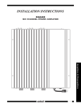
INSTALLATION INSTRUCTIONS
MODEL 780-95
“PLASMA FRIENDLY” J-BOX INFRARED RECEIVER
TABLE OF CONTENTS
Introduction...................................................................................................................................................................... 1
Features ...................................................................................................................................................................... 1
Specifications .............................................................................................................................................................. 2
Installation ....................................................................................................................................................................... 2
Placement ................................................................................................................................................................... 2
Mounting...................................................................................................................................................................... 2
Application wiring......................................................................................................................................................... 3
Advanced wiring configuration...................................................................................................................................... 3
Using the Status LED Indicator .................................................................................................................................... 4
INTRODUCTION
The 780-95 is designed to reject interference from Plasma Displays from entering the IR signal line. This IR Receiver mounts easily
into a single gang, electrical J-Box and is supplied with mounting screws and comes with a Decorator-style insert, allowing the installer
to use a Decorator-style wall cover plate. This provides an integrated look for control of A/V equipment behind closed doors or any IR
Repeater System that is in close proximity to a Plasma Display.
FEATURES
•
J-Box Mounting with Decorator-style insert (available in white(included), ivory, almond, & black)
•
4-screw terminal block for interface to Xantech Connecting Blocks
•
Works in normal 3-wire mode
•
Improved Fluorescent Light rejection
•
May be used in Direct Sunlight
•
RF Grid included for EMI reduction
•
Talk Back LED for IR reception and full system operation indication
•
Status LED for system On/Off indication (requires 12VDC Source @10mA)
•
7 units may be powered by one 781RG power supply (regulated 12VDC 200mA supply)
Note: The 780-95 will not operate in 2-wire Phantom Power mode
Page 2
Model 780-95
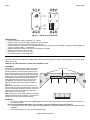
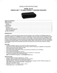
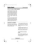
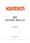
780-95
IR RECEIVER
IR Receiver
Photo Diode
®
+IR OUT
GND
Green
STATUS
LED
STATUS
+12V
Red
Talkback
LED
Figure 1 – 780-95: Front & Rear View
SPECIFICATIONS
•
Infrared modulation frequency bandwidth: 30 - 100 kHz
•
Reception range: up to 50 feet (18M), depending on local conditions
•
Reception angle: 45 degrees off axis at 50% range reduction
•
Cable requirements: 3-conductor. Use 24-gauge up to 200' (61M), 22 gauge up to 600' (180M), 20-gauge up to 2000' (600M), 18gauge up to 5000' (1.5KM) -- unshielded OK.
•
Maximum transmission length: One mile using 18-gauge wire (1.6KM)
•
Maximum current output: 100 mA (pulse)
•
Dimensions: 1-3/4” W x 4-1/8” H x 1-1/8” D
•
Power requirements: 12 volts DC @ 20mA
INSTALLATION
This unit is meant to be installed into a standard J-Box mounting box and interfaced to Xantech Connecting Blocks, such as the CB12,
789-44, 791-44, etc.
CAUTION: The J-Box must NOT be shared with 120/240VAC circuits.
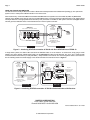
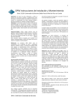
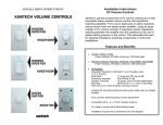
PLACEMENT
Placement of the IR Receiver does matter when used in
the presence of a Plasma Display. Ideally it should be
placed somewhere around the Display with the front of
the receiver flush with the front of (or set back from) the
Display. If the 780-95 needs to be placed in front of the
display (such as on an adjacent side wall perpendicular
to the display), make sure it is placed at a location at
least 45 degrees off axis from the corners of the unit –
see Figure 2. The presence of Direct Sunlight and
Fluorescent Lighting should not effect the reception of
this unit.
Note: Plasma interference can be reflected off of any
item it comes into contact with within approx. 3 feet from
the front of the display. Keeping this in mind, make sure
that the 780-95 is free of any obstruction that might
reflect back into the receiving eye.
Note: While this unit shows strong rejection to standard
50/60Hz ‘ballasted’ fluorescent lighting, it is still prone to
interference from CFL style Fluorescent lighting.
780-95 Top View
PLASMA DISPLAY
45°
45°
Figure 2 780-95 Placement
MOUNTING
1. Pre-wire a 3-conductor cable (refer to Specifications section for proper Wire Gauge) from the connecting block location to Jbox mounting location.
Note: If using the STATUS LED feature, use 4-conductor cable in the appropriate gauge (see Figure 5)
2. Connect proper wires to the +12VDC, GND, STATUS (if applicable), and IR OUT terminals on the rear of the 780-95 as shown
in Figure 3.
3. Secure the 780-95 into the J-Box using the supplied screws.
© 2003 Xantech Corporation
Model 780-95
Page 3
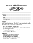
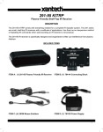
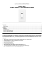
APPLICATION WIRING
A typical system, with a 780-95, 781RG Power Supply and 283M Emitters plugged into a 789-44 Connecting Block, is shown in
Figure 3:
1. Wire the appropriate leads of the 3 or 4-conductor cable from the 780-95 to the +12VDC, GND, STATUS (if applicable), and IR
IN terminals on the 789-44 Connecting Block
2. Plug in the 3.5mm mono mini plug from any of the 282, 284, 283 and 286 series Emitters into the jacks labeled EMITTERS on
the 789-44 Connecting Block and affix the opposite end to the IR Sensor Window of the controlled equipment.
3. Plug in the 2.1mm Coaxial power plug of the 781RG Power Supply (not included) into the jack labeled 12VDC on the 789-44
Connecting Block.
4. Plug the AC end of the 781RG power Supply into an ‘un-switched’ 120VAC outlet.
780-95
781RG
Plasma-Friendly
J-Box
IR Receiver
(rear view)
Satellite Receiver
Power Supply
780-95
®
IR RECEIVER
To 120 V AC
(unswitched)
IR
OUT
Connecting Block
STATUS
+12V
+12 VDC
STATUS
IR IN
®
3-Conductor
Inter-room Cable
(unshielded OK)
VCR
283M Emitter
AV Receiver
EMITTERS
789-44
GND
IR
RCVR
CONNECTING BLOCK
12VDC
Hand Held
Remote
GND
GND
+12V
283M Emitter
789-44
IR OUT
283M Blink-IR
Mouse Emitter
REMOTE ROOM
MAIN ROOM
Figure 3 - Typical System Layout using 780-95, 789-44, 781RG, and 283M Emitters
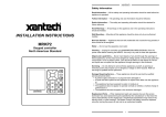
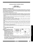
ADVANCED WIRING CONFIGURATION
780-95 may also be used in conjunction with other Xantech IR Receivers by simply wiring in parallel on a Connecting Block such as the
791-44 Amplified Block as shown in Figure 4 below.
1.
2.
Connect all IR Receivers in parallel at the terminals of the connecting block as shown in Figure 4 below.
Plug in the 2.1mm Coaxial power plug of the 781RG (or 782) Power Supply (not included) into the jack labeled PWR on the
789-44CB.
NOTE: Up to 7 IR Receivers may be connected in parallel with a single 781RG power supply. If more IR Receivers or any Keypads
are required, check total current requirements and increase power supply current rating accordingly; i.e. 782-00 - 1.2A power
Supply)
3. Plug in the Emitters 3.5mm mono mini plug (282, 284, 283 or 286 series) into the Emitter Outputs on the 791-44.
REMOTE ROOM 1
REMOTE ROOM 2
Plasma-Friendly
J-Box IR Receiver
CFL-Friendly
J-Box IR Receiver
780-95
®
STATUS
+12V
GND
+12V
7 Foot 3-Conductor
Cable with Quick
Connect Stereo
Mini Plug
IR OUT
GND
STATUS
+12V
791-44
Amplified Connecting Block
VCR
283M Emitter
IR
RCVR
490-00 Series
Micro Link
IR Receivers
3-Wire
Cable
+12V
GND
IR IN
Red
(or white)
Stripe
IR
OUT
3-Conductor
Room-toRoom Cables
(Home Runs)
791- 44
IR
OUT
S TAT U S
AMPLIFIED
CONNECTING BLOCK
GND
GND
480-00
Dinky Link
IR Receiver
12 VDC
+12V
Red
Stripe
+12 VDC
REMOTE ROOM 4
®
3-Wire
Cable
AV Receiver
EMITTERS
REMOTE ROOM 3
781RG
To 120 V AC
(unswitched)
Satellite Receiver
283M Emitter
HIGH
IR
OUT
GND
Micro Link
IR Receivers
IR RECEIVER
IR
OUT
IR OUT
490-30 Series
780-80
®
GND
IR RECEIVER
780-95
IR
OUT
+12V
MAIN ROOM, EQUIPMENT AREA, ETC.
780-80
Power Supply
283M Emitter
CD Changer
283M Emitter
Cassette DecK
283M
Blink-IR
Mouse Emitter
Figure 4 - Advanced Wiring Configuration using 780-95, 791-44, 781RG Power Supply and multiple 283M’s
CAUTION: With any of these systems, be sure the 781RG (or 782-00) Power Supply is plugged into an un-switched AC outlet. This
maintains the 780 system in "stand-by" operation so that power-on commands can be sent to the controlled equipment.
© 2003 Xantech Corporation
Page 4
Model 780-95
USING THE STATUS LED INDICATOR
The 780-95 Plasma Friendly IR Receiver includes a Status LED located just below the Talkback LED (See Fig. 1). This permits the
system to have a visible power ON/OFF indicator in the remote room.
When used with any of Xantech’s Whole-house Audio Video Entertainment systems such as the MRC-88, MRC-44 (MRC44CB1
required) or the ZPR68-10 Pre-Amp as part of the normal 4-wire hookup, connect the terminal marked STATUS on the 780-95 Plasma
Friendly IR Receiver to the appropriate Zones STATUS (or CO) connection on the MRC or ZPR system controller. See Figure 5 below.
This will give visual ON/OFF status of the associated zone on the AV System Controller.
780-95
780-95
ZPR68-10
Zone Control - IR Inputs section
®
IR RECEIVER
Plasma-Friendly
J-Box
IR Receiver
(rear view)
ZONE CONTROL - IR INPUTS
+12V
V
G
ST
S
GND
STATUS
IR IN
IR OUT
GND
STATUS
+12V
IR OUT
Hand Held
Remote
GND
STATUS
+12V
Add resistor in series
with Status line to
adjust brightness, if required.
(See Note*).
4-Conductor
Inter-room Cable
(unshielded OK)
MAIN ROOM
REMOTE ROOM
Figure 5 – Interfacing STATUS connection of 780-95 with Zone STATUS line on ZPR68-10
In Single Zone systems, the Status LED could show the ON/OFF status of an AV Receiver. To achieve this, simply plug a 12vDC
adapter, such as the Xantech 786-00 Power Supply, into the switched AC Outlet of the AV Receiver. The 12v ‘+’ and ‘-’ leads are then
connected between the STATUS (‘+’ lead) and GND (‘-’ lead) terminals of the 780-95. The Connecting Block makes a convenient tieline for extending leads of the Power Supply to the actual terminals of the 780-95 as shown in Figure 6.
781RG
780-95
IR RECEIVER
To 120 VAC
(unswitched)
283M Emitter
789-44
IR OUT
STATUS
+12 VDC
STATUS
IR IN
®
4-Conductor
Inter-room Cable
(unshielded OK)
IR
RCVR
+
283M
Emitter
EMITTERS
789-44
GND
CONNECTING BLOCK
12VDC
+12V
VCR
Connecting Block
Hand Held
Remote
GND
Add resistor in series
with Status line to
adjust brightness, if desired.
(See Note*).
Satellite Receiver
Power Supply
780-95
IR OUT
GND
STATUS
+12V
®
Plasma-Friendly
J-Box
IR Receiver
(rear view)
A/V Receiver
283M Blink-IR
Mouse Emitter
Positive Side ("+")
Plug into
Switched AC Outlet
on A/V Receiver
(see text)
786-00
Power Supply
(12V at 10 mA)
Activates STATUS
LED on 780-90 when
AV Receiver is
powered ON
MAIN ROOM
REMOTE ROOM
Figure 6 – Interfacing STATUS connection of 780-95 to Switched Outlet of AV Receiver
XANTECH CORPORATION
13100 Telfair, Sylmar CA 91342
Phone 818.362.0353 • fax 818.362.9506
Part No. 08905035 Rev A 09-14-2004
© 2003 Xantech Corporation