1
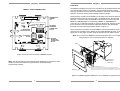
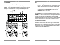
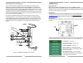
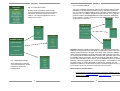
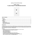
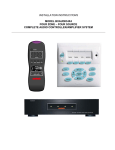
Safety Information
Read Information — All the safety and operating information should be read before the
appliance is operated.
Follow Information — All operating and use information should be followed.
Retain Information — The safety and operating information should be retained for
future reference.
Heed Warnings — All warnings on the appliance and in the operating instructions
should be heeded.
INSTALLATION INSTRUCTIONS
MRKP2
Keypad controller
North American Standard
Wall Mounting — Mounting of this appliance should be done only by an authorized
installer.
Non-Use Periods — Appliances that are left unattended and unused for long periods of
time should be de-energized.
Water — Do not use the apparatus near water.
Cleaning — Unplug the controller unit (MX88/MRC88m/MRAUDIO8x8m) from the
power outlet before cleaning the MRKP2. Use only a dry cloth to clean the apparatus.
Object and Liquid Entry — Never insert objects of any kind through the openings of
these appliances, as they may touch dangerous voltage points or short-circuit parts that
could result in a fire or electric shock. Care should be taken so that objects do not fall
and liquids are not spilled into the appliance through openings in the enclosure.
Servicing — Do not attempt to service these appliances yourself, as opening or
removing covers may expose you to dangerous voltage or other hazards. Refer all
servicing to qualified service personnel.
Damage Requiring Service — These appliances should be serviced by qualified
service personnel when:
A power supply connection or a plug has been damaged or
If liquid has been spilled into the appliance or objects have fallen into the appliance
or
The appliance has been exposed to water or moisture or
The appliance does not appear to operate normally or exhibits a marked change in
performance or
The appliance has been dropped or the enclosure damaged.
Replacement Parts — When replacement parts are required, be sure the service
technician has used replacement parts specified by the manufacturer or that have the
same characteristics as the original part. Unauthorized substitutions may result in fire,
electric shock, or other hazards. The Master Control Unit battery should be replaced
only after turning the power off and only by an authorized installer.
1
Safety Check — Upon completion of any service or repairs to this product, ask the
service technician to perform safety checks to determine that the unit is in proper
operating condition.
Lightning Storms — Unplug the controller unit (MX88/MRC88m/MRAUDIO8x8m)
during lightning storms or when unused for long periods of time.
Attachments and Accessories — Use only attachments/accessories specified by the
manufacturer.
NOTE: This equipment has been tested and found to comply with the limits for a Class B
digital device, pursuant to part 15 of the FCC Rules. These limits are designed to
provide reasonable protection against harmful interference in a residential installation.
This equipment generates, uses, and can radiate radio frequency energy and, if not installed and used in accordance with the instructions, may cause harmful interference to
radio communications. However, there is no guarantee that interference will not occur in
a particular installation.
Precautions
•
•
•
Always exercise care when operating the MRKP2 Keypad.
Do not install near any heat sources such as radiators, heat registers, stoves,
or other apparatus (including amplifiers) that produce heat.
In the unlikely event that smoke, abnormal noise, or strange odor is present,
immediately power the MRKP2 off. Please report the problem to your dealer
immediately.
Never attempt to disassemble the MRKP2. You will lose any product warranty on
the unit.
If this equipment does cause harmful interference to radio or television reception, which
can be determined by turning the equipment off and on, the user is encouraged to try to
correct the interference by one or more of the following measures:
•
Reorient or relocate the receiving antenna.
•
Increase the separation between the equipment and receiver.
•
Connect the equipment into an outlet on a circuit different from that to which the
receiver is connected.
•
Consult the dealer or an experienced radio/TV technician for help.
CAUTION: Changes or modifications not expressly approved by Xantech could void the
user’s authority to operate the equipment
Caring For the MRKP2
Clean only with a dry soft cloth.
It is important to properly care for your MRKP2 Keypad. Follow these guidelines to
ensure your device is preserved and protected.
•
Do not expose the MRKP2 to rain, liquids or moisture for an extended period of
time.
•
Do not expose the MRKP2 to temperature extremes.
Operating Temperatures & Environments
Operating Temperature: 32-104°F (0-40° C)
Humidity: 0-90%
2
3
1. Introduction
Definitions
The Xantech MRKP2 is a full-featured zone controller specifically designed for
multi-room systems based on the MX88 series, MRC88m, or MRAUDIO8x8m
multi-room controllers. It has been designed to take advantage of all major
features and capabilities of the MX88. The MRKP2 features hard buttons for
source selection, volume control, mute, and power. It is also capable of
controlling all connected sources via hard buttons, its super-bright TFT LCD
touch-screen, or its built-in IR receiver.
Zone
A Zone is defined as an area of the house that has separate source selection
capabilities from all other areas of the house. Typically, a zone is comprised of
a single room, but it is possible for a zone to spread across multiple rooms
(kitchen/dining room, master bedroom/master bath) or for multiple zones to be
contained in one room (game room/bar area or multiple zones in the yard).
The Xantech MX88 System sets a new standard in whole-house audio/video
distribution, audio amplification, and control/automation. The MX88 System
consists of the MX88 controller/amplifier, keypads or touch-panels to control
each zone, and wireless or wired web-enabled devices such as the Apple®
iPad® for controlling all zones and the entire system. When combined with IR,
RS232, or IP controlled (IP on select models only) meta-data-rich audio/video
sources and home automation components, the MX88 becomes a very capable
and self-contained system for controlling virtually everything within a
household.
Source
A Source is any audio (or audio/video) device that is connected to the MX88
source input. Any Source can be heard or viewed in any zone in the system.
MRKP2 Features
•
•
•
•
•
•
•
•
•
•
•
Fits in recommended North American standard two gang electrical
back boxes.
2.4” touch-screen 16-bit Color TFT LCD display
Displays multiple lines of meta-data and menu navigation lists
Full-featured keypad with navigation and select hard buttons.
Selectable keypad backlight color
Includes a screwless wall plate
Quick Plug and Play Installation – No PC Software Programming
Required.
Hot Swappable – no need to shut down and reset system when upon
connection of keypad
Supports Xantech QuickConfig
Built-In interference resistant (CFL, LCD, Plasma) IR receiver for
system and source control
Built-in connecting blocks for use with optional Xantech external IR
receiver and IR emitters.
MRKP2 Accessories
•
•
•
KCK2 color change kit – converts MRKP2 to black, almond, or ivory
MREM handheld remote
MRC44CB1 connecting block with 782ERGPS High Current AC
adaptor – for connecting multiple MRKP2s within a system – see
sections 2 and 3 of this manual for further details
4
5
2. System Design Overview/Applications
Important Notes
A recommended electrical back box is always required for installation of this
product (see specifications).
The MRKP2 is specifically designed to work with the MX88 series, MRC88m,
and MRAUDIO8x8m (Firmware ver. 3.16 at the time of writing this manual –
always check the Xantech web site www.xantech.com to make sure that you
are running the latest available firmware version). It is NOT designed to work
with MRC88, MRAUDIO8x8, MRC44, MRAUDIO4x4, or BXAUDIO4x4.
For the sake of simplicity, we regularly make singular references to MX88
throughout this manual. Please note that these statements apply equally to
MRC88m and MRAUDIO8x8m as well.
The MRKP2 boasts full source control capability and a super bright TFT LCD
touch-screen and its current draw is therefore slightly higher than lesser
featured keypads such as the MRKP1/1E. As a result, in installations where
long CAT5 cable runs (see specifications section) are required and/or more
than one keypad is used per zone, MRC44CB1 connecting blocks and
782ERGPS High Current AC Adaptors may be required to be installed before
the first keypad for that zone.
The MRKP2/MRKP2E and MRKP1/1E use a newer, faster keypad
communications protocol than the old MRC88KP keypad, and therefore the
MRC88KP keypads cannot be used in the same zone together with MRKP2/2E
or MRKP1/1E. The MRKP2/2E and MRKP1/1E can however be used together
in the same zone.
Planning
Before installing the MRKP2, it is essential to have a detailed and accurate
system design. The first step to a good design is to map the system. It is
advisable to mark up a copy of the house floor plan with speaker, keypad and
equipment locations, etc. Make sure that all locations are decided upon before
pre-wiring so that all necessary wiring and installation hardware is in place.
It is essential that ALL system components are accounted for prior to the prewire stage. After establishing design goals, make a detailed list of all
components. Include source equipment, keypad, expansion hubs, local source
wall plates, IR emitters, etc. Always fully test all actual components to be
installed before taking them to the jobsite. This will help streamline and
expedite any troubleshooting on site in case it becomes necessary.
6
Pre-Construction
In a pre-construction installation, walls and ceilings are open with no drywall
installed. This is desirable and allows the installer greater access than in retrofit applications. Before actually running any wire or cable, take the time to look
around each room or area of the house and plan your wire paths for maximum
efficiency. Look for routes through uncluttered parts of the stud wall or ceiling
that allow you to group all low-voltage (video, speaker wires, CAT-5, telephone,
etc.) wires wherever possible. It is a good practice to label both ends of all
cables and to protect wires by tying a plastic bag over the ends.
Note: Do not run low-voltage wires closer than 12" from high-voltage wires. If
necessary, cross low-voltage wires at a 90º angle to prevent interference.
Retro-Fit Wiring/ Post Construction
Retro-fit installations are more difficult to complete than pre-construction
because walls and ceilings are intact. Typically wires must be fished into
position through walls, floors and ceilings. Holes must be cut; speakers
mounted directly in the ceiling or walls with no electrical back- brackets and
keypads and local source wall plates must be mounted in existing drywall.
Pre-Wiring
Wiring between MX88 and MRKP2E
The MX88 and all associated components are wired using CAT-5, CAT-5e,
CAT-6, or CAT-7 cable terminated to the T568A or T568B Wiring Standard
(Figure 2.1). Please note that all references made throughout this manual to
CAT-5 apply to CAT-5e, CAT-6, and CAT-7 as well. When pre-wiring the
system, run lengths of CAT-5 from the pre-determined MRC88m location to
each Keypad or Touch Panel location. The CAT-5 cable routes all Power,
Control, Communication, and IR information needed for full system operation.
Important: While there are two wiring standards, it is very important to be
consistent to one configuration throughout the entire system. Otherwise, the
system will not operate.
Speaker Wiring from MX88 to each zone
Speaker wiring will need to be separately routed from the MX88 to each zone.
7
MRKP2 – FRONT PANEL
NAVIGATION BUTTONS
UP, DOWN, LEFT, RIGHT,
ENTER/SELECT (center button)
POWER
ON/OFF
INTERNAL IR
SENSOR
MAIN
DISPLAY
“X” (SETUP)
SCAN
FWD/RRW
scan
volume
VOLUME
UP/DN
skip
TRACK SKIP
NEXT/PREV
MUTE
Figure 2.1: T568A and T568B Wiring Standard
PLAY
RJ45 Connector at
Controller/Amplifier
Cat 5
Cable
Wire Color
white/orange
orange
white/green
blue
white/blue
green
white/brown
brown
Pin #
1
2
3
4
5
6
7
8
PAUSE
Signal
485 +
485 12V RET
IR RET
IR
+12V
Attn. 485
IR Loop Back
STOP
Figure 2.3: MRKP2 Keypad layout and Main display
Notes:
RJ45 Connector
at Keypad
Wire Color
white/orange
orange
white/green
blue
white/blue
green
white/brown
brown
Pin #
1
2
3
4
5
6
7
8
Signal
485 +
485 12V RET
IR RET
IR
+12V
Attn. 485
IR Loop Back
•
Tone Control functions of the MRKP2 can be entered by pressing the
Next arrow once inside a source control page. Please note that each of
the three controls can be returned to their center position by tapping
the center of each bar.
•
Unlike older keypads, and due to the unique and streamlined functional
set-up of the MRKP2E’s buttons, “press-and-hold” tier 2 functions are
not supported. However, Tier 2 button IDs and the macros underneath
them are available through Universal Dragon.
Figure 2.2: MX88 – MRKP2 Pin-out diagram for Cat-5 cable
(T568B configuration)
8
9
Installation
The MRKP2 is designed to mount in a standard two gang electrical back-box
(see Specifications sections for details). Typical mounting height is 56-60
inches (1.53 meters) from the floor to the bottom of the frame. This provides
optimum “eye-level” viewing for the largest number of people.
MRKP2 – REAR CONNECTORS
XANTECHCORP.
MRKP2- 050710000077
IR IN
STATUS
GND
JP1
TERMINATION
+12V
SENSOR
ENABLE
JP3
TERMINATION
JUMPER
JP1
TO EXPANSION
KEYPAD
CONNECT TO
CONTROLLER
PORT ON
OTHER KEYPAD
TO MRC88m/MX88
CONTROLLER PORT
IR GND
OUT
EXTERNAL
IR SENSOR
CONNECTING
BLOCK
IN-ZONE
IR EMITTER
CONNECTING
BLOCK
Route the CAT-5 cable from the MX88 into the back of the electrical back-box,
terminate it with an RJ-45 connector after it is passed through the electrical
back-box. Connect it to the appropriate RJ-45 connector on the rear of the
MRKP2 (“CONTROLLER” for connecting to MX88, or “EXPANSION” if
connecting to an extension keypad). If using an IR Receiver, strip the ends of
three conductors of the IR receiver’s cable and insert into the appropriate
terminals of the IR Input terminal block shown in Figure 3.1.
Once connections are made, mount the MRKP2 into the electrical back-box
using the two provided screws. Mount the Trim Plate Bracket as shown in the
Figure 2.5 on next page, and then snap the Screw-less Trim Plate in place.
Note: Do not mount the MRKP2 in the same electrical back- box as high
voltage devices such as electrical outlets or switches.
MRKP2
Figure 2.4: Rear connector board of MRKP2 Keypad
TWO-GANG
DOUBLE
GANG
WALL
BOX
ELECTRICAL
Note: The IR Out feature on this keypad comes disabled from the factory and if
needed, it should be enabled using the Xantech Universal Dragon
programming software.
BACK-BOX
TRIM PLATE
M OUNTING SCREWS (6-32 x ¾”)
Not e: M oun t ing screw s are includ ed w it h m ost elect rical b ack-b oxes.
Ext ra m o unt ing screw s are also includ ed w it h t he M RKP2 p ro d u ct in case
t h e b ack-b ox screw s are not su p p lied or are som eho w not suit ab le fo r use.
Figure 2.5: MRKP2 keypad installation in U.S. standard two gang back-box
10
11
Note:
3. Connections
MRKP2 to MX88 and Expansion Keypads
Each RJ-45 connector under each PREAMP OUT (1 – 8) is considered a “Zone
port”. This Zone port interfaces with MRKP2 Keypad through CAT-5 cables.
These connectors carry command/control information between the keypad and
the MX88. Connect CAT-5 cables terminated to an RJ-45 connector from each
Keypad to the corresponding RJ45 connector of the MX88 as shown below.
(See Specifications section for maximum length of Cat-5 cables)
Zone 4
IR emitter
Zone 1
IR emitter
1. There are four keypads maximum per zone. Remove termination
jumper on all keypads except for the last keypad (see location of JP1
on Fig 2.4). Each expansion keypad must each have its own unique
address. (see Installer Settings menu on Section 4 of this manual).
2. Long CAT5 cable runs and/or the use of more than one keypad per
zone will require the use of MRC44CB1 and 782ERGPS High Current
AC adaptors. Please see Important Notes on page 6 and the
Specifications page for more details.
Internal IR Receiver
The internal IR receiver is located beneath the keypad’s face plate between the
POWER and “X” buttons (see Figure 2.3). The internal IR receiver receives IR
commands for the MRKP2 and for the MX88. It will also pass-thru IR remote
control commands to audio sources, via an emitter, to each of the sources
connected to the MX88. The internal IR receiver is interference friendly.
However, some optically noisy environments may require the use of an external
IR receiver. (See Figure 3.1 for details on using an external IR receiver)
Compatible Handheld remotes
MRC88m Rear
Zone 1
Zone 2
XANTECH COR P.
MRKP2 - 050710000077
Zone 8
XANTECH COR P.
MRKP2 - 050710000077
XANTECH COR P.
MRKP2 - 050710000077
MAIN
KEYPADS
The MRKP2’s can be controlled with a Xantech handheld remote controller,
such as a Xantech RC68 or MREM is for accessing control functions of the
source such as navigation, menu, and transport controls. Other programmable
Xantech remotes such as XTR39 can also be used. The list of RC68 codes is
available at www.xantech.com/Controls/KeypadsRemotes/Remotes/MREM, in
the Products page, under “MREM Code List”.
Note: RC68 commands may not be used with projects created in QuickConfig.
MRC44CB1
+
782ERGPS
MRC44CB1
+
782ERGPS
MRKP2 Rear
XANTECH COR P.
MRKP2 - 050710000077
MRC44CB1
+
782ERGPS
MRKP2 Rear
MRKP2 Rear
XANTECH COR P.
MRK P2 - 050710000077
XANTECH COR P.
MRKP2 - 050710000077
EXTENSION
KEYPADS
Figure 3.0: MRKP2 to MX88 with expansion keypads
12
13
External IR Receiver Connections
4. MRKP2 Setup
Use an external Xantech IR Receiver in cases where a hand-held remote
needs to be pointed somewhere other than at the MRKP2 or in cases where
additional interference requires the use of a different type of IR receiver or IR
receiver mounting location. Typical IR Receiver locations are near a TV or other
equipment such as a Local Source (DVD Player, A/V Receiver,…etc.). A CAT5 cable can be used to extend the IR receiver’s wire, if necessary. Refer to the
bottom of the Specifications section (page 19) for wiring instruction when using
CAT-5 cable to extend the IR signal.
Initial Power-up
Whenever the MX88 or the keypad itself is reset, the MRKP2 will take
approximately 1 minute to initialize. During most of this period of time, with the
exception of first 5 seconds, the On/Standby LED will be illuminated in green as
an indication that boot-up is in progress.
By default, the MRKP2 External and Internal IR receivers are both active.
Having both active, in some cases, can cause issues with IR signal reflection
and/or multiple processing of the same IR command. In such specific cases it
is advisable to disable the Internal IR when using an external IR receiver. The
internal IR receiver can be disabled by removing jumper clip JP3 as shown
below.
QuickConfig
The Xantech QuickConfig feature facilitates the setup of the MX88 system from
a keypad without the use of a PC. Please refer to the QuickConfig Guide at
www.xamtech.com/MX88 for details on setting up QuickConfig.
Set-up menu
To access the Main Setup Menu, press and hold down the “X” key for at least 5
seconds.
Reset
button
IRIN
GND
IRSENSOR
ENABLEJUMPER
(JP3)
+12VDC
XANTECH
IRRECEIVER
XANTECH C
ORP.
MRKP2 - 050710000077
TO MRC88m
CONTROLLER
Once the Main Setup Menu is displayed on the touch screen simply touch and
release the listed item to access more information or to make adjustments.
TO EXPANSION
KEYPAD
Information - See Fig. 4.1
Installer Settings – See Fig. 4.3
GND
IROUT
Backlight Settings – See Fig. 4.2
IN-ZONEIR
EMITTER
Figure 3.1: MRKP2 to External IR Connections
14
Save and Exit - Leave the Main Setup
Menu and go back to normal display mode
and save changes
Exit without Saving - Leave the Main
Setup Menu and go back to normal display
mode without saving changes
15
Fig. 4.3 Installer Settings
Fig. 4.1 Information screen
Displays basic information about the unit.
Press and release items on the list to display
information about the unit and its current
settings. No changes/adjustments can be
made on this screen.
This menu facilitates adjustments that may be necessary during system
installation, and should be accessed by factory authorized personnel
only. To enter the Installer Settings menu, highlight “Installer Settings” by
using the “UP” or “DOWN” navigation buttons (see Fig. 2.3 on page 9),
press and release the ENTER/SELECT button so that the “Restricted”
screen appears, and then press and hold the “ENTER/SELECT” button
for longer than 5 seconds.
+
Important: While in Installer Settings menu, if “App Upgrade” is accidently
selected, the keypad will enter and remain in application update mode, and will
display “Please Restart The Keypad”. To exit this mode, press the “RESET”
button behind the MRKP2 trim panel with a blunt object (see figure on page
15). The keypad will reboot and display “Please Load Application Files”. Press
the “RESET” button once again. This will conclude the application update
process without installing new firmware, and the MRKP2 will return to normal
operation. After the keypad returns to normal operation, it is advisable to reset
the entire system by turning the MX88 off and back on. Please note that
application update is to be performed by factory authorized personnel only, and
the procedure to do so is not within the scope of this document.
Fig. 4.2 Backlight Settings
Allow adjustments of Button
colors and brightness, Screen
brightness, and Screen
backlight timer.
Other reference documentation
•
•
16
Universal Dragon MX88 programming Instructions: MRKP2 and 2E:
Download from www.xantech.com, under MRKP2 or MRKP2E
QuickConfig Guide: Download from www.xantech.com, under MX88 or
MRC88m
17
5. Troubleshooting
Symptom
6. Specifications
Possible Cause
1. RJ-45 plug crimped
incorrectly; or wiring pinout of RJ-45 reversed.
MRKP2 does not power
up or resets itself
randomly
2. Break or intermittent
connection in CAT-5
between Zone and “HeadEnd”.
3. CAT5 cable length
exceeds specification, or
more than one keypad is
used in a zone.
The Next button on
touchscreen or any
other virtual button in
top right corner of the
screen is not
operational
Protect switch on
MX88/MRC88m is left in
Off position. Protect Off
setting is only to be used
during the QuickConfig
setup.
1. Wiring: Incorrect wiring
between MRKP2 and
MRC88m.
No control of IR
sources
2. IR emitter defective at
source.
3. IR Enable jumper is set
incorrectly
Intermittent IR source
control
Solution
Verify wiring pin-out and RJ45 crimp. Correct by recrimping RJ-45 to CAT-5
cable.
Check RJ-45 to RJ-45
connections with cable tester
or voltmeter. +12V terminal
on back of MRKP2 should
read +9V DC or higher with
the keypad on.
Use MRC44CB1 and
782ERGPS 12V High Current
AC Adaptor at keypad side,
prior to the first keypad.
Return the Protect switch to
On position and reset the
MX88/MRC88m system
Verify and correct wiring.
18
Front panel dimensions
4-1/2” (114mm) wide x 4-5/8” (117mm) high x 1/4”
(6mm) deep
Wall cutout
Depends on electrical back-box used – see below
2-1/4” (57mm) for unit and wiring – actual
Mounting depth
Max length Cat-5
Cable* with 1 keypad
per zone
Max length Cat-5
cable* with 1 keypad
and 1, 2, or 3
expansion keypads
Operating Temperature
& Humidity
mounting depth will depend on electrical back-box
used
250 feet (75 meters) total per zone* If this
distance is exceeded, a MRC44CB1 and
782ERGPS should be placed right before the
keypad.
Must use MRC44CB1 connecting block and
782ERGPS 12V High Current AC adaptor at
and before the first keypad. After the first
keypad, each time a cable run exceeds 250
feet (75 meters) total, another MRC44CB1
and 782ERGPS will need to be added before
the next keypad.
32-104°F (0-40° C)
0-90% Relative Humidity
Replace IR emitter.
Compatible Electrical back-boxes
Make sure IR Sensor Enable
jumper is properly configured.
(See Section 3 and Figure
3.1)
Check to see if ambient light
is shining on built in IR
receiver or in direct line with
plasma TV noise. If the IR
emitter is flashing when IR is
not being sent, IR flooding is
likely cause. Disable the builtin IR Receiver. Consider use
of an external IR Receiver
(see Fig 2.2 and 3.2).
IR flooding
MRKP2 basic dimensions and cable lengths
North American
standard two gang
electrical back boxes
Carlon® BH235A, B232A-UPC, B225R-UPC,
or BH234R
* CAT5/5e/6/7 may be used. Cable quality may reduce this maximum length.
Extending external IR receiver
connection with 3-wire cable
Maximum allowable
Size (AWG)
length (feet)
24
150
22
300
20
1000
18
2000
19
Extending external IR
receiver connection
with Cat-5 cable using all 8
conductors
Use 4 striped wires for GND
Use 2 solid wires for IR signal
Use 2 solid wires for +12V
20
21
Xantech Limited Warranty
Xantech LLC (“Xantech”) warrants this product to be free defects in materials
and workmanship for a period of two years from the date of documented
purchase by the original consumer. Any products returned to Xantech and
found to be defective by Xantech within the warranty period will be repaired or
replaced, at Xantech’s option, at no charge. Xantech will not be responsible for
the actual cost of the installation or removal of the product, nor for any
incidental or consequential damages. Some states do not allow the exclusion
or limitation of incidental or consequential damages, so the above limitation
may not apply to you. This warranty gives you specific legal rights. You may
have additional legal rights that vary from state to state.
Xantech® is a registered trademark of Xantech LLC
Carlon® is a registered trademark of Thomas & Betts Corporation
Apple® and iPad® are registered trademarks of Apple Inc.
All other trademarks are the properties of their registered owners.
Xantech LLC
13100 Telfair Avenue, Sylmar CA 91342 | Xantech.com
Installation Instructions, MRKP2 © 2010 Xantech LLC
Document #08905262B
This document is copyright protected. No part of this manual may be copied or
reproduced in any form without prior written consent from Xantech LLC. Xantech LLC
shall not be liable for operational, technical, or editorial errors/omissions made in this
document.
22
23