1
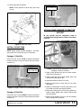
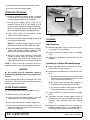
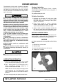
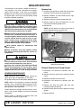
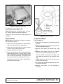
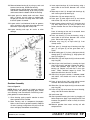
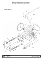
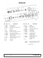
(Rev. 2/16/2007) MAN0155 SG100 Tested. Proven. Unbeatable. OPERATOR'S MANUAL STUMP GRINDER TO THE DEALER: Assembly and proper installation of this product is the responsibility of the Woods® dealer. Read manual instructions and safety rules. Make sure all items on the Dealer’s Pre-Delivery and Delivery Check Lists in the Operator’s Manual are completed before releasing equipment to the owner. The dealer must complete the Product Registration included with the Operator’s Manual. The customer must sign the registration which certifies that all Dealer Check List items have been completed. The dealer is to return the prepaid postage portion to Woods, give one copy to the customer, and retain one copy. Failure to complete and return this card does not diminish customer’s warranty rights. TO THE OWNER: Read this manual before operating your Woods equipment. The information presented will prepare you to do a better and safer job. Keep this manual handy for ready reference. Require all operators to read this manual carefully and become acquainted with all adjustment and operating procedures before attempting to operate. Replacement manuals can be obtained from your dealer. To locate your nearest dealer, check the Dealer Locator at www.WoodsEquipment.com, or in the United States and Canada call 1-800-319-6637. The equipment you have purchased has been carefully engineered and manufactured to provide dependable and satisfactory use. Like all mechanical products, it will require cleaning and upkeep. Lubricate the unit as specified. Observe all safety information in this manual and safety decals on the equipment. For service, your authorized Woods dealer has trained mechanics, genuine Woods service parts, and the necessary tools and equipment to handle all your needs. Use only genuine Woods service parts. Substitute parts will void the warranty and may not meet standards required for safe and satisfactory operation. Record the model number and serial number of your equipment in the spaces provided: Model: _______________________________ Date of Purchase: _____________________ Serial Number: (see Safety Decal section for location) ____________________________________ Provide this information to your dealer to obtain correct repair parts. Throughout this manual, the term IMPORTANT is used to indicate that failure to observe can cause damage to equipment. The terms CAUTION, WARNING, and DANGER are used in conjunction with the Safety-Alert Symbol (a triangle with an exclamation mark) to indicate the degree of hazard for items of personal safety. This Safety-Alert Symbol indicates a hazard and means ATTENTION! BECOME ALERT! YOUR SAFETY IS INVOLVED! DANGER Indicates an imminently hazardous situation that, if not avoided, will result in death or serious injury. WARNING Indicates a potentially hazardous situation that, if not avoided, could result in death or serious injury, and includes hazards that are exposed when guards are removed. CAUTION IMPORTANT or NOTICE NOTE Indicates a potentially hazardous situation that, if not avoided, may result in minor or moderate injury. Indicates that failure to observe can cause damage to equipment. Indicates helpful information. 2 Introduction Gen’l (Rev. 2/5/2007) TABLE OF CONTENTS INTRODUCTION . . . . . . . . . . . . . . . . . . . . . . . . . . . . . . . . . . . . . . . . . . . . . . 2 SPECIFICATIONS . . . . . . . . . . . . . . . . . . . . . . . . . . . . . . . . . . . . . . . . . . . . . 4 GENERAL INFORMATION . . . . . . . . . . . . . . . . . . . . . . . . . . . . . . . . . . . . . . 4 SAFETY RULES . . . . . . . . . . . . . . . . . . . . . . . . . . . . . . . . . . . . . . . . . . . . 5 - 7 SAFETY DECALS . . . . . . . . . . . . . . . . . . . . . . . . . . . . . . . . . . . . . . . . . . . 8 - 9 OPERATION . . . . . . . . . . . . . . . . . . . . . . . . . . . . . . . . . . . . . . . . . . . . . . . . 10 OWNER SERVICE . . . . . . . . . . . . . . . . . . . . . . . . . . . . . . . . . . . . . . . . . . . 14 DEALER SERVICE . . . . . . . . . . . . . . . . . . . . . . . . . . . . . . . . . . . . . . . . . . . 16 DEALER CHECK LISTS . . . . . . . . . . . . . . . . . . . . . . . . . . . . . . . . . . . . . . . 23 PARTS STUMP GRINDER ASSEMBLY . . . . . . . . . . . . . . . . . . . . . . . . . . . . . . 24 STUMP GRINDER PARTS LIST. . . . . . . . . . . . . . . . . . . . . . . . . . . . . . 25 GEARBOX ASSEMBLY AND PARTS LIST . . . . . . . . . . . . . . . . . . . . . 26 DRIVELINE ASSEMBLY AND PARTS LIST. . . . . . . . . . . . . . . . . . . . . 27 BOLT TORQUE CHART . . . . . . . . . . . . . . . . . . . . . . . . . . . . . . . . . . . . . . . 28 BOLT SIZE CHART & ABBREVIATIONS . . . . . . . . . . . . . . . . . . . . . . . . . . 29 PARTS WARRANTY . . . . . . . . . . . . . . . . . . . . . . . . . . . . . . . . . . . . . . . . . . 30 PRODUCT WARRANTY . . . . . . . . . . . . . . . . . . . . . . . INSIDE BACK COVER MAN0155 (Rev.2/16/2007) Introduction 3 SG100 SPECIFICATIONS Weight . . . . . . . . . . . . . . . . . . . . . . . . . . . . . . . . . . . . . . . . . . . . . . . . . . . . . . . . . . . . . 1012 lbs. Cutting wheel diameter . . . . . . . . . . . . . . . . . . . . . . . . . . . . . . . . . . . . . . . . . . . . . . . . 34 inches Cutting wheel speed . . . . . . . . . . . . . . . . . . . . . . . . . . . . . . . . . . . . . . . . . . . . . . . . . . . 895 rpm Cutting arc. . . . . . . . . . . . . . . . . . . . . . . . . . . . . . . . . . . . . . . . . . . . . . . . . . . . . . . . .55 degrees Hub torque . . . . . . . . . . . . . . . . . . . . . . . . . . . . . . . . . . . . . . . . . . . . . . . . . . . . . . . . . 450 lbs-ft. Required horsepower . . . . . . . . . . . . . . . . . . . . . . . . . . . . . . . . . . . . . . . . . . . . . . 35 to 100 HP Cutting teeth . . . . . . . . . . . . . . . . . . . . . . . . . . . . . . . . . . . . . . . . . . . . . . .25 carbide steel teeth Maximum stump height . . . . . . . . . . . . . . . . . . . . . . . . . . . . . . . . . . . . . . . . . . . . . . . . 24 inches Maximum cutting depth . . . . . . . . . . . . . . . . . . . . . . . . . . . . . . . . . . . . . . . . . . . . . . . . 12 inches GENERAL INFORMATION The purpose of this manual is to assist you in operating and maintaining your stump grinder. Read it carefully. It furnishes information and instructions that will help you achieve years of dependable performance. These instructions have been compiled from extensive field experience and engineering data. Some information may be general in nature due to unknown and varying operating conditions. However, through experience and these instructions, you should be able to develop procedures suitable to your particular situation. The illustrations and data used in this manual were current at the time of printing but, due to possible inline production changes, your machine may vary slightly in detail. We reserve the right to redesign and change the machines as may be necessary without notification. Throughout this manual, references are made to right and left directions. These are determined from the operator’s position in the tractor seat. 4 Introduction MAN0155 (Rev. 2/16/2007) SAFETY RULES ATTENTION! BECOME ALERT! YOUR SAFETY IS INVOLVED! Safety is a primary concern in the design and manufacture of our products. Unfortunately, our efforts to provide safe equipment can be wiped out by an operator’s single careless act. In addition to the design and configuration of equipment, hazard control and accident prevention are dependent upon the awareness, concern, judgement, and proper training of personnel involved in the operation, transport, maintenance, and storage of equipment. It has been said, “The best safety device is an informed, careful operator.” We ask you to be that kind of operator. TRAINING Safety instructions are important! Read all attachment and power unit manuals; follow all safety rules and safety decal information. (Replacement manuals and safety decals are available from your dealer. To locate your nearest dealer, check the Dealer Locator at www.WoodsEquipment.com, or in the United States and Canada call 1-800-3196637.) Failure to follow instructions or safety rules can result in serious injury or death. If you do not understand any part of this manual and need assistance, see your dealer. Know your controls and how to stop engine and attachment quickly in an emergency. Operators must be instructed in and be capable of the safe operation of the equipment, its attachments, and all controls. Do not allow anyone to operate this equipment without proper instructions. Keep hands and body away from pressurized lines. Use paper or cardboard, not hands or other body parts to check for leaks. Wear safety goggles. Hydraulic fluid under pressure can easily penetrate skin and will cause serious injury or death. Make sure that all operating and service personnel know that if hydraulic fluid penetrates skin, it must be surgically removed as soon as possible by a doctor familiar with this form of injury or gangrene, serious injury, or death will result. CONTACT A P HYS ICIA N IM ME DIATE LY IF FLU ID ENTERS SKIN OR EYES. DO NOT DELAY. SG100 Safety Rules (Rev. 6/16/2006) PREPARATION Check that all hardware is properly installed. Always tighten to torque chart specifications unless instructed otherwise in this manual. Always wear relatively tight and belted clothing to avoid getting caught in moving parts. Wear sturdy, rough-soled work shoes and protective equipment for eyes, hair, hands, hearing, and head; and respirator or filter mask where appropriate. Make sure attachment is properly secured, adjusted, and in good operating condition. Power unit must be equipped with ROPS or ROPS cab and seat belt. Keep seat belt securely fastened. Falling off power unit can result in death from being run over or crushed. Keep foldable ROPS system in “locked up” position at all times. Make sure all safety decals are installed. Replace if damaged. (See Safety Decals section for location.) Make sure shields and guards are properly installed and in good condition. Replace if damaged. OPERATION Do not allow bystanders in the area when operating, attaching, removing, assembling, or servicing equipment. Consult local utilities before working. Know location of all underground cables, pipelines, overhead wires, and other hazards in working area and avoid contact. Do not put stump grinder into service unless all shields and guards are in place and in good condition. Replace if damaged. Keep bystanders away from equipment. Do not operate or transport equipment while under the influence of alcohol or drugs. Operate only in daylight or good artificial light. (Safety Rules continued on next page) Safety 5 SAFETY RULES ATTENTION! BECOME ALERT! YOUR SAFETY IS INVOLVED! (Safety Rules continued from previous page) Avoid contact with electrical wires. Keep hands, feet, hair, and clothing away from equipment while engine is running. Stay clear of all moving parts. Always comply with all state and local lighting and marking requirements. Never allow riders on power unit or attachment. Power unit must be equipped with ROPS or ROPS cab and seat belt. Keep seat belt securely fastened. Falling off power unit can result in death from being run over or crushed. Keep foldable ROPS system in “locked up” position at all times. tions or have service performed by a qualified dealer. TRANSPORTATION A minimum 20% of tractor and equipment weight must be on the tractor front wheels when attachments are in transport position. Without this weight, tractor could tip over, causing personal injury or death. The weight may be attained with a loader, front wheel weights, ballast in tires or front tractor weights. Weigh the tractor and equipment. Do not estimate. Reduce transport speed to avoid bouncing and brief loss of steering control. Always sit in power unit seat when operating controls or starting engine. Securely fasten seat belt, place transmission in neutral, engage brake, and ensure all other controls are disengaged before starting power unit engine. Always comply with all state and local lighting and marking requirements. Shift tractor transmission into park or neutral and set brakes before engaging PTO and grinding. Do not operate or transport on steep slopes. Never allow riders on power unit or attachment. Turn off power to unit before transporting. Do not operate PTO during transport. Do not operate or transport equipment while under the influence of alcohol or drugs. Do not operate auxiliary hydraulics during transport. MAINTENANCE Look down and to the rear and make sure area is clear before operating in reverse. Use extreme care when working close to fences, ditches, other obstructions, or on hillsides. Do not operate or transport on steep slopes. Do not stop, start, or change directions suddenly on slopes. Use extreme care and reduce ground speed on slopes and rough terrain. Before performing any service or maintenance, lower equipment to ground or block securely, turn off engine, remove key, and disconnect driveline from tractor PTO. NEVER GO UNDERNEATH EQUIPMENT. Never place any part of the body underneath equipment or between moveable parts even when the engine has been turned off. Hydraulic system leak-down, hydraulic system failures, mechanical failures, or movement of control levers can cause equipment to drop or rotate unexpectedly and cause severe injury or death. • Service work does not require going underneath. • Read Operator's Manual for service instruc- 6 Safety Service and maintenance work not covered in OWNER SERVICE must be done by a qualified dealership. Special skills, tools, and safety procedures may be required. Failure to follow these instructions can result in serious injury or death. Before performing any service or maintenance, lower equipment to ground or block securely, turn off engine, remove key, and disconnect driveline from tractor PTO. Do not modify or alter or permit anyone else to modify or alter the equipment or any of its components in any way. Always wear relatively tight and belted clothing to avoid getting caught in moving parts. Wear sturdy, rough-soled work shoes and protective equipment for eyes, hair, hands, hearing, and head; and respirator or filter mask where appropriate. Do not allow bystanders in the area when operating, attaching, removing, assembling, or servicing equipment. Make sure attachment is properly secured, adjusted, and in good operating condition. Never perform service or maintenance with engine running. SG100 Safety Rules (Rev. 6/16/2006) SAFETY RULES ATTENTION! BECOME ALERT! YOUR SAFETY IS INVOLVED! Keep all persons away from operator control area while performing adjustments, service, or maintenance. Tighten all bolts, nuts, and screws to torque chart specifications. Check that all cotter pins are installed securely to ensure equipment is in a safe condition before putting unit into service. Make sure shields and guards are properly installed and in good condition. Replace if damaged. When lubricating telescoping PTO drives, keep fingers out of shield access slots to prevent injury. STORAGE Block equipment securely for storage. Do not climb or lean on equipment stored on stand. Keep children and bystanders away from storage area. SG100 Safety Rules (Rev. 6/16/2006) Safety 7 SAFETY & INSTRUCTIONAL DECALS ATTENTION! BECOME ALERT! YOUR SAFETY IS INVOLVED! Replace Immediately If Damaged! 1 - PN MS-503 10 11 1 2 5 2 - PN MS501-A 3 Under Shield 9 Under Shield 7 6 3 - PN MS-505 1 2 5 3 Under Shield 7 4 - PN MS-502-A Early Production Only 8 Safety SG100 Safety Rules (Rev.2/16/2007) SAFETY & INSTRUCTIONAL DECALS ATTENTION! BECOME ALERT! YOUR SAFETY IS INVOLVED! Replace Immediately If Damaged! 5 - PN - MS-171 6 - 18866 WARNING DO NOT EXCEED PTO SPEED OF 540 RPM PTO speeds higher than 540 RPM can cause equipment failure and personal injury. 18866-D 7 - PN 102941 9 - PN33347 WARNING 10 - PN 18864 DANGER CRUSHING AND PINCHING HAZARD Be extremely careful handling various parts of the machine. They are heavy and hands, fingers, feet, and other body parts could be crushed or pinched between tractor and implement. Operate tractor controls from tractor seat only. Do not stand between tractor and implement when tractor is in gear. Make sure parking brake is engaged before going between tractor and implement. Stand clear of machine while in operation or when it is being raised or lowered. FAILURE TO FOLLOW THESE INSTRUCTIONS COULD RESULT IN SERIOUS INJURY OR DEATH. 1002941-A DANGER ROTATING DRIVELINE GUARD MISSING. DO NOT OPERATE. DANGER GUARD MISSING. DO NOT OPERATE. 33347E DANGER CONTACT CAN CAUSE DEATH KEEP AWAY! DO NOT OPERATE WITHOUT All driveline guards, tractor and equipment shields in place Drivelines securely attached at both ends Driveline guards that turn freely on driveline 18864-C 11 - Serial Number Plate MODEL NO. SERIAL NO. Woods Equipment Company Oregon, Illinois, U.S.A. BE CAREFUL! Use a clean, damp cloth to clean safety decals. Avoid spraying too close to decals when using a pressure washer; high-pressure water can enter through very small scratches or under edges of decals causing them to peel or come off. Replacement safety decals can be ordered free from your Woods dealer. To locate your nearest dealer, check the Dealer Locator at www.WoodsEquipment.com, or in the United States and Canada call 1-800-319-6637. SG100 Safety Rules (Rev. 2/16/2007) Safety 9 OPERATION The operator is responsible for the safe operation of this stump grinder. The operator must be properly trained. Operators should be familiar with the tractor, stump grinder, and all safety practices before starting operation. Read the safety rules and safety decals on page 5 through page 9. WARNING Do not allow bystanders in the area when operating, attaching, removing, assembling, or servicing equipment. Make sure attachment is properly secured, adjusted, and in good operating condition. Do not put digger into service unless all shields and guards are in place and in good condition. Replace if damaged. CAUTION Always wear relatively tight and belted clothing to avoid getting caught in moving parts. Wear sturdy, rough-soled work shoes and protective equipment for eyes, hair, hands, hearing, and head; and respirator or filter mask where appropriate. TRACTOR STABILITY WARNING Figure 1. 100 ft. Hazard Zone Keep bystanders away from equipment. A minimum 20% of tractor and equipment weight must be on the tractor front wheels when attachments are in transport position. Without this weight, tractor could tip over, causing personal injury or death. The weight may be attained with a loader, front wheel weights, ballast in tires or front tractor weights. Weigh the tractor and equipment. Do not estimate. Keep hands and body away from pressurized lines. Use paper or cardboard, not hands or other body parts to check for leaks. Wear safety goggles. Hydraulic fluid under pressure can easily penetrate skin and will cause serious injury or death. Make sure that all operating and service personnel know that if hydraulic fluid penetrates skin, it must be surgically removed as soon as possible by a doctor familiar with this form of injury or gangrene, serious injury, or death will result. CONTACT A PH YS ICIA N IM ME DIATE LY IF FLU ID ENTERS SKIN OR EYES. DO NOT DELAY. STUMP GRINDER PRE-OPERATION Make sure spring-activated locking pin or collar slides freely and is seated firmly in tractor PTO spline groove. NOTE: For operation of this stump grinder, references to right, left, forward, and rearward directions are determined from the operator’s position in the tractor seat. Know your controls and how to stop engine and attachment quickly in an emergency. NOTICE Operators must be instructed in and be capable of the safe operation of the equipment, its attachments, and all controls. Do not allow anyone to operate this equipment without proper instructions. Never allow children or untrained persons to operate equipment. 10 Operation Figure 2. Tractor Stability ■ Gearbox does not contain oil. Fill before operating. 1. Fill gearbox with 6 pints of SAE 90 oil. 2. Grease both fittings on the swivel assembly as shown in Figure 4. 3. Grease U-joints on end of driveline as shown. MAN0155 (Rev. 2/16/2007) 4. Grease slip joint on driveline. NOTE: Check gearbox oil level daily after initial start up. CAT 2 Hitch Pin DP7 Figure 5. Category 2 Hitch Pin Installed (Right Side) ATTACH STUMP GRINDER TO TRACTOR NOTICE ■ Top cylinder must be completely raised to avoid driveline damage before raising 3-point lower lift arms. Figure 3. Lubrication Points INSTALL 3-POINT PINS NOTE: Stump grinder includes Category 1 and Category 2 hitch pins. Install hitch pins as instructed. Category 1 Hitch Pin Install hitch pin on the inside of 3-point attachment bracket as shown in Figure 4. Secure with lock washer and hex nut. DP5 CAT 1 Hitch Pin Figure 6. Stump Grinder Attached to Tractor (Category 1 Hitch Pins Shown) 1. Attach stump grinder hitch pins to tractor 3-point lower lift arm and secure. 2. Attach tractor top link to stump grinder clevis and secure with tractor top link pin. 3. Connect driveline to tractor PTO shaft. DP6 Figure 4. Category 1 Hitch Pin Installed (Right Side) Category 2 Hitch Pin Install hitch pin on the outside of 3-point attachment bracket as shown in Figure 5. Secure with lock washer and hex nut. MAN0155 (Rev. 2/16/2007) 4. Slide slip collar back or push slip pin in to make connection. 5. Make sure connection is secure. Slip collar or slip pin should snap back into original position. 6. Adjust the tractor 3-point arm anti-sway devices to prevent stump grinder from swaying side-to-side during transport. 7. Adjust tractor drawbar so that it will not interfere with stump grinder or driveline. Operation 11 8. Attach quick couplers to tractor hydraulic source. 9. Place jack stand in storage position. OPERATING TECHNIQUE 1. Power for operating the stump grinder is supplied by the tractor PTO. Know how to stop the tractor and stump grinder quickly in an emergency. LYNCH PIN 2. Position stump grinder above stump to be removed. Engage PTO at low engine rpm to minimize stress on the drive system and gearbox. With PTO engaged, increase PTO speed to 540 rpm and maintain throughout grinding operation. DP1 3. Lower tractor 3-point arm until pads on stump grinder are firmly on the ground. 4. Activate top cylinder to lower the cutting wheel onto the stump to desired depth. NOTE: The amount of material removed may vary depending on tractor size and hardness of wood. 5. Start cutting wheel on left edge of stump and slowly activate side cylinder to begin grinding. Cutting wheel can pivot 55-degrees from side to side. 6. With pass across stump completed, activate side cylinder to the left, lower top cylinder to remove more material, and activate side cylinder to the right. Continue this process until stump is removed. NOTE: If stump is too large to remove in one pass, reposition tractor and start operating procedures over. Figure 7. Stump Grinder in Storage Position CLEANING After Each Use ● Remove large debris such as clumps of dirt, grass, crop residue, etc. from machine. ● Inspect machine and replace worn or damaged parts. ● Replace any safety decals that are missing or not readable. Periodically or Before Extended Storage ● Clean large debris such as clumps of dirt, grass, crop residue, etc. from machine. ● Remove the remainder using a low-pressure water spray. NOTICE ■ Top cylinder must be completely raised to avoid driveline damage before raising 3-point lower lift arms. 1. Be careful when spraying near scratched or torn safety decals or near edges of decals as water spray can peel decal off surface. When finished grinding stump, disengage PTO, raise top cylinder, and raise stump grinder off the ground with the 3-point lower lift arms. 2. Be careful when spraying near chipped or scratched paint as water spray can lift paint. STORE STUMP GRINDER 1. Raise stump grinder with 3-point lower lift arms. 3. If a pressure washer is used, follow the advice of the pressure washer manufacturer. ● Inspect machine and replace worn or damaged parts. ● Sand down scratches and the edges of areas of missing paint and coat with Woods spray paint of matching color (purchase from your Woods dealer). ● Replace any safety decals that are missing or not readable (supplied free by your Woods dealer). See Safety Decals section for location drawing. 2. Remove lynch pin from jack stand. 3. Lower jack stand and align top hole in jack stand tube with hole in jack stand support bracket. 4. Insert lynch pin to secure jack stand into position. 5. Lower stump grinder with 3-point lower lift arms to the ground and top cylinder until all three pads are securely on the ground. 12 Operation MAN0155 (Rev. 2/16/2007) PRE-OPERATION CHECK LIST (OWNER'S RESPONSIBILITY) ___ Inspect area and remove stones, branches or other hard objects that might be thrown, causing injury or damage. ___ Review and follow all safety rules and safety decal instructions on pages 3 through 7. ___ Check all lubrication points and grease as instructed in Tractor Stability, page 10. ___ Check that all safety decals are installed and in good condition. Replace if damaged. ___ Make sure driveline spring-activated locking pin or collar slides freely and is seated firmly in tractor PTO spline groove and in gearbox spline groove. ___ Check to make sure all shields and guards are properly installed and in good condition. Be sure that either the discharge shield or complete vacuum attachment is installed. ___ Check that all hardware and cotter pins are properly installed and secured. ___ Check that equipment is properly and securely attached to tractor. ___ Do not allow riders. ___ Consult local utilities before digging. Know location of and avoid contacting all underground cables, pipelines, overhead wires and other hazards in digging area. ___ Check condition of stump grinder teeth before operation. MAN0155 (Rev. 2/16/2007) Operation 13 OWNER SERVICE The information in this section is written for operators who possess basic mechanical skills. If you need help, your dealer has trained service technicians available. For your protection, read and follow the safety information in this manual. WARNING Keep hands and body away from pressurized lines. Use paper or cardboard, not hands or other body parts to check for leaks. Wear safety goggles. Hydraulic fluid under pressure can easily penetrate skin and will cause serious injury or death. Make sure that all operating and service personnel know that if hydraulic fluid penetrates skin, it must be surgically removed as soon as possible by a doctor familiar with this form of injury or gangrene, serious injury, or death will result. CONTACT A PH YS ICIA N IM ME DIATE LY IF FLU ID ENTERS SKIN OR EYES. DO NOT DELAY. Do not allow bystanders in the area when operating, attaching, removing, assembling, or servicing equipment. Before performing any service or maintenance, lower equipment to ground or block securely, turn off engine, remove key, and disconnect driveline from tractor PTO. Never perform service or maintenance with engine running. Keep all persons away from operator control area while performing adjustments, service, or maintenance. Gearbox Lubrication For gearbox, usa a high quality oil with a viscosity index of 80W or 90W and an API service rating of GL-4 or -5 in gearboxes. Fill gearbox with 6 pints of oil. Driveline Lubrication 1. Lubricate the driveline slip joint every eight operating hours. Failure to maintain proper lubrication could result in damage to the U-joints, gearbox, and driveline. 2. Lower stump grinder to ground, disconnect driveline from tractor PTO shaft, and slide halves apart but do not disconnect from each other. 3. Apply a bead of grease completely around male half where it meets female half. Slide drive halves over each other several times to distribute grease. REPLACE GRINDER TEETH NOTE: Replace teeth whenever they become damaged, broken, or excessively worn. Excessively worn cutting edges greatly decrease cutting efficiency. NOTICE ■ Never operate the stump grinder with missing teeth. 1. Remove hex nut from tooth. 2. Remove tooth. 3. Insert new tooth and secure with hex nut. 4. Torque nut to 170 lbs-ft. CAUTION If you do not understand any part of this manual and need assistance, see your dealer. LUBRICATION INFORMATION 1. Do not let excess grease collect on or around parts, particularly when operating in sandy areas. 2. Use a lithium grease of #2 consistency with a MOLY (molybdenum disulfide) additive for all locations unless otherwise noted. NOTE: Be sure to clean fittings thoroughly before attaching grease gun. One good pump of most guns is sufficient when the lubrication schedule is followed. DP2 Figure 8. Tooth Installed 3. Grease stump grinder pivot points every 8 hours. 14 Owner Service MAN0155 (Rev. 2/16/2007) ADJUSTING SLIP CLUTCH The slip clutch is designed to slip so that the gearbox and driveline are protected if the cutter strikes an obstruction. A new slip clutch or one that has been in storage over the winter may seize. Before operating the grinder, make sure it will slip by performing the following operation: 1. Turn off tractor engine and remove key. 2. Remove driveline from tractor PTO. 3. Loosen eight 10 mm cap screws (23) to remove all tension from pressure plate (22). 4. Hold clutch support (19) solid and turn shaft to make sure clutch slips. 5. If clutch does not slip freely, disassemble and clean the inner clutch plate faces (21), flange yoke (17), and clutch support (19). 6. Reassemble clutch. 7. Tighten springs (16) until they are compressed to the 1.31 inches shown in Figure 9. 8. If a clutch continues to slip when the springs are compressed to the 1.31 inch dimension, check friction discs (18) for excessive wear. Discs are 1/8" when new. Replace discs after 1/16" wear. Minimum disc thickness is 1/16". 15. 16. 17. 18. 19. 21. 22. 23. Nut Clutch spring Flanged yoke Friction disc Clutch support Inner clutch plate Pressure plate M10 x 85 mm Cap screw Figure 9. Slip Clutch Assembly MAN0155 (Rev. 2/16/2007) Owner Service 15 DEALER SERVICE The information in this section is written for dealer service personnel. The repair described here requires special skills and tools. If your shop is not properly equipped or your mechanics are not properly trained in this type of repair, you may be time and money ahead to replace complete assemblies. WARNING Keep hands and body away from pressurized lines. Use paper or cardboard, not hands or other body parts to check for leaks. Wear safety goggles. Hydraulic fluid under pressure can easily penetrate skin and will cause serious injury or death. Remove Hub 1. Position stump grinder on a hard level surface with foot pads and jack stand firmly on the ground. 2. Remove hardware and side shield from the right side of the cutter frame. 3. Remove hardware and cutting wheel from hub. 4. Remove cotter pin (23) and slotted hex nut (14) from end of horizontal gearbox shaft. 5. Remove hub. NOTE: You will need to use a heavy duty puller to remove tapered hub from gearbox shaft. Make sure that all operating and service personnel know that if hydraulic fluid penetrates skin, it must be surgically removed as soon as possible by a doctor familiar with this form of injury or gangrene, serious injury, or death will result. CONTACT A PH YS ICIA N IM ME DIATE LY IF FLU ID ENTERS SKIN OR EYES. DO NOT DELAY. Never perform service or maintenance with engine running. Keep all persons away from operator control area while performing adjustments, service, or maintenance. 14 23 CAUTION Check that all hardware is properly installed. Always tighten to torque chart specifications unless instructed otherwise in this manual. Always wear relatively tight and belted clothing to avoid entanglement in moving parts. Wear sturdy, rough-soled work shoes and protective equipment for eyes, hair, hands, hearing, and head. GEARBOX MAINTENANCE NOTE: Read this entire section before starting any repair. Many steps are dependent on each other. Fill gearbox with 6 pints of SAE 80W or 90W gear lube. NOTE: Repair to this gearbox is limited to replacing bearings, seals, and gaskets. Replacing gears, shafts, and a housing is not cost effective. Purchasing a complete gearbox is more economical. Inspect gearbox for leakage and bad bearings. Leakage is a very serious problem and must be corrected immediately. DP4 14. Slotted hex nut M30 x 2 23. Cotter pin B6 x 60 Figure 10. Cutting Wheel and Hub Assembly (Side Shield Removed) Remove Gearbox from Stump Grinder 1. Disconnect and remove the driveline from the tractor. 2. Remove safety pin and clevis pin from top cylinder mount. 3. Rotate top cylinder out of work area. 4. Disconnect and remove the driveline from the gearbox. 5. Remove vent plug and siphon gear lube from housing through this opening. 6. Remove the four bolts that attach gearbox to stump grinder. 7. Remove gearbox. Bearing failure is indicated by excessive noise and side-to-side or end-play in gear shafts. 16 Dealer Service MAN0155 (Rev. 2/16/2007) Incorrect Installation Vent Plug DP3 1. 2. 3. 4. Figure 11. Gearbox and Driveline Seal Replacement (Figure 12) Pipe or tube must press at outer edge of seal Recommended sealant for gearbox repair is Permatex® Aviation 3D Form-A-Gasket or equivalent Leakage can occur at the input or output gaskets and shaft seals. Figure 12. Seal Installation Seal Installation Output Shaft Repair NOTE: Proper seal installation is important. An improperly installed seal will leak. Refer to Figure 13. 1. Clean area in housing where seal outer diameter (OD) seats. Apply a thin coat of Permatex®. 2. Inspect area of shaft where seal seats. Remove any burrs or nicks with an emery cloth. 3. Lubricate gear shaft and seal lips. Seal Pipe or tube Seal seat Casting 1. Disconnect and remove the rear driveline from the gearbox. 2. Remove vent plug (21) and siphon gear lube from housing through this opening. 3. Remove cutting wheel (see Remove Hub, page 16). 4. Place seal squarely on housing, spring-loaded lip toward housing. Select a piece of pipe or tubing with an OD that will sit on the outside edge of the seal but will clear the housing. Tubing with an OD that is too small will bow seal cage and ruin seal. 4. Remove cutting wheel shaft seal (17). Replace with new seal (see Seal Installation, page 17). Carefully press seal into housing, avoiding distortion to the metal seal cage. NOTE: Distortion to seal cage or damage to seal lip will cause seal to leak. This seal should be recessed in housing. Front seal should be pressed flush with outside of housing. 5. Fill gearbox with SAE 80W or 90W gear lube until it runs out the level plug. 6. Remove and replace any seal damaged in installation. MAN0155 (Rev. 2/16/2007) Dealer Service 17 1. 2. 3. 4. 5. 6. 7. 8. 9. 10. 11. 12. 13. 14. 15. 16. 17. 18. 19. 20. 21. 22. 23. 24. Crown gear Gearbox housing Input shaft Output shaft Gear pinion Bearing Bearing Protective washer Cotter pin Snap ring Snap ring Shim, 45.3 x 2.5 Shim, 70.3 x 84.7 Slotted hex nut M30 x 2 Shim, 50.3 x 70.3 Shim, 40.3 x 61.7 x 1 Seal, 50 x 90 x 10 Seal, 45 x 85 x 10 Cap Cover Vent plug Bolt, M8 x 16 Cotter pin Nut M40 x 1.5 Figure 13. Gearbox Disassembly Input Leak Repair Refer to Figure 13. 1. Disconnect and remove the rear driveline from the gearbox. 2. Remove vent plug (21) and siphon gear lube from housing through this opening. 3. If the leak occurred at either end of input shaft, remove oil cap (19) and/or oil seal (18). Replace with new one (refer to Seal Installation, page 17). 4. Fill gearbox with SAE 80W or 90W gear lube until it runs out the level plug. Gearbox Disassembly Refer to Figure 13. 5. Support gearbox in hand press and push on input shaft (3) to remove bearing (7) and shim (12). 6. Remove top cover (20) from housing. Remove gear (1) from inside housing. 7. Remove oil seal (18) from front of housing (to be replaced). 8. Remove snap ring (10) and shim (13) from front of housing (2). 9. Remove front bearing (7) by using a punch and hammer from outside of housing. 10. Support housing in vise in a horizontal position. NOTE: The hex nut (14), cotter pin (23), and hub are already removed with the stump grinder wheel. 11. Remove seal (17). 1. Remove gearbox from stump grinder (see Remove Gearbox from Stump Grinder, page 16). 12. Remove cotter pin (9), nut (24), and shim (16) from output shaft (4). 2. Remove 3/8" plug from side of gearbox and pour out gear oil. 13. Remove output shaft (4) by using a punch and hammer and tapping on top to drive downward. 3. Remove oil cap (19) (to be replaced). 14. Remove gear (5) and shim (15) from inside housing. 4. Remove snap ring (10) from input shaft (3). 18 Dealer Service MAN0155 (Rev. 2/16/2007) 15. Remove bottom bearing (6) by using a punch and hammer from the top, outside the housing. Support housing upside down (top cover surface) and remove second bearing (6) by using a punch and hammer from the bottom side of the housing. 16. Inspect gears for broken teeth and wear. Some wear is normal and will show on loaded side. Forged gear surfaces are rough when new. Check that wear pattern is smooth. 17. Inspect vertical and horizontal shafts for grooves, nicks, or bumps in the areas where the seals seat. Resurface any damage with emery cloth. 18. Inspect housing and caps for cracks or other damage. 3. Insert output bearings (6) in the housing, using a round tube of the correct diameter and a hand press. 4. Slide output shaft (4) through both bearings (6) until it rests against top bearing (6). 5. Slide shim (15) over output shaft (4). 6. Press gear (5) onto output shaft (4) and secure with washer (16), nut (24), and cotter pin (9). 7. Apply grease to lower seal lips (17) and press seal (17) over output shaft (4), using a tube of the correct diameter. Be sure not to damage the seal lip. Press in housing so that seal is recessed. Insert protective washer (8) by hand. 8. Press rear bearing (7) into the housing, using a round tube of the correct diameter and a hand press. Secure with snap ring (10). 9. Secure snap ring (11) on input shaft (3) if not already secure. 10. Place gear (1) through top of housing and align gear (1) and gear (5) so that gear teeth are a match. 11. While holding gear (1) in place, slide input shaft (3) through gear (1) and bearing (7). Align splines on shaft (3) and gear (1). 12. Slide shim (12) over input shaft (3) and secure with snap ring (10). 13. Check input shaft end float by moving the input shaft (3) by hand. If end float is higher than 0.012", insert shim between input shaft (3) and rear bearing (8). Repeat until end float is less than 0.012". Check rotational torque by hand. The torque should be less than 2.2 lbs-inch. Figure 14. Gearbox Assembly Gearbox Assembly Refer to Figure 14. 14. Check that the gear backlash is between 0.006" and 0.016". You should not have to adjust the backlash. 15. Press in input oil seal (18), using tube of correct diameter. Be careful not to damage seal lip. 16. Slide shim (13) over input shaft (3) and secure with snap ring (10). NOTE: Repair to this gearbox is limited to replacing bearings, seals, and gaskets. Replacing gears, shafts, and a housing is not cost effective. Purchasing a complete gearbox is more economical. 17. Press oil cap (23) on to cover the rear of housing, using a tube of the correct diameter. 1. Clean housing, paying specific attention to areas where gaskets will be installed. 19. Check gearbox housing for leaks by plugging all holes except one. Apply 4 psi compressed air and immerse the gearbox in water to verify that there are no leaks. 2. Wash housing and all components thoroughly. Select a clean area for gearbox assembly. Replace all seals, bearings, and gaskets. All parts must be clean and lightly oiled before reassembling. MAN0155 (Rev. 2/16/2007) 18. Install cover (20). 20. Remove gearbox from water and dry off with compressed air. Dealer Service 19 21. Install gearbox into stump grinder. Reverse steps in Remove Gearbox from Stump Grinder, page 16 to install gearbox. 22. Add 6 pints of SAE 80W or 90W EP oil. U-Joint Disassembly 1. Remove external snap rings from yokes in four locations as shown in Figure 17. . 23. Install vent plug. Gearbox Hub Installation Refer to Figure 15 1. Using emery cloth (220 or finer), remove surface rust, Loctite® and foreign material from hub, and splined horizontal shaft gearbox. 2. Install gearbox hub (6) on splined output gearbox shaft. Install washer and nut. Torque nut to 200 lbsft. Figure 17. 2. With snap rings removed, support drive in vise, hold yoke in hand, and tap on yoke to drive cup up out of yoke. See Figure 18. Figure 15. UNIVERSAL JOINT REPAIR Figure 18. 1. 2. 3. 4. Yoke Cup and bearings Snap ring Journal cross Figure 16. U-Joint Exploded View 20 Dealer Service MAN0155 (Rev. 2/16/2007) 3. Clamp cup in vise as shown in Figure 19 and tap on yoke to completely remove cup from yoke. Repeat Step 2 and Step 3 for opposite cup. U-Joint Assembly 1. Place seals securely on bearing cups. Insert cup into yoke from outside and press in with hand pressure as far as possible. Insert journal cross into bearing cup with grease fitting away from shaft. Be careful not to disturb needle bearings. Insert another bearing cup directly across from first cup and press in as far as possible with hand pressure. Trap cups in vise and apply pressure. Be sure journal cross is started into bearings and continue pressure with vise, squeezing in as far as possible. Tapping the yoke will help. 2. Seat cups by placing a drift or socket (slightly smaller than the cup) on cup and rap with a hammer. See Figure 21. Install snap ring and repeat on opposite cup. 3. Repeat Step 1 and Step 2 to install remaining cups in remaining yoke. Figure 19. 4. Place universal cross in vise as shown in Figure 20 and tap on yoke to remove cup. Repeat Step 3 for final removal. Drive remaining cup out with a drift and hammer. Figure 20. MAN0155 (Rev. 2/16/2007) 4. Move both yokes in all directions to check for free movement. If movement is restricted, rap sharply on yokes with a hammer to relieve any tension. Repeat until both yokes move in all directions without restriction. Figure 21. Dealer Service 21 NOTES 22 Dealer Service MAN0155 (Rev. 2/16/2007) DEALER CHECK LISTS PRE-DELIVERY CHECK LIST DELIVERY CHECK LIST DEALER’S RESPONSIBILITY DEALER’S RESPONSIBILITY Inspect stump grinder thoroughly after assembly to ensure it is set up properly before delivering it to the customer. The following check list is a reminder of points to inspect. Check off each item as it is found satisfactory or after corrections are made. ___ Point out the safety decals. Explain their meaning and the need to keep them in place and in good condition. Emphasize the increased safety hazards when instructions are not followed. ___ Check that shields and guards are properly installed and in good condition. Replace if damaged. ___ Check all bolts to be sure they are properly torqued. ___ Gearboxes are not filled at the factory. Prior to delivery, fill as specified in the Tractor Stability, page 10 and check to see that there are no leaking seals. ___ Check that all cotter pins and safety pins are properly installed. Replace if damaged. ___ Check and grease all lubrication points as identified in Driveline Lubrication, page 14. ___ Present Operator's Manual and request that customer and all operators read it before operating equipment. Point out the manual safety rules, explain their meanings and emphasize the increased safety hazards that exist when safety rules are not followed. ___ Show customer how to make adjustments and properly mount stump grinder to tractor. ___ Show customer how to make sure driveline is properly installed and that spring-activated locking pin or collar slides freely and is seated in groove on tractor PTO shaft. ___ Instruct customer how to lubricate and explain importance of lubrication. ___ Point out the correct mounting and routing of hydraulic hoses. Explain that during operation, mounting, dismounting and storage, care must be taken to prevent hoses from pulling, twisting and kinking. MAN0155 (Rev. 2/16/2007 Dealer Check Lists 23 STUMP GRINDER ASSEMBLY 38 - SAFET DECAL SET 24 Parts MAN0155 (Rev. 2/16/2007) STUMP GRINDER PARTS LIST REF PART QTY DESCRIPTION REF PART QTY DESCRIPTION 1 1004500 25 Carbide tooth w/bolt & lock nut 2 1004505 1 Jack stand 3 1004506 1 Safety shield NS 565 * 4 1004510 1 Complete drive assembly w/slip clutch NS 30068 * 4 3/4 NC x 2-1/2 HHCS GR5 (gearbox) NS 2371 * 4 3/4 NC Lock nut (gearbox) Gearbox w/bolts & lock nuts NS 11854 * 4 5/8 NC x 2-1/2 HHCS GR5 (hub to wheel) 4 5/8 NC Lock nut (hub to wheel) NS 31979 3/8 NC Lock nut, grade C (Safety shield) 3/8 Flat washer (Safety shield) 5 1004511 6 1004513 1 Gearbox hub 7 1004515 1 Complete side cylinder NS 6239 * 7A 1004558 1 Seal kit (side cylinder) NS 5608 * 8 1004517 1 Complete top cylinder NS 1004516 Pin w/clip (side cylinder) 1004518 Pin w/clip (top cylinder) 1/4 x 1-1/2 Roll pin 8A 1004559 1 Seal kit (top cylinder) NS 9 1004520 1 Swivel assembly NS 1004519 3/8" Swivel fitting 10 1004525 1 3-Point attachment bracket NS 1004523 Grease fitting 11 2377 1 Top cylinder / swivel bolt, 3/4 NC x 6 HHCS GR5 NS 33000 1 3/8 x 2-1/4 Lynch pin 38 1004550 1 Safety decal set 12 2371 1 Top cylinder / swivel nut, 3/4 NC lock nut 41 1005516 1 Swivel bolt assembly (used on prior models) 13 33661 2 Tractor attachment pin (Cat 1) 42 1010795 1 Top cylinder swivel attachment or NS 1004519 3/8" Swivel fitting 13 30006 2 Tractor attachment pin (Cat 2) 43 1010796 1 Side cylinder swivel attachment 14 1004528 1 Cutting wheel with teeth 44 1010797 1 Bracket shield mounting 14 1004529 1 Cutting wheel without teeth 45 1010799 1 Debris guard 15 23479 1 Swivel bolt 1/2 NC x 5 HHCS GR5 46 1010798 1 Pin bracket mount 47 1010794 1 Cylinder pivot weld on 16 1004522 1 Swivel 3-point pin with clips 48 17 1004521 1 Swivel assembly pin with clips NS 1009283 18 1004560 2 Swivel bar pin NS 1004501 2 Hose, 1/4 x 5’ (top cylinder) NS 1004502 2 Elbow, 1/4" 90° 49 1009282 † 1 NS 1004503 2 Restricter fitting 50 * 1 1/4 NC x 3-3/4 HHCS GR2 Hose, 1/4" x 6’ (side cylinder) 51 6128† * 1 1/4 NC Lock nut 1/4" x 2" Roll pin NS 1009284 † 1 NS 1004504 NS 21022 * NS 6697 * NS 976 * 2 3/8 x 1 Carriage bolt 3/8 NC x 1-1/2 HHCS GR5 (Safety shield) 2452 * 2 3/16 x 2-1/2 Cotter Pin 1 Depth gauge kit SG100 retrofit (includes items 49-51 and decal) (For S/N 948492 and below) WA Depth gauge SG100 Decal, Instructional SG100 digging depth * Standard hardware, obtain locally NS Not Shown † Repair parts for S/N 948493 and above HHCS Hex Head Cap Screw MAN0155 (Rev. 2/16/2007) Parts 25 GEARBOX ASSEMBLY REF PART QTY DESCRIPTION 1 1004531 1 Gear crown Z19 M8 2 N/S 1 Gearbox housing 3 1004532 1 Shaft input 1-3/8 - 6 4 1004535 1 Shaft output 5 1004536 1 Gear pinion Z13 M8 6 39263 2 Bearing cup & cone 7 39411 2 Bearing cup & cone 8 57338 1 Protective washer 9 O/L 1 Cotter pin B 4 x 60 10 57320 2 Snap ring 85 UNI 7437 11 57321 1 Snap ring 50 UNI 7435 12 * 1 Shim 45.3 x 2.5 13 * 2 Shim 70.3 x 84.7 14 39323 1 Slotted hex nut, M30 x 2.0 15 * 1 Shim 50.3 x 70.3 16 * 1 Shim 40.3 x 61.7 x 1 17 39289 1 Seal, metric 50 x 90 x 10 18 57318 1 Oil Seal 45 x 85 x 10 19 57371 1 Cap 20 1004537 1 Cover 21 1004557 1 Plug, oil level 22 O/L 4 Bolt, M8 x 16 CL 8.8 23 N/S 1 Cotter pin B6 x 60 24 1004533 1 Nut, M40 x 1.5 O/L Obtain Locally N/S Not Serviced * 26 Parts Included in shim kit 57471 MAN0155 (Rev. 2/16/2007) DRIVELINE REF PART QTY DESCRIPTION REF PART QTY DESCRIPTION 1 1001325 1 Coupler collar yoke 15 N/S 8 Nut, M10 2 30962 2 U-Joint repair kit 16 1004540 8 Clutch spring 3 1004549 1 Inner yoke & tube profile 60 x 39.61 17 1004541 1 Flanged yoke clutch 4 N/S 1 Outer yoke 18 1004543 2 Clutch lining ring (friction disc) 5 N/S 1 Outer tube 19 1004545 1 Clutch support 6 N/S 1 Roll pin for outer tube 20 1004542 1 Clutch bushing 7 1004552 1 Shield, non-rotating 3.2 x 3.0 x 39.57 21 1004546 1 Inner clutch plate 8 1004554 1 Outer drive half with shield 22 1004547 1 Clutch pressure plate 9 1004555 1 Inner drive half with shield and clutch 23 1004548 8 10 1004553 1 Shield, non rotating 2.95 x 2.75 x 37.17 Bolt, M10 x 85 mm (includes item # 15) 24 1004538 1 Complete clutch assembly 25 1004544 2 Bolt, M12 x 65 mm (includes item 26) 26 N/S 2 Nut, M12 11 1004551 1 Outer yoke & tube profile 60 x 40.20 12 N/S 1 Roll pin for inner tube 13 N/S 1 Inner yoke 14 N/S 1 Inner tube 1004510 1 Complete drive and clutch assembly 1004539 1 Complete Guards (items 7 & 10) N/S Not Serviced MAN0155 (Rev. 2/16/2007) Parts 27 BOLT TORQUE CHART Always tighten hardware to these values unless a different torque value or tightening procedure is listed for a specific application. Fasteners must always be replaced with the same grade as specified in the manual parts list. Always use the proper tool for tightening hardware: SAE for SAE hardware and Metric for metric hardware. Make sure fastener threads are clean and you start thread engagement properly. All torque values are given to specifications used on hardware defined by SAE J1701 MAR 99 & J1701M JUL 96. SAE Bolt Head Identification SAE SERIES TORQUE CHART A SAE Grade 2 (No Dashes) SAE Grade 8 (6 Radial Dashes) SAE Grade 5 (3 Radial Dashes) MARKING ON HEAD A Diameter (Inches) Wrench Size SAE 2 lbs-ft SAE 5 N-m SAE 8 lbs-ft N-m lbs-ft N-m 1/4" 7/16" 6 8 10 13 14 18 5/16" 3/8" 1/2" 9/16" 12 23 17 31 19 35 26 47 27 49 37 67 7/16" 1/2" 5/8" 3/4" 36 55 48 75 55 85 75 115 78 120 106 163 9/16" 5/8" 13/16" 15/16" 78 110 106 149 121 170 164 230 171 240 232 325 3/4" 7/8" 1-1/8" 1-5/16" 192 306 261 416 297 474 403 642 420 669 569 907 1" 1-1/2" 467 634 722 979 1020 1383 METRIC SERIES TORQUE CHART A A Metric Bolt Head Identification 8.8 Metric Grade 8.8 10.9 Metric Grade 10.9 COARSE THREAD FINE THREAD MARKING ON HEAD MARKING ON HEAD A Diameter & Thread Pitch (Millimeters) Wrench Size N-m lbs-ft N-m lbs-ft N-m lbs-ft N-m lbs-ft Diameter & Thread Pitch (Millimeters) 6 x 1.0 8 x 1.25 10 mm 13 mm 8 20 6 15 11 27 8 20 8 21 6 16 11 29 8 22 6 x 1.0 8 x 1.0 10 x 1.5 12 x 1.75 16 mm 18 mm 39 68 29 50 54 94 40 70 41 75 30 55 57 103 42 76 10 x 1.25 12 x 1.25 14 x 2.0 16 x 2.0 21 mm 24 mm 109 169 80 125 151 234 111 173 118 181 87 133 163 250 120 184 14 x 1.5 16 x 1.5 18 x 2.5 20 x 2.5 27 mm 30 mm 234 330 172 244 323 457 239 337 263 367 194 270 363 507 268 374 18 x 1.5 20 x 1.5 22 x 2.5 24 x 3.0 34 mm 36 mm 451 571 332 421 623 790 460 583 495 623 365 459 684 861 505 635 22 x 1.5 24 x 2.0 30 x 3.0 46 mm 1175 867 1626 1199 1258 928 1740 1283 30 x 2.0 Typical Washer Installations Bolt Metric 8.8 Lock Washer Metric 10.9 Metric 8.8 Metric 10.9 Flat Washer 8/9/00 28 Appendix Bolt Torque & Size Charts (Rev. 10/10/2005) BOLT SIZE CHART NOTE: Chart shows bolt thread sizes and corresponding head (wrench) sizes for standard SAE and metric bolts. SAE Bolt Thread Sizes 5/16 3/8 1/2 IN MM 5/8 3/4 7/8 1 2 3 4 5 6 7 25 50 75 100 125 150 175 Metric Bolt Thread Sizes 8MM 10MM 12MM 14MM 16MM 18MM ABBREVIATIONS AG ............................................................. Agriculture ATF...............................Automatic Transmission Fluid BSPP .......................... British Standard Pipe Parallel BSPTM...............British Standard Pipe Tapered Male CV .................................................. Constant Velocity CCW ............................................ Counter-Clockwise CW ............................................................. Clockwise F..................................................................... Female GA ................................................................... Gauge GR (5, etc.) ......................................... Grade (5, etc.) HHCS .......................................Hex Head Cap Screw HT ......................................................... Heat-Treated JIC............... Joint Industry Council 37° Degree Flare LH ...............................................................Left Hand LT ......................................................................... Left m ....................................................................... Meter mm ..............................................................Millimeter M ........................................................................ Male MPa........................................................Mega Pascal N .................................................................... Newton Bolt Torque & Size Charts (Rev. 10/10/2005) NC ....................................................National Coarse NF......................................................... National Fine NPSM ...................National Pipe Straight Mechanical NPT ........................................ National Pipe Tapered NPT SWF ....... National Pipe Tapered Swivel Female ORBM ......................................... O-Ring Boss - Male P .........................................................................Pitch PBY .................................................... Power-Beyond psi ........................................ Pounds per Square Inch PTO ................................................... Power Take Off QD ..................................................Quick Disconnect RH ............................................................Right Hand ROPS.......................... Roll-Over Protective Structure RPM.......................................Revolutions Per Minute RT ...................................................................... Right SAE ........................Society of Automotive Engineers UNC ....................................................Unified Coarse UNF ........................................................ Unified Fine UNS ....................................................Unified Special Appendix 29 WARRANTY (Replacement Parts For All Models Except Mow’n MachineTM Zero-Turn Mowers and Woods BoundaryTM Utility Vehicles) Woods Equipment Company (“WOODS”) warrants this product to be free from defect in material and workmanship for a period of ninety (90) days from the date of delivery of the product to the original purchaser with the exception of V-belts, which will be free of defect in material and workmanship for a period of 12 months. Under no circumstances will this Warranty apply in the event that the product, in the good faith opinion of WOODS, has been subjected to improper operation, improper maintenance, misuse, or an accident. This Warranty does not cover normal wear or tear, or normal maintenance items. This Warranty is extended solely to the original purchaser of the product. Should the original purchaser sell or otherwise transfer this product to a third party, this Warranty does not transfer to the third party purchaser in any way. There are no third party beneficiaries of this Warranty. WOODS’ obligation under this Warranty is limited to, at WOODS’ option, the repair or replacement, free of charge, of the product if WOODS, in its sole discretion, deems it to be defective or in noncompliance with this Warranty. The product must be returned to WOODS with proof of purchase within thirty (30) days after such defect or noncompliance is discovered or should have been discovered, routed through the dealer and distributor from whom the purchase was made, transportation charges prepaid. WOODS shall complete such repair or replacement within a reasonable time after WOODS receives the product. THERE ARE NO OTHER REMEDIES UNDER THIS WARRANTY. THE REMEDY OF REPAIR OR REPLACEMENT IS THE SOLE AND EXCLUSIVE REMEDY UNDER THIS WARRANTY. THERE ARE NO WARRANTIES WHICH EXTEND BEYOND THE DESCRIPTION ON THE FACE OF THIS WARRANTY. WOODS MAKES NO OTHER WARRANTY, EXPRESS OR IMPLIED, AND WOODS SPECIFICALLY DISCLAIMS ANY IMPLIED WARRANTY OF MERCHANTABILITY AND/ OR ANY IMPLIED WARRANTY OF FITNESS FOR A PARTICULAR PURPOSE. WOODS shall not be liable for any incidental or consequential losses, damages or expenses, arising directly or indirectly from the product, whether such claim is based upon breach of contract, breach of warranty, negligence, strict liability in tort or any other legal theory. Without limiting the generality of the foregoing, Woods specifically disclaims any damages relating to (i) lost profits, business, revenues or goodwill; (ii) loss of crops; (iii) loss because of delay in harvesting; (iv) any expense or loss incurred for labor, supplies, substitute machinery or rental; or (v) any other type of damage to property or economic loss. This Warranty is subject to any existing conditions of supply which may directly affect WOODS’ ability to obtain materials or manufacture replacement parts. No agent, representative, dealer, distributor, service person, salesperson, or employee of any company, including without limitation, WOODS, its authorized dealers, distributors, and service centers, is authorized to alter, modify, or enlarge this Warranty. Answers to any questions regarding warranty service and locations may be obtained by contacting: Woods Equipment Company 2606 South Illinois Route 2 Post Office Box 1000 Oregon, Illinois 61061 800-319-6637 tel 800-399-6637 fax www.WoodsEquipment.com F-8494 (Rev. 6/23/2005) WARRANTY (All Models Except Mow’n Machine TM Zero-Turn Mowers and Woods BoundaryTM Utility Vehicles) Please Enter Information Below and Save for Future Reference. Date Purchased: ____________________________ From (Dealer): ___________________________________________ Model Number: ____________________________ Serial Number: ___________________________________________ Woods Equipment Company (“WOODS”) warrants this product to be free from defect in material and workmanship. Except as otherwise set forth below, the duration of this Warranty shall be for TWELVE (12) MONTHS COMMENCING ON THE DATE OF DELIVERY OF THE PRODUCT TO THE ORIGINAL PURCHASER. Woods backhoe models BH70-X, BH80-X, and BH90-X are warranted for two (2) years from the date of delivery to the original purchaser. The warranty periods for specific parts or conditions are listed below: Model Number PHD25, PHD35, PHD65, PHD95, 1260, 2162, 3240, BB48, BB60, BB72, BB84, BB600, BB720, BB840, BB6000, BB7200, BB8400, BW180-2, BW1800, DS96, DS120, DS1260, DSO1260, DS1440, TS1680, RCC42, RM550-2, RM660-2, RM990-3, PRD6000, PRD7200, PRD8400, 7144RD-2, 9180RD-2, 9204RD-2, S15CD, S20CD, S22CD, S25CD, S27CD RDC54, RD60, RD72 RM550-2, RM660-2, RM990-3, PRD6000, PRD7200, PRD8400, 7144RD-2, 9180RD-2, 9204RD-2 BB600, BB720, BB840, BB6000, BB7200, BB8400, BW126, BW180, BW1260, BW1800, 1260, 2162, 3240 Part or Condition Warranted Duration (from date of delivery to the original purchaser) Gearbox components 5 years Gearbox components 3 years (1 year if used in rental or commercial applications) Blade spindles 3 years Rust-through 10 years Under no circumstances will this Warranty apply in the event that the product, in the good faith opinion of WOODS, has been subjected to improper operation, improper maintenance, misuse, or an accident. This Warranty does not apply in the event that the product has been materially modified or repaired by someone other than WOODS, a WOODS authorized dealer or distributor, and/or a WOODS authorized service center. This Warranty does not cover normal wear or tear, or normal maintenance items. This Warranty also does not cover repairs made with parts other than those obtainable through WOODS. This Warranty is extended solely to the original purchaser of the product. Should the original purchaser sell or otherwise transfer this product to a third party, this Warranty does not transfer to the third party purchaser in any way. There are no third party beneficiaries of this Warranty. WOODS makes no warranty, express or implied, with respect to engines, batteries, tires or other parts or accessories not manufactured by WOODS. Warranties for these items, if any, are provided separately by their respective manufacturers. WOODS’ obligation under this Warranty is limited to, at WOODS’ option, the repair or replacement, free of charge, of the product if WOODS, in its sole discretion, deems it to be defective or in noncompliance with this Warranty. The product must be returned to WOODS with proof of purchase within thirty (30) days after such defect or noncompliance is discovered or should have been discovered, routed through the dealer and distributor from whom the purchase was made, transportation charges prepaid. WOODS shall complete such repair or replacement within a reasonable time after WOODS receives the product. THERE ARE NO OTHER REMEDIES UNDER THIS WARRANTY. THE REMEDY OF REPAIR OR REPLACEMENT IS THE SOLE AND EXCLUSIVE REMEDY UNDER THIS WARRANTY. THERE ARE NO WARRANTIES WHICH EXTEND BEYOND THE DESCRIPTION ON THE FACE OF THIS WARRANTY. WOODS MAKES NO OTHER WARRANTY, EXPRESS OR IMPLIED, AND WOODS SPECIFICALLY DISCLAIMS ANY IMPLIED WARRANTY OF MERCHANTABILITY AND/OR ANY IMPLIED WARRANTY OF FITNESS FOR A PARTICULAR PURPOSE. WOODS shall not be liable for any incidental or consequential losses, damages or expenses, arising directly or indirectly from the product, whether such claim is based upon breach of contract, breach of warranty, negligence, strict liability in tort or any other legal theory. Without limiting the generality of the foregoing, Woods specifically disclaims any damages relating to (i) lost profits, business, revenues or goodwill; (ii) loss of crops; (iii) loss because of delay in harvesting; (iv) any expense or loss incurred for labor, supplies, substitute machinery or rental; or (v) any other type of damage to property or economic loss. This Warranty is subject to any existing conditions of supply which may directly affect WOODS’ ability to obtain materials or manufacture replacement parts. No agent, representative, dealer, distributor, serviceperson, salesperson, or employee of any company, including without limitation, WOODS, its authorized dealers, distributors, and service centers, is authorized to alter, modify, or enlarge this Warranty. Answers to any questions regarding warranty service and locations may be obtained by contacting: Woods Equipment Company 2606 South Illinois Route 2 Post Office Box 1000 Oregon, Illinois 61061 800-319-6637 tel 800-399-6637 fax www.WoodsEquipment.com F-3079 (Rev. 1/16/2007) PART NO. MAN0155 Woods Equipment Company 2606 South Illinois Route 2 Post Office Box 1000 Oregon, Illinois 61061 800-319-6637 tel 800-399-6637 fax www.WoodsEquipment.com © 2001 Woods Equipment Company. All rights reserved. WOODS, the Woods logo, and "Tested. Proven. Unbeatable." are trademarks of Woods Equipment Company. All other trademarks, trade names, or service marks not owned by Woods Equipment Company that appear in this manual are the property of their respective companies or mark holders. Specifications subject to change without notice.