1
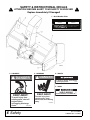
ST500 (Rev. 3/13/2009) 12030809 For F-Series Mow’n Machine Power Units OPERATOR'S MANUAL SNOWTHROWER TO THE DEALER: Assembly and proper installation of this product is the responsibility of the Woods® dealer. Read manual instructions and safety rules. Make sure all items on the Dealer’s Pre-Delivery and Delivery Check Lists in the Operator’s Manual are completed before releasing equipment to the owner. The dealer must complete the Product Registration online at the Woods Dealer Website or complete the mail-in form included with the Operator’s Manual. If using the mail-in form, the dealer is to return the prepaid postage portion to Woods, give one copy to the customer, and retain one copy. Failure to register the product does not diminish customer’s warranty rights. TO THE OWNER: Read this manual before operating your Woods equipment. The information presented will prepare you to do a better and safer job. Keep this manual handy for ready reference. Require all operators to read this manual carefully and become acquainted with all adjustment and operating procedures before attempting to operate. Replacement manuals can be obtained from your dealer. To locate your nearest dealer, check the Dealer Locator at www.WoodsEquipment.com, or in the United States and Canada call 1-800-319-6637. The equipment you have purchased has been carefully engineered and manufactured to provide dependable and satisfactory use. Like all mechanical products, it will require cleaning and upkeep. Lubricate the unit as specified. Observe all safety information in this manual and safety decals on the equipment. For service, your authorized Woods dealer has trained mechanics, genuine Woods service parts, and the necessary tools and equipment to handle all your needs. Use only genuine Woods service parts. Substitute parts will void the warranty and may not meet standards required for safe and satisfactory operation. Record the model number and serial number of your equipment in the spaces provided: Model: _______________________________ Date of Purchase: _____________________ Serial Number: (see Safety Decal section for location) ____________________________________ Provide this information to your dealer to obtain correct repair parts. Throughout this manual, the term NOTICE is used to indicate that failure to observe can cause damage to equipment. The terms CAUTION, WARNING, and DANGER are used in conjunction with the Safety-Alert Symbol (a triangle with an exclamation mark) to indicate the degree of hazard for items of personal safety. 2 Introduction Gen’l (Rev. 2/19/2008) TABLE OF CONTENTS INTRODUCTION . . . . . . . . . . . . . . . . . . . . . . . . . . . . . . . . . . . . . . . . . . . . . . 2 GENERAL INFORMATION . . . . . . . . . . . . . . . . . . . . . . . . . . . . . . . . . . . . . . 3 SAFETY RULES . . . . . . . . . . . . . . . . . . . . . . . . . . . . . . . . . . . . . . . . . . . . . . 4 SAFETY DECALS . . . . . . . . . . . . . . . . . . . . . . . . . . . . . . . . . . . . . . . . . . . . . 6 OPERATION . . . . . . . . . . . . . . . . . . . . . . . . . . . . . . . . . . . . . . . . . . . . . . . . . 7 OWNER SERVICE . . . . . . . . . . . . . . . . . . . . . . . . . . . . . . . . . . . . . . . . . . . . 8 ASSEMBLY . . . . . . . . . . . . . . . . . . . . . . . . . . . . . . . . . . . . . . . . . . . . . . . . . . 9 PARTS LISTS . . . . . . . . . . . . . . . . . . . . . . . . . . . . . . . . . . . . . . . . . . . . . . . 12 BOLT TORQUE CHARTS . . . . . . . . . . . . . . . . . . . . . . . . . . . . . . . . . . . . . . 14 BOLT SIZE CHART & ABBREVIATIONS . . . . . . . . . . . . . . . . . . . . . . . . . . 15 REPLACEMENT PARTS WARRANTY . . . . . . . . . . . . . . . . . . . . . . . . . . . . 16 PRODUCT WARRANTY . . . . . . . . . . . . . . . . . . . . . . . INSIDE BACK COVER GENERAL INFORMATION WARNING ■ Some illustrations in this manual show the snowthrower with safety shields removed to provide a better view. The snowthrower should never be operated with any safety shielding removed. The purpose of this manual is to assist you in operating and maintaining your snowthrower. Read it carefully. It furnishes information and instructions that will help you achieve years of dependable performance. These instructions have been compiled from extensive field 12030809 (Rev. 1/2/2007) experience and engineering data. Some information may be general in nature, due to unknown and varying operating conditions. However, through experience and these instructions, you should be able to develop procedures suitable to your particular situation. The illustrations and data used in this manual were current at the time of printing. However, due to possible inline production changes, your machine may vary slightly in detail. We reserve the right to redesign and change the machines as may be necessary without notification. Introduction 3 SAFETY RULES ATTENTION! BECOME ALERT! YOUR SAFETY IS INVOLVED! Safety is a primary concern in the design and manufacture of our products. Unfortunately, our efforts to provide safe equipment can be wiped out by an operator’s single careless act. Make sure the driveline spring-activated locking collar slides freely and is seated firmly in power unit PTO groove. Make sur e t he set screw s securely attach driveline to the attachment gearbox shaft. In addition to the design and configuration of equipment, hazard control and accident prevention are dependent upon the awareness, concern, judgement, and proper training of personnel involved in the operation, transport, maintenance and storage of equipment. The safety interlock system was installed for your protection. Do not disconnect, disable, override, or execute any action that would cause this system to malfunction. If malfunction occurs, stop all operation and contact dealer for repair. It has been said “The best safety device is an informed, careful operator.” We ask you to be that kind of operator. TRAINING Safety instructions are important! Read all attachment and power unit manuals; follow all safety rules and safety decal information. (Replacement manuals and safety decals are available from your dealer. To locate your nearest dealer, check the Dealer Locator at www.WoodsEquipment.com, or in the United States and Canada call 1-800-3196637.) Failure to follow instructions or safety rules can result in serious injury or death. If you do not understand any part of this manual and need assistance, see your dealer. Know your controls and how to stop engine and attachment quickly in an emergency. Operators must be instructed in and be capable of the safe operation of the equipment, its attachments, and all controls. Do not allow anyone to operate this equipment without proper instructions. Never allow children or untrained persons to operate equipment. PREPARATION Check that all hardware is properly installed. Always tighten to torque chart specifications unless instructed otherwise in this manual. Always wear relatively tight and belted clothing to avoid getting caught in moving parts. Wear sturdy, rough-soled work shoes and protective equipment for eyes, hair, hands, hearing, and head; and respirator or filter mask where appropriate. Make sure attachment is properly secured, adjusted, and in good operating condition. 4 Safety Make sure all safety decals are installed. Replace if damaged. (See Safety Decals section for location.) Make sure shields and guards are properly installed and in good condition. Replace if damaged. When using weight transfer system, correct counterweight must be used to maintain stability. See counterweight chart in power unit manual or contact dealer. When equipped with ROPS, total vehicle weight with all equipment, ballast, and operator must not exceed 2,590 lbs. Inspect and clear area of stones, branches, or other hard objects that might be thrown, causing injury or damage. OPERATION Never place any part of the body underneath implement/attachment or between its moving parts even when the engine has been turned off. Service work does not require going underneath unit. Mechanical failures, electrical failures, or operating controls can cause equipment to drop. Never place hands or body into discharge chute or auger to unclog. Stored energy can cause auger to quickly rotate when unclogging occurs and cause severe injury or amputation. Stop engine, remove key, disconnect driveline, and carefully unclog, using a sturdy piece of wood. Keep bystanders away from equipment. Never direct discharge toward people, animals, or property. Do not operate or transport equipment while under the influence of alcohol or drugs. Operate only in daylight or good artificial light. Keep hands, feet, hair, and clothing away from equipment while engine is running. Stay clear of all moving parts. ST500 Snowblower SR (Rev. 1/2/2007) SAFETY RULES ATTENTION! BECOME ALERT! YOUR SAFETY IS INVOLVED! When improperly operated, power unit can roll over or upset. Use of rollover protective structure (ROPS) with seat belt securely fastened will reduce the possibility of injury or death if rollover or upset occurs. Never allow riders on power unit or attachment. Do not operate PTO during transport. Do not operate auxiliary hydraulics during transport. Look down and to the rear and make sure area is clear before operating in reverse. Do not operate or transport on steep slopes. Use extreme care and reduce ground speed on slopes and rough terrain. equipment for eyes, hair, hands, hearing, and head; and respirator or filter mask where appropriate. Make sure attachment is properly secured, adjusted, and in good operating condition. Never place any part of the body underneath implement/attachment or between its moving parts even when the engine has been turned off. Service work does not require going underneath unit. Mechanical failures, electrical failures, or operating controls can cause equipment to drop. Do not put Mow’n Machine into service unless clutch is working properly. When the engine is at full throttle, PTO-driven accessories must stop within five seconds after the PTO switch is turned to “OFF.” See your dealer for replacement clutches. Watch for hidden hazards on the terrain during operation. Keep all persons away from operator control area while performing adjustments, service, or maintenance. Stop power unit and equipment immediately upon striking an obstruction. Turn off engine, remove key, inspect, and repair any damage before resuming operation. Tighten all bolts, nuts, and screws to torque chart specifications. Check that all cotter pins are installed securely to ensure equipment is in a safe condition before putting unit into service. Do not operate power unit with attachment removed. Attachment is required for power unit stability. Make sure all safety decals are installed. Replace if damaged. (See Safety Decals section for location.) MAINTENANCE Make sure shields and guards are properly installed and in good condition. Replace if damaged. Do not modify or alter or permit anyone else to modify or alter the equipment or any of its components in any way. STORAGE Always wear relatively tight and belted clothing to avoid getting caught in moving parts. Wear sturdy, rough-soled work shoes and protective Keep children and bystanders away from storage area. Block equipment securely for storage. ST500 Snowblower SR (Rev. 1/2/2007) Safety 5 SAFETY & INSTRUCTIONAL DECALS ATTENTION! BECOME ALERT! YOUR SAFETY IS INVOLVED! Replace Immediately If Damaged! 1 - Serial Number Plate MODEL NO. SERIAL NO. Woods Equipment Company Oregon, Illinois, U.S.A. 2 - 12030487A DANGER 3 - 12030480A DANGER 4 - 1004114 DANG NGER ER If shaft connection is visible, shield is missing. Replace shield before operating equipment. 1004114 5 - 18869 KEEP AWAY! To avoid injury from rotating parts, shut off engine before unclogging discharge chute. 12030487-A 6 Safety KEEP AWAY! DO NOT OPERATE - PUT SHIELD ON 18869-B DANGER SHIELD MISSING To avoid injury from rotating auger, keep hands, feet, and clothing away. 12030480-A (Rev. 3/13/2009) 12030809 (Rev. 1/2/2007) OPERATION WARNING Keep hands, feet, hair, and clothing away from equipment while engine is running. Stay clear of all moving parts. Make sure shields and guards are properly installed and in good condition. Replace if damaged. Never place hands or body into discharge chute or auger to unclog. Stored energy can cause auger to quickly rotate when unclogging occurs and cause severe injury or amputation. Stop engine, remove key, disconnect driveline, and carefully unclog, using a sturdy piece of wood. Keep all persons away from operator control area while performing adjustments, service, or maintenance. CAUTION Stop power unit and implement immediately upon striking an obstruction. Dismount power unit, using proper procedure. Inspect and repair any damage before resuming operation. IMPORTANT ■ When installing tire chains, be sure wheel spacer kit has been installed on both wheels. Chains will rub fenders if spacers are not installed. See your Mow'n Machine dealer for correct tire chains and spacer kits. PRE-OPERATION CHECK LIST (OWNER'S RESPONSIBILITY) ___ Check that all hardware and cotter pins are properly installed and secured. ___ Inspect area and remove stones, branches or other hard objects that might be thrown, causing injury or damage. ___ Do not allow riders. ___ Perform a functional check of the safety interlock system each time you operate the unit. Place both steering levers outward, start engine, engage PTO and then raise up out of the seat. The engine should die when you raise up. If it does not, do not operate unit until the safety interlock system has been repaired and operates properly. ___ Review and follow all safety rules and safety decal instructions on page 4 through page 6. ___ Check that all safety decals are installed and in good condition. Replace if damaged. ___ Check that all shields and guards are properly installed and in good condition. Replace if damaged. ___ Check that all hardware and cotter pins are properly installed and secured. Be sure all fasteners on snowthrower and mounts are secure and all shields are in place before operating unit. For clearing paved surfaces, adjust skids to allow bottom of auger housing to scrape the surface being cleared. For cleaning unpaved surfaces, adjust skids to raise bottom of auger housing 3/4" above surface to help avoid picking up rocks or other loose material. Be sure bottom surfaces of skids are parallel with surface being cleaned. Adjust discharge spout and deflector to direct snow away form operator as much as possible. Do not direct discharge toward windows, bystanders or objects. Operate engine at 3/4 to full throttle. Tire chains are available for added traction. 12030809 (Rev. 1/2/2007) Operation 7 OWNER SERVICE The information in this section is written for operators who possess basic mechanical skills. If you need help, your dealer has trained service technicians available. For you protection, read and follow all safety information in this manual. Routine maintenance is not necessary for bearings or gearbox as they are permanently lubricated. NOTE: If gearbox oil is removed, refill with 6 ounces of 80W-90 weight oil. Auger drive chain, located under chain shield on right side of auger housing, should be checked for proper tension and lubricated at least each operating season or more frequently if used heavy. Lubricate chain with motor oil. Be sure to install chain shield after servicing. Snowthrower skids are reversible. Move left skid to right side and right skid to left side, being sure to keep rounded end toward the front. WARNING WARNING Never place any part of the body underneath implement/attachment or between its moving parts even when the engine has been turned off. Service work does not require going underneath unit. Mechanical failures, electrical failures, or operating controls can cause equipment to drop. CAUTION Always wear relatively tight and belted clothing to avoid getting caught in moving parts. Wear sturdy, rough-soled work shoes and protective equipment for eyes, hair, hands, hearing, and head; and respirator or filter mask where appropriate. IMPORTANT Before performing any service or maintenance, lower attachment to ground, turn off power unit engine, remove key, and disconnect battery ground cable (negative -). ■ Do not use high-pressure water or steam to clean the engine or drive compartment. Water and cleaning detergent may damage electrical components and terminals, possibly leading to component and safety circuit failure. NOTES 8 Owner Service 12030809 (Rev. 1/2/2007) ASSEMBLY Snowthrower Set-up Instructions Attaching Snowthrower to Tractor Remove step and replace with the short step included with snowthrower. Remove cotter pin on end of step rod and slide out. Install shorter step and replace rod and cotter pin. Slide lever mount (27) and lift mount (28) onto lift (29). Slide this assembly into tubes below footrest as shown in Figure 1. Secure with cap screws (73) and nuts (75) provided. Attach snowthrower mount (26) to lower back side of auger housing with cap screws (59) and flange locknuts (69). Refer to page 12. Attach upper spout screws (50), spacers (48), washers (49), (51) and hex nuts (52). Spout should be approximately 180 degrees when spout pushed down to release spout lock. (2) with cap lock washers free to rotate handle (5) is WARNING Make sure the driveline spring-activated locking collar slides freely and is seated firmly in power unit PTO groove. Make sur e t he set screw s securely attach driveline to the attachment gearbox shaft. The tractor must comply with counterweight requirements before attaching snowthrower. See Counterweight Requirement Chart in the tractor manual or contact your dealer. Place tractor and snowthrower on a level surface. Shut off tractor engine and remove key. Open tractor hydrostat dump valve and maneuver tractor behind snowthrower as close as possible. Connect driveline, Figure 1, to tractor PTO. Attach snowthrower mount (26) to bottom holes of tractor mount as shown. Secure with attaching pins (63). Install lift chains to lift chain mechanism and snowthrower mount. Adjust eyebolt for even lift. Tractor Frame 28 73 PTO 29 75 26. 27. 28. 29. 59. 63. 69. 73. 75. Snowthrower mount Mount lift (right) Mount lift (left) Lift hand lever 3/8 NC x 1-3/4 Hex head cap screw Attaching pin 3/8 NC Serrated flange nut 1/4 NC x 1-1/2 Hex head cap screw 1/4 NC Hex lock nut 26 27 63 59 69 CD00218011 Figure 1. Snowthrower Attachment to Tractor 12030809 (Rev. 1/2/2007) Assembly 9 Storage Periodically or Before Extended Storage WARNING ● Clean large debris such as clumps of dirt, grass, crop residue, etc. from machine. ● Remove the remainder using a low-pressure water spray. Do not operate power unit with attachment removed. Attachment is required for power unit stability. 1. Be careful when spraying near scratched or torn safety decals or near edges of decals as water spray can peel decal off surface. Wood blocks can be used to support the rear of the snowthrower deck when not attached to the tractor. Raise snowthrower deck to it's highest height to provide the necessary clearance for installing blocks. Lower rear of snowthrower on blocks to take the weight off of the snowthrower lift components. ● Disconnect PTO driveline, lift mounts (27 & 28) and spring-loaded mount pins (63). See Figure 1. Inspect machine and replace worn or damaged parts. ● Sand down scratches and the edges of areas of missing paint and coat with Woods spray paint of matching color (purchase from your Woods dealer). ● Replace any safety decals that are missing or not readable (supplied free by your Woods dealer). See Safety Decals section for location drawing. Open tractor hydrostat dump valves so that tractor can be maneuvered away from snowthrower. Refer to Figure 2. 2. Be careful when spraying near chipped or scratched paint as water spray can lift paint. 3. If a pressure washer is used, follow the advice of the pressure washer manufacturer. PRE-DELIVERY CHECK LIST 2 Inspect the equipment thoroughly after assembly to ensure it is set up properly before delivering it to the customer. ___ Check that all safety decals are installed and in good condition. Replace if damaged. ___ Check that shields and guards are properly installed and in good condition. Replace if damaged. ___ Check that all cotter pins and safety pins are properly installed. Replace if damaged ___ Check and grease all lubrication points. 1. 2. Dump valve lever Dump valve lever lock-up 1 DELIVERY CHECK LIST (DEALER’S RESPONSIBILITY) ___ Show customer how to make adjustments. Figure 2. Dump Valve CLEANING After Each Use ● Remove large debris such as clumps of dirt, grass, crop residue, etc. from machine. ● Inspect machine and replace worn or damaged parts. ● Replace any safety decals that are missing or not readable. 10 Assembly ___ Show customer how to make sure driveline is properly installed and that spring-activated locking pin or collar slides freely and is seated in groove on tractor PTO shaft. ___ Explain to customer the potential crushing hazards of going underneath raised equipment. Instruct customer that service work does not require going underneath unit and never to do so. ___ Make customer aware of optional equipment available so that customer can make proper choices as required. 12030809 (Rev. 1/2/2007) ___ Present Operator's Manual and request that customer and all operators read it before operating equipment. Point out the manual safety rules, explain their meanings and emphasize the increased safety hazards that exist when safety rules are not followed. ___ Point out the safety decals. Explain their meaning and the need to keep them in place and in good condition. Emphasize the increased safety hazards when instructions are not followed. ___ Point out all guards and shields. Explain their importance and the safety hazards that exist when not kept in place and in good condition. ___ Instruct customer how to lubricate and explain importance of lubrication. NOTES 12030809 (Rev. 1/2/2007) Assembly 11 12 Parts 28 73 36 30 55 82 56 29 77 62 27 38 39 25 57 63 37 35 33 59 74 24 70 61 36 80 - DECAL SET 81 - MODEL DECAL 26 57 68 8 35 47 69 60 30 34 32 59 5 44 70 72 21 19 4 78 69 41 22 46 67 6 7 20 75 55 54 58 18 74 64 76 23 73 2 50 4 11 10 60 44 49 48 51 78 53 3 8 35 42 66 15 43 67 16 12 53 53 35 34 52 1 71 9 65 13 14 17 31 40 83 53 33 53 ST500 SNOWTHROWER MAIN ASSEMBLY 12030809 (Rev. 1/2/2007) ST500 SNOWTHROWER MAIN ASSEMBLY REF PART QTY DESCRIPTION REF PART QTY DESCRIPTION 1 72320 1 Auger housing 41 902 1 5/8 - 11 x 2 Hex head cap screw 2 12020152 1 Upper spout 42 692 4 5/8 Standard flat washer 3 12020145 1 Spout deflector 43 6239 1 5/8 NC Hex locknut 4 70454 2 Thumbscrew, 5/16 - female 44 70073 2 3/16 Square x 1 key 5 70455 1 Spout handle 46 62233 1 3/16 x 3/4 Woodruff key (output side) 6 12020240 1 Spout lock rod 47 64051 1 5/32 x 5/8 Woodruff key (input side) 7 70388 1 Compression spring, 3/4 x .08 x 2 48 12030807 1 Spout pivot spacer 8 72102 2 Skid 49 12030806 1 Spout retainer ring 9 70458 1 Auger, 1” shaft 50 10378 3 1/4 x 1 Hex head cap screw 10 70459 1 Snow deflector 51 62521 3 1/4 NC Flange whiz nut 16148 16 5/16 NC x 3/4 Carriage bolt 11 70460 1 3/4 Ball bearing with locking collar 53 12 70461 2 Bolt flange 54 3598 1 1/2 SAE Washer 13 72321 1 Chain shield 55 3597 3 1/8 x 1 Cotter pin 14 70463 1 Sprocket, 40B 30 x 1 56 565 2 3/8 Standard flat washer 15 70464 1 Idler, 40 - 18 x 5/8 57 835 6 3/8 - 16 Hex nut, plated 16 70465 1 Sprocket, 40B 11 x 3/4 58 70159 1 Handle grip .5 17 72322 1 #40 Chain 59 920 4 3/8 - 16 x 1-3/4 Hex head cap screw 18 70203 1 Power shaft 60 838 2 3/8 Lockwasher 19 70467 1 3/4 Coupling sprocket 50-12 61 4115 2 3/16 x 1-1/8 Roll pin 20 70468 1 7/8 Coupling sprocket 62 66510 2 Spring 21 70469 1 #50 Chain coupler 63 72403 2 Pin 22 70247 1 Gearbox, T 7/8 shaft 64 12169 2 3/8 NC x 1-1/4 Hex head cap screw GR5 23 70470 1 Shaft shield 24 70471 1 Shaft coupling shield 65 90016237 2 5/16 x 5/16 Socket head set screw 25 74025 1 Drive half-F 6R, 11.5 -or- 66 90011053 1 Machine bushing 25 65689 1 Cross & Bearing, Series 6N 67 67063 6 1/4 x 1/4 Socket set screw 62153 2 3/8 NC x 1 Whiz lock bolt 26 12020247 1 Snowthrower mount 68 27 12020272 1 Lever mount 69 14350 4 3/8 NC Serrated flanged hex locknut 28 12020273 1 Lift mount (left hand) 70 5337 4 1/4 NC x 1/2 Hex head cap screw 29 1 Snowthrower lift 71 62521 6 1/4 NC Serrated flanged hex locknut 3184 1 1/4 NC x 1-1/4 Hex head cap screw 70727 30 71170 2 Lift chain 72 31 70474 1 Right side extension 73 62788 3 1/4 NC x 1-1/2 Hex head cap screw 32 70475 1 Left side extension 74 6096 2 5/16 NC x 3/4 Hex head cap screw 33 70476 2 Extension brace 75 6128 2 1/4 NC Self lock hex nut 839 2 3/8 NC x 1 Hex head cap screw 34 70176 2 1” Ball bearing with locking collar 76 35 70477 4 Bolt flange 77 90016251 2 3/8 x 3/8 Socket set screw 36 71171 2 3/8 - 16 x 2 Eyebolt 78 2 5/16 Star washer 37 12030442 1 Lever guide 80 12010072 1 Decal package 1 ST500 Model decal 90011132 38 70766 1 Push rod grip 81 12030808 39 7530700 1 Handle grip, thumb release 82 73926 1 Assy. foot rest, short 40 71172 1 Blade 83 6593 1 Key, 1/4 x 1/4 x 1 12030809 (Rev. 1/2/2007) Parts 13 BOLT TORQUE CHART Always tighten hardware to these values unless a different torque value or tightening procedure is listed for a specific application. Fasteners must always be replaced with the same grade as specified in the manual parts list. Always use the proper tool for tightening hardware: SAE for SAE hardware and Metric for metric hardware. Make sure fastener threads are clean and you start thread engagement properly. All torque values are given to specifications used on hardware defined by SAE J1701 MAR 99 & J1701M JUL 96. SAE Bolt Head Identification SAE SERIES TORQUE CHART A SAE Grade 2 (No Dashes) SAE Grade 8 (6 Radial Dashes) SAE Grade 5 (3 Radial Dashes) MARKING ON HEAD A SAE 2 SAE 5 SAE 8 Diameter (Inches) Wrench Size lbs-ft N-m lbs-ft N-m lbs-ft N-m 1/4" 5/16" 7/16" 1/2" 6 12 8 17 10 19 13 26 14 27 18 37 3/8" 7/16" 9/16" 5/8" 23 36 31 48 35 55 47 75 49 78 67 106 1/2" 9/16" 3/4" 13/16" 55 78 75 106 85 121 115 164 120 171 163 232 5/8" 3/4" 15/16" 1-1/8" 110 192 149 261 170 297 230 403 240 420 325 569 7/8" 1" 1-5/16" 1-1/2" 306 467 416 634 474 722 642 979 669 1020 907 1383 A METRIC SERIES TORQUE CHART A Metric Bolt Head Identification 8.8 Metric Grade 8.8 10.9 Metric Grade 10.9 COARSE THREAD FINE THREAD MARKING ON HEAD MARKING ON HEAD A Diameter & Thread Pitch (Millimeters) Wrench Size N-m lbs-ft N-m lbs-ft N-m lbs-ft N-m lbs-ft Diameter & Thread Pitch (Millimeters) 6 x 1.0 10 mm 8 6 11 8 8 6 11 8 6 x 1.0 8 x 1.25 10 x 1.5 13 mm 16 mm 20 39 15 29 27 54 20 40 21 41 16 30 29 57 22 42 8 x 1.0 10 x 1.25 12 x 1.75 14 x 2.0 18 mm 21 mm 68 109 50 80 94 151 70 111 75 118 55 87 103 163 76 120 12 x 1.25 14 x 1.5 16 x 2.0 18 x 2.5 24 mm 27 mm 169 234 125 172 234 323 173 239 181 263 133 194 250 363 184 268 16 x 1.5 18 x 1.5 20 x 2.5 22 x 2.5 30 mm 34 mm 330 451 244 332 457 623 337 460 367 495 270 365 507 684 374 505 20 x 1.5 22 x 1.5 24 x 3.0 30 x 3.0 36 mm 46 mm 571 1175 421 867 790 1626 583 1199 623 1258 459 928 861 1740 635 1283 24 x 2.0 30 x 2.0 Typical Washer Installations Bolt Metric 8.8 Lock Washer Metric 10.9 Metric 8.8 Metric 10.9 Flat Washer 8/9/00 14 Appendix Bolt Torque & Size Charts (Rev. 3/28/2007) BOLT SIZE CHART NOTE: Chart shows bolt thread sizes and corresponding head (wrench) sizes for standard SAE and metric bolts. SAE Bolt Thread Sizes 5/16 3/8 1/2 IN MM 5/8 3/4 7/8 1 2 3 4 5 6 7 25 50 75 100 125 150 175 Metric Bolt Thread Sizes 8MM 10MM 12MM 14MM 16MM 18MM ABBREVIATIONS AG .............................................................. Agriculture ASABE.................... American Society of Agricultural & Biological Engineers (formerly ASAE) ASAE ....... American Society of Agricultural Engineers ATF ............................... Automatic Transmission Fluid BSPP .............................British Standard Pipe Parallel BSPTM ................ British Standard Pipe Tapered Male CV.....................................................Constant Velocity CCW .............................................. Counter-Clockwise CW............................................................... Clockwise F ...................................................................... Female FT .............................................................. Full Thread GA .................................................................... Gauge GR (5, etc.) ........................................... Grade (5, etc.) HHCS ........................................Hex Head Cap Screw HT ........................................................... Heat-Treated JIC .................Joint Industry Council 37° Degree Flare LH .................................................................Left Hand LT........................................................................... Left m......................................................................... Meter mm................................................................ Millimeter M.......................................................................... Male Bolt Torque & Size Charts (Rev. 3/28/2007) MPa......................................................... Mega Pascal N.......................................................................Newton NC ...................................................... National Coarse NF ...........................................................National Fine NPSM..................... National Pipe Straight Mechanical NPT .......................................... National Pipe Tapered NPT SWF ......... National Pipe Tapered Swivel Female ORBM .......................................... O-Ring Boss - Male P...........................................................................Pitch PBY ...................................................... Power-Beyond psi.......................................... Pounds per Square Inch PTO ..................................................... Power Take Off QD ....................................................Quick Disconnect RH ..............................................................Right Hand ROPS ........................... Roll-Over Protective Structure RPM ........................................Revolutions Per Minute RT ....................................................................... Right SAE ..........................Society of Automotive Engineers UNC ..................................................... Unified Coarse UNF...........................................................Unified Fine UNS...................................................... Unified Special Appendix 15 LIMITED WARRANTY (Mow’n Machine Zero-Turn Mowers and Woods Boundary Utility Vehicles) TM TM Please Enter Information Below and Save For Future Reference. Date Purchased: __________________________ From (Dealer):______________________________________ Model Number: __________________________ Serial Number: _____________________________________ WHAT IS COVERED: Woods Equipment Company (“WOODS”) warrants Mow’n MachineTM zero-turn mowers and attachments and Woods BoundaryTM utility vehicles, accessories and attachments to be free from defect in material and workmanship for the warranty periods listed below. FOR HOW LONG: Mow’n Machine Model #CZ1736K, CZ1948K, CZ1952K, CZ2361, ME1952K, ME2661B, MZ2552K, MZ2561K, MZ2761, MZ3761K, MZ3772K, MZ2661KL & attachments are warranted for two (2) years from the date of delivery to the original purchaser or 2000 hours of operation, whichever occurs first. Purchaser may opt for a warranty of five (5) years from the date of delivery to the original purchaser or 500 hours of operation, whichever occurs first. The dealer must specify the special warranty term on the original, dated bill of sale and a copy must be provided with all warranty claims. Mow’n Machine model numbers CZR2242B and CZR2652B are warranted for residential use for three (3) years from the date of delivery to the original purchaser or for commercial use for 90 days from the date of delivery to the original purchaser. Mow’n Machine Model #FE21B, FZ21D, FZ23B, FZ25D, FZ28K & attachments are warranted for two (2) years from the date of delivery to the original purchaser or 2000 hours of operation, whichever occurs first. In addition, Mow’n Machine ME and MZ Series Models, serial number XXXXXXXX300 and above, have a Limited Lifetime Warranty on deck, deck cradle, and engine deck for the life of the machine to the original retail purchaser. Woods Boundary utility vehicle Model #MAV350, MAV480, MAV4x4, accessories & attachments are warranted for two (2) years from the date of delivery to the original purchaser. IMPLIED WARRANTIES OF MERCHANTABILITY AND/OR FITNESS FOR A PARTICULAR PURPOSE ARE LIMITED IN DURATION TO THE DURATION OF THE WRITTEN WARRANTY PERIODS LISTED ABOVE. Some states do not allow limitations on how long an implied warranty lasts, so the above limitation may not apply to you. WHO IS COVERED: This Warranty is extended solely to the original purchaser of the product. Should the original purchaser sell or otherwise transfer the product to a third party, this Warranty does not transfer to the third party purchaser in any way. There are no third party beneficiaries of this Warranty. WHAT IS NOT COVERED: This Warranty does not cover normal wear or tear, or normal maintenance items, or any damage, failure or loss caused by: 1. Improper operation, improper maintenance, misuse, or an accident; 2. Any modification or repair by someone other than WOODS, a WOODS’ authorized dealer or distributor, and/or a WOODS’ authorized service center; or 3. Repairs made with parts other than those obtained through WOODS. WOODS makes no warranty, express or implied, with respect to engines, batteries, tires or other parts or accessories with respect to which the manufacturer provides a separate warranty. WHAT WOODS WILL DO TO CORRECT PROBLEMS: WOODS’ obligation under this Warranty is limited to, at WOODS’ option, the repair or replacement, free of charge, of the product if the product is defective or in noncompliance with this Warranty. The product must be returned to WOODS with proof of purchase within thirty (30) days after such defect or noncompliance is discovered or should have been discovered, routed through the dealer and distributor from whom the purchase was made, transportation charges prepaid. WOODS shall complete such repair or replacement within a reasonable time after WOODS receives the product. OTHER LIMITATIONS: WOODS shall not be liable for any incidental or consequential losses, damages or expenses, arising directly or indirectly from the product, whether such claim is based upon breach of contract, breach of warranty, negligence, strict liability in tort or any other legal theory. Without limiting the foregoing, WOODS shall not be liable for any damages relating to (i) lost profits, business, revenues or goodwill; (ii) any expense or loss incurred for labor, supplies, substitute machinery or rental; or (iii) any other type of damage to property or economic loss. Some states do not allow the exclusion or limitation of incidental or consequential damages, so the above limitations may not apply to you. No agent, representative, dealer, distributor, service person, salesperson, or employee of any company, including without limitation, WOODS, its authorized dealers, distributors, and service centers, is authorized to alter, modify, or enlarge this Warranty. HOW STATE LAW APPLIES: This Warranty gives you specific legal rights, and you may also have other rights which vary from state to state. QUESTIONS: Answers to any questions regarding warranty service and locations may be obtained by contacting: Woods Equipment Company 2606 South Illinois Route 2 Post Office Box 1000 Oregon, Illinois 61061 800-319-6637 tel 800-399-6637 fax www.WoodsEquipment.com F-8045 MM & Boundary (Rev. 12/1/2008) LIMITED WARRANTY (Mow’n Machine Zero-Turn Mower and Woods Boundary Utility Vehicle Replacement Parts) TM TM Woods Equipment Company (“WOODS”) warrants replacement parts for Mow’n Machine zero-turn mowers and attachments and Woods Boundary utility vehicles, accessories and attachments to be free from defect in material and workmanship for a period of ninety (90) days from the date of delivery of the product to the original purchaser. TM TM IMPLIED WARRANTIES OF MERCHANTABILITY AND/OR FITNESS FOR A PARTICULAR PURPOSE ARE LIMITED IN DURATION TO A PERIOD OF NINETY (90) DAYS FROM THE DATE OF DELIVERY OF THE PRODUCT TO THE ORIGINAL PURCHASER. Some states do not allow limitations on how long an implied warranty lasts, so the above limitation may not apply to you. This Warranty is extended solely to the original purchaser of the product. Should the original purchaser sell or otherwise transfer the product to a third party, this Warranty does not transfer to the third party purchaser in any way. There are no third party beneficiaries of this Warranty. This Warranty does not cover normal wear or tear, or normal maintenance items, or any damage, failure or loss caused by improper operation, improper maintenance, misuse, or an accident. WOODS’ obligation under this Warranty is limited to, at WOODS’ option, the repair or replacement, free of charge, of the product if the product is defective or in noncompliance with this Warranty. The product must be returned to WOODS with proof of purchase within thirty (30) days after such defect or noncompliance is discovered or should have been discovered, routed through the dealer and distributor from whom the purchase was made, transportation charges prepaid. WOODS shall complete such repair or replacement within a reasonable time after WOODS receives the product. WOODS shall not be liable for any incidental or consequential losses, damages or expenses, arising directly or indirectly from the product, whether such claim is based upon breach of contract, breach of warranty, negligence, strict liability in tort or any other legal theory. Without limiting the foregoing, WOODS shall not be liable for any damages relating to (i) lost profits, business, revenues or goodwill; (ii) any expense or loss incurred for labor, supplies, substitute machinery or rental; or (iii) any other type of damage to property or economic loss. Some states do not allow the exclusion or limitation of incidental or consequential damages, so the above limitations may not apply to you. No agent, representative, dealer, distributor, service person, salesperson, or employee of any company, including without limitation, WOODS, its authorized dealers, distributors, and service centers, is authorized to alter, modify, or enlarge this Warranty. This Warranty gives you specific legal rights, and you may also have other rights which may vary from state to state. Answers to any questions regarding warranty service and locations may be obtained by contacting: F-8495 MM & Boundary Repair Parts (Rev. 2/15/2006) Woods Equipment Company 2606 South Illinois Route 2 Post Office Box 1000 Oregon, Illinois 61061 USA 800-319-6637 tel 800-399-6637 fax www.WoodsEquipment.com ©2001 Woods Equipment Company. All rights reserved. WOODS and the Woods logo are trademarks of Woods Equipment Company. All other trademarks, trade names, or service marks not owned by Woods Equipment Company that appear in this manual are the property of their respective companies or mark holders. Specifications subject to change without notice.