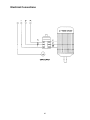
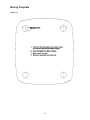
1
Operating Instructions and Parts Manual
Powered Stock Feeder for Table Saws
Model PF3-EZ
WMH TOOL GROUP, Inc.
2420 Vantage Drive
Elgin, Illinois 60123
Ph.: 800-274-6848
www.powermatic.com
Part No. M-1790814
Revision B 3/08
Copyright © 2008 WMH Tool Group
Warranty and Service
WMH Tool Group, Inc., warrants every product it sells. If one of our tools needs service or repair, one of our Authorized Service
Centers located throughout the United States can give you quick service. In most cases, any of these WMH Tool Group
Authorized Service Centers can authorize warranty repair, assist you in obtaining parts, or perform routine maintenance and
major repair on your POWERMATIC® tools. For the name of an Authorized Service Center in your area call 1-800-274-6848.
MORE INFORMATION
WMH Tool Group is consistently adding new products to the line. For complete, up-to-date product information, check with your
local WMH Tool Group distributor, or visit powermatic.com.
WARRANTY
POWERMATIC products carry a limited warranty which varies in duration based upon the product.
WHAT IS COVERED?
This warranty covers any defects in workmanship or materials subject to the exceptions stated below. Cutting tools, abrasives
and other consumables are excluded from warranty coverage.
WHO IS COVERED?
This warranty covers only the initial purchaser of the product.
WHAT IS THE PERIOD OF COVERAGE?
The general POWERMATIC warranty lasts for the time period specified in the product literature of each product.
WHAT IS NOT COVERED?
The Five Year Warranty does not cover products used for commercial, industrial or educational purposes. Products with a Five
Year Warranty that are used for commercial, industrial or education purposes revert to a One Year Warranty. This warranty does
not cover defects due directly or indirectly to misuse, abuse, negligence or accidents, normal wear-and-tear, improper repair or
alterations, or lack of maintenance.
HOW TO GET SERVICE
The product or part must be returned for examination, postage prepaid, to a location designated by us. For the name of the
location nearest you, please call 1-800-274-6848.
You must provide proof of initial purchase date and an explanation of the complaint must accompany the merchandise. If our
inspection discloses a defect, we will repair or replace the product, or refund the purchase price, at our option.
We will return the repaired product or replacement at our expense unless it is determined by us that there is no defect, or that the
defect resulted from causes not within the scope of our warranty in which case we will, at your direction, dispose of or return the
product. In the event you choose to have the product returned, you will be responsible for the handling and shipping costs of the
return.
HOW STATE LAW APPLIES
This warranty gives you specific legal rights; you may also have other rights which vary from state to state.
LIMITATIONS ON THIS WARRANTY
WMH TOOL GROUP LIMITS ALL IMPLIED WARRANTIES TO THE PERIOD OF THE LIMITED WARRANTY FOR EACH
PRODUCT. EXCEPT AS STATED HEREIN, ANY IMPLIED WARRANTIES OR MERCHANTABILITY AND FITNESS ARE
EXCLUDED. SOME STATES DO NOT ALLOW LIMITATIONS ON HOW LONG THE IMPLIED WARRANTY LASTS, SO THE
ABOVE LIMITATION MAY NOT APPLY TO YOU.
WMH TOOL GROUP SHALL IN NO EVENT BE LIABLE FOR DEATH, INJURIES TO PERSONS OR PROPERTY, OR FOR
INCIDENTAL, CONTINGENT, SPECIAL, OR CONSEQUENTIAL DAMAGES ARISING FROM THE USE OF OUR PRODUCTS.
SOME STATES DO NOT ALLOW THE EXCLUSION OR LIMITATION OF INCIDENTAL OR CONSEQUENTIAL DAMAGES, SO
THE ABOVE LIMITATION OR EXCLUSION MAY NOT APPLY TO YOU.
WMH Tool Group sells through distributors only. The specifications in WMH catalogs are given as general
information and are not binding. Members of WMH Tool Group reserve the right to effect at any time,
without prior notice, those alterations to parts, fittings, and accessory equipment which they may deem
necessary for any reason whatsoever.
2
Table of Contents
Warranty and Service .............................................................................................................................. 2
Table of Contents .................................................................................................................................... 3
Warning................................................................................................................................................... 4
Introduction ............................................................................................................................................. 6
Description .............................................................................................................................................. 6
Specifications .......................................................................................................................................... 6
Features.................................................................................................................................................. 7
Unpacking ............................................................................................................................................... 8
Contents of Shipping Containers .......................................................................................................... 8
Assembly ................................................................................................................................................ 9
Grounding Instructions........................................................................................................................... 11
Extension Cords................................................................................................................................. 12
Adjustments .......................................................................................................................................... 12
Swing................................................................................................................................................. 12
Raise/Lower....................................................................................................................................... 12
Forward/Back..................................................................................................................................... 12
Rotate................................................................................................................................................ 12
Pivot .................................................................................................................................................. 13
Operating Controls ................................................................................................................................ 13
Switch................................................................................................................................................ 13
Speed Selection................................................................................................................................. 13
Operation .............................................................................................................................................. 13
General Operating Instructions........................................................................................................... 14
Spacers ............................................................................................................................................. 14
Rollers ............................................................................................................................................... 15
Drive Belt Replacement...................................................................................................................... 15
Lubrication ......................................................................................................................................... 15
Troubleshooting..................................................................................................................................... 17
Replacement Parts ................................................................................................................................ 18
Parts List: Stand Assembly................................................................................................................. 19
Stand Assembly................................................................................................................................. 21
Parts List: PF3-EZ Feeder.................................................................................................................. 22
PF3-EZ Feeder .................................................................................................................................. 24
Electrical Connections ........................................................................................................................... 25
Boring Template .................................................................................................................................... 27
3
Warning
1. Read and understand the entire owners manual before attempting assembly or operation.
2. Read and understand the warnings posted on the machine and in this manual. Failure to comply with
all of these warnings may cause serious injury.
3. Replace the warning labels if they become obscured or removed.
4. This stock feeder is designed and intended for use by properly trained and experienced personnel
only. If you are not familiar with the proper and safe operation of a stock feeder, do not use until
proper training and knowledge have been obtained.
5. Do not use this stock feeder for other than its intended use. If used for other purposes, WMH Tool
Group disclaims any real or implied warranty and holds itself harmless from any injury that may result
from that use.
6. Always wear approved safety glasses/face shield while using this stock feeder. Everyday eyeglasses
only have impact resistant lenses; they are not safety glasses.
7. Before operating this stock feeder, remove tie, rings, watches and other jewelry, and roll sleeves up
past the elbows. Remove all loose clothing and confine long hair. Non-slip footwear or anti-skid floor
strips are recommended. Do not wear gloves.
8. Wear ear protectors (plugs or muffs) during extended periods of operation.
9. Some dust created by power sanding, sawing, grinding, drilling and other construction activities
contain chemicals known to cause cancer, birth defects or other reproductive harm. Some examples
of these chemicals are:
•
Lead from lead based paint.
•
•
Crystalline silica from bricks, cement and other masonry products.
Arsenic and chromium from chemically treated lumber.
Your risk of exposure varies, depending on how often you do this type of work. To reduce your
exposure to these chemicals, work in a well-ventilated area and work with approved safety
equipment, such as face or dust masks that are specifically designed to filter out microscopic
particles.
10. Do not operate this machine while tired or under the influence of drugs, alcohol or any medication.
11. Make certain the switch is in the OFF position before connecting the machine to the power supply.
12. Make certain the machine is properly grounded.
13. Make all machine adjustments or maintenance with the machine unplugged from the power source.
14. Remove adjusting keys and wrenches. Form a habit of checking to see that keys and adjusting
wrenches are removed from the machine before turning it on.
15. Keep safety guards in place at all times when the machine is in use. If removed for maintenance
purposes, use extreme caution and replace the guards immediately.
16. Make sure the stock feeder is firmly secured to the table saw before use.
17. Check damaged parts. Before further use of the machine, a guard or other part that is damaged
should be carefully checked to determine that it will operate properly and perform its intended
function. Check for alignment of moving parts, binding of moving parts, breakage of parts, mounting
and any other conditions that may affect its operation. A guard or other part that is damaged should
be properly repaired or replaced.
18. Provide for adequate space surrounding work area and non-glare, overhead lighting.
19. Keep the floor around the machine clean and free of scrap material, oil and grease.
20. Keep visitors a safe distance from the work area. Keep children away.
4
blahblahblah
21. Make your workshop child proof with padlocks, master switches or by removing starter keys.
22. Give your work undivided attention. Looking around, carrying on a conversation and “horse-play” are
careless acts that can result in serious injury.
23. Maintain a balanced stance at all times so that you do not fall or lean against moving parts. Do not
overreach or use excessive force to perform any machine operation.
24. Use the right tool at the correct speed and feed rate. Do not force a tool or attachment to do a job for
which it was not designed. The right tool will do the job better and safer.
25. Use recommended accessories; improper accessories may be hazardous.
26. Maintain tools with care. Keep tools sharp and clean for the best and safest performance. Follow
instructions for lubricating and changing accessories.
27. Turn off the stock feeder and the table saw before cleaning. Use a brush or compressed air to
remove chips or debris — do not use your hands.
28. Do not stand on the machine. Serious injury could occur if the machine tips over.
29. Never leave the machine running unattended. Turn the power off and do not leave the machine until it
comes to a complete stop.
30. Remove loose items and unnecessary work pieces from the area before starting the machine.
Familiarize yourself with the following safety notices used in this manual:
This means that if precautions are not heeded, it may result in minor injury and/or
possible machine damage.
This means that if precautions are not heeded, it may result in serious injury or possibly
even death.
- - SAVE THESE INSTRUCTIONS - -
5
Introduction
This manual is provided by WMH Tool Group, Inc. covering the safe operation and maintenance
procedures for a Model PF3-EZ Stock Feeder. This manual contains instructions on installation, safety
precautions, general operating procedures, maintenance instructions and parts breakdown. This machine
has been designed and constructed to provide years of trouble free operation if used in accordance with
instructions set forth in this manual. If there are any questions or comments, please contact either your
local supplier or WMH Tool Group. WMH Tool Group can also be reached at our web site:
www.wmhtoolgroup.com.
Description
The PF3-EZ Stock Feeder can be mounted to a table saw to safely and effectively feed workpieces into
the blade. The Stock Feeder has a continuous duty motor and lubricated gearbox that transmit power
through roller chain and sprockets to the feed rollers, providing superior positive feeding for all types of
materials. Heavy-duty locking mechanisms secure the feeder in position. The roller system is
“maintenance-friendly” allowing you to replace a single roller if necessary, instead of a complete set.
Specifications
Model number ............................................................................................................................... PF3-EZ
Stock number (230V)................................................................................................................. 1790814K
Stock number (460V)................................................................................................................. 1790815K
Motor............................................................................................................................ TEFC, 3/4HP, 3Ph
Height with handle (in.) ....................................................................................................................... 31.5
Width (in.)......................................................................................................................................... 21.85
Length with handle and arm fully extended (in.) .................................................................................. 51.5
Elevating Column diameter (in.)............................................................................................................... 2
Horizontal Arm diameter (in.) ................................................................................................................ 2.3
Rollers (dia. x w) (in.)..............................................................................................4-3/4 x 1, polyurethane
Rotation............................................................................................................................. forward/reverse
Number of speeds .........................................................................................................................variable
Range of speeds (FPM)............................................................................................................... 6.5 to 66
Distance between rollers, center-to-center (in.) ........................................................................5.93 to 5.31
Swing (deg.) ........................................................................................................................................ 360
Vertical movement (in.)....................................................................................................................... 8.33
Horizontal movement (in.)................................................................................................................. 29.33
Maximum height of rollers parallel to table top (in.).............................................................................. 7.47
Approximate shipping weight (lbs.) ...................................................................................................... 180
Approximate net weight (lbs.)............................................................................................................... 170
The above specifications were current at the time this manual was published, but because of our policy of
continuous improvement, WMH Tool Group reserves the right to change specifications at any time and
without prior notice, without incurring obligations.
6
Features
7
1
3
1
1
1
Unpacking
Open shipping containers and check for
shipping damage. Report any damage
immediately to your distributor and shipping
agent. Do not discard any shipping material until
the Stock Feeder is mounted and running
properly.
Handle with Flat Washer
Spacers
Boring Template
Owner's Manual
Warranty Card
Box 2:
1 Elevating Column
1 Stand
1 Handwheel
1 Cast Iron Cam Handle
1 Pin Assembly
1 Cast Iron Handle with Flat Washer
1 Handle with Flat Washer
Compare the contents of the containers with the
following parts list to make sure all parts are
intact. Missing parts, if any, should be reported
to your distributor. Read the instruction manual
thoroughly for assembly, maintenance and
safety instructions.
Contents of Shipping Containers
Box 3:
1 Horizontal Arm
Box 1:
1 Stock Feeder
1 Grease Gun (grease not included)
Read and understand the entire contents of this manual before attempting set-up
or operation! Failure to comply may cause serious injury.
8
Assembly
Tools needed for assembly (not provided):
Electric drill
center punch and hammer
10.5mm drill bit
M12 x P1.75 tap
12mm and 19mm wrenches
4mm hex wrench
Hardware needed for assembly (not provided):
4 M12 flat washers
4 M12 x P1.75 hex cap screws (length will
depend upon thickness of saw table)
Exposed metal areas of the Stock Feeder have
been factory coated with a protectant. This
should be removed with a soft cloth dampened
with kerosene or mineral spirits. Do not use
gasoline, acetone or lacquer thinner for this
purpose. Do not get solvents near plastic or
rubber parts, and do not use an abrasive pad
because it may scratch metal surfaces.
The Stock Feeder should be mounted securely
to a table saw in a well-lit area. Leave enough
space around the work area for loading and offloading stock and general maintenance.
The stock feeder and the
table saw to which you are mounting it
should both be disconnected from power
during installation.
1. Determine the mounting location for the
stand. Keep in mind the overall length of the
horizontal arm, so that after it is mounted to
the stand it will have enough adjustment for
positioning the Stock Feeder.
2. Use the provided boring template to find the
centerline spacing for the holes in the base
of the stand. Clean the table surface, then
remove the backing from the boring
template and carefully stick the boring
template into place on the mounting surface.
(NOTE: This template is also on page 27.)
3. Center punch and drill four 10.5 mm
diameter holes in the surface, then tap the
holes with M12 x P1.75 threads.
4. Peel off the boring template and discard.
5. Place the stand in position, align the four
holes in the stand with the holes in the table,
and insert four M12 hex cap screws with
four M12 flat washers (not provided). See
Figure 1.
Figure 1
9
6. Tighten the screws firmly with a 19mm
wrench.
7. Insert the pin assembly into the hole (Figure
2). You may need to rotate it until it seats
properly in the hole.
8. Install a flat washer and cast iron handle
(Figure 2) to the threads of the top screw as
shown, by screwing the handle down
clockwise onto the screw threads.
9. In the area above the pin, remove the hex
nut from the screw with a 19mm wrench, but
leave the flat washer in place. In place of
the hex nut, install the cam handle (Figure
2). Screw the cam handle clockwise onto
the threads (the cam handle will contact the
pin on each rotation and push the pin
downward.) Tighten the cam handle.
Figure 2
10. Loosen the hex nut (A, Figure 3) with a
12mm wrench, and back off the set screw
(B, Figure 3) with a 4mm hex wrench, until
the shaft of the handwheel can be inserted
freely into the hole in the bracket (Figure 3).
The handwheel should be positioned so that
the pinion on its shaft is approximately
centered with the keyway of the bracket.
11. Turn the set screw (B, Figure 3) clockwise
into the shaft just enough to prevent the
handwheel from slipping out. Do not
overtighten the set screw. Tighten the hex
nut (A, Figure 3).
Figure 3
12. Loosen the handle above the bracket
(Figure 4).
13. The end of the horizontal arm that has the
rack extending to the end will be inserted
into the bracket. Insert the horizontal arm,
with the rack pointed downward, into the
bracket. The rack will fit through the keyway
in the bracket. See Figure 4. Continue to
push the horizontal arm into the bracket
while slightly rotating the handwheel
counterclockwise, until the rack and pinion
mesh. The horizontal arm can now be
moved into the bracket by rotating the
handwheel.
Figure 4
14. Install the elevating column onto the
horizontal arm (Figure 5). Make sure the
horizontal arm slides all the way into the
sleeve of the elevating column (The end of
the rack on the horizontal arm will almost
touch the sleeve). Check that the elevating
column assembly is in the vertical position.
Tighten the two screws on the sleeve
(Figure 5) with a 19mm wrench.
15. Install a flat washer and handle on the
screw of the elevating column (Figure 5).
Figure 5
10
NOTE: The handle can be pivoted out of the
way if necessary. Lift up on the handle,
rotate the handle on its pin, then release the
handle, making sure it fully seats itself on
the pin.
16. Mount the stock feeder to the elevating
column by sliding the stud of the stock
feeder into the hole of the pivot joint (Figure
6). Install the remaining flat washer and
handle onto the stud, and tighten the
handle.
Grounding Instructions
Electrical connections must
be made by a qualified electrician in
compliance with all relevant codes. This
machine must be properly grounded to help
prevent electrical shock and possible fatal
injury.
As received from the factory, the PF3-EZ Stock
Feeder will run on either 230 volt or 460 volt,
depending upon your particular model. Make
sure the voltage of your power supply matches
the specifications on the motor plate of the
Stock Feeder.
Figure 6
You may either connect an appropriate UL/CSA
listed plug or “hard-wire” the machine directly to
a control panel. If hard-wired to a panel, make
sure a disconnect is available for the operator.
The Stock Feeder must comply with all local and
national codes after being wired. If it is to be
hard-wired, make sure the fuses have been
removed or the breakers have been tripped in
the circuit to which the Stock Feeder will be
connected. Place a warning placard on the fuse
holder or circuit breaker to prevent it being
turned on while the machine is being wired.
Refer to “Electrical Connections” on page 25 for
connecting the motor leads.
This machine must be grounded. In the event of
a malfunction or breakdown, grounding provides
a path of least resistance for electric current, to
reduce the risk of electric shock to the operator.
Improper connection of the equipmentgrounding conductor can result in a risk of
electric shock. The conductor, with insulation
having an outer surface that is green with or
without yellow stripes, is the equipmentgrounding conductor. If repair or replacement of
the electric cord or plug is necessary, do not
connect the equipment-grounding conductor to a
live terminal.
Repair or replace a damaged or worn cord
immediately.
11
Extension Cords
Recommended Gauges (AWG) of Extension Cords
Extension Cord Length *
If an extension cord is necessary make sure the
cord rating is suitable for the amperage listed on
the machine's motor plate. An undersize cord
will cause a drop in line voltage resulting in loss
of power and overheating.
The chart in Figure 7 shows the correct size
cord to use based on cord length and motor
plate amp rating. If in doubt, use the next
heavier gauge. The smaller the gauge number
the heavier the cord.
Adjustments
Amps
25
feet
50
feet
75
feet
100
feet
150
feet
200
feet
<5
16
16
16
14
12
12
5 to 8
16
16
14
12
10
NR
8 to 12
14
14
12
10
NR
NR
12 to 15
12
12
10
10
NR
NR
15 to 20
10
10
10
NR
NR
NR
21 to 30
10
NR
NR
NR
NR
NR
*based on limiting the line voltage drop to 5V at 150% of the
rated amperes.
NR: Not Recommended.
Swing
Figure 7
To swing the Stock Feeder laterally, loosen the
cam handle counterclockwise so that it pushes
down the pin, as shown in Figure 8. Swing the
horizontal arm and feeder into desired position
(the top part of the stand will rotate). When the
Stock Feeder is properly positioned, tighten cam
handle.
To rotate the top of the stand back to original
position, loosen the cam handle and rotate the
top section of the stand, allowing the pin to snap
back into the hole. Tighten the cam handle.
Raise/Lower
Figure 8
To raise or lower the Stock Feeder, loosen the
handle (A, Figure 9) and rotate the elevating
handle (B, Figure 9). When finished, tighten the
handle (A, Figure 9).
Forward/Back
To move the horizontal arm forward or back,
loosen the handle (C, Figure 9) and rotate the
handwheel (D, Figure 9). When finished, tighten
the handle (C, Figure 9).
Figure 9
Rotate
To rotate the Stock Feeder (up to 360 degrees),
loosen the handle on the vertical arm (A, Figure
9). When finished rotating the Stock Feeder,
tighten the handle (A, Figure 9).
12
Pivot
To pivot the Stock Feeder (for maintenance, oil
filling, etc.):
1. Loosen the handle (E, Figure 10) and pull
up on the pin (F, Figure 10).
2. Pivot the Stock Feeder into position. (NOTE:
At 90 degrees of pivot, as shown in Figure
10, the pin will lock into place.)
3. Re-tighten the handle (E, Figure 10).
Figure 10
Operating Controls
Switch
The control switch is shown in Figure 11. The
switch can be set to either Forward or Reverse
(the arrows on the switch label reflect the
direction of roller rotation).
Never put the stock feeder
into reverse while the table saw blade is still
rotating. Failure to comply may cause stock
kickback and personal injury.
Figure 11
Speed Selection
The speed, or feed rate of the Stock Feeder is
variable, ranging from 6.5 to 66 feet per minute.
The speed is adjusted by setting the control
switch (Figure 11) and rotating the transmission
knob, shown in Figure 12. Rotating the
transmission knob clockwise decreases the
speed, counterclockwise increases it.
The speed is established when the edge of the
transmission knob lines up with the appropriate
line on the speed scale. See Figure 12. The
speed scale is graduated in feet per minute, and
meters per minute.
The transmission knob should only be adjusted
when the Stock Feeder is operating; that is,
when the control switch is in either forward or
reverse.
Figure 12
Operation
IMPORTANT: Before operating the Stock
Feeder, you should be thoroughly familiar with
the safety and operating instructions that
accompanied your table saw.
Keep hands away from
rollers and blade area during operation.
Failure to comply may cause injury.
13
General Operating Instructions
1. Make sure all locking handles are tight
before operating the Stock Feeder.
2. The Stock Feeder should be used in
conjunction with a fence on the table saw.
3. The rollers must grip the offcut as well as
the part of the workpiece being fed.
4. Position the Stock Feeder so that the axis of
the saw blade lines up between the infeed
roller and center roller. See Figure 13. This
will allow the Stock Feeder to grip the near
part of the workpiece as it enters the blade,
as well as the offcut of the workpiece as it
leaves the blade.
Figure 13
(guard removed for clarity)
5. Rotate the Stock Feeder so that the
direction of feed is angled slightly toward the
fence by approximately 3/16” (5mm); that is,
the outfeed roller should be slightly closer to
the fence than the infeed roller. See Figure
13.
IMPORTANT: Do not position the stock
feeder in such a way that the rollers will
interfere with, or be damaged by, the blade.
6. The Stock Feeder should be adjusted for
height so that the distance between the
table and the feed rollers is approximately
1/8” (3mm) less than the thickness of the
workpiece. See Figure 14.
7. The feed rollers have a spring suspension,
which will exert the necessary pressure
against the workpiece. This pressure
increases
automatically
with
feed
resistance, so that a workpiece of varying
thickness can be fed through the Stock
Feeder without adjustments.
8. If a workpiece becomes jammed during
cutting operation, shut off the table saw and
the Stock Feeder. Then raise the Stock
Feeder, remove workpiece, re-position the
Stock Feeder and begin the cutting
operation again.
Figure 14
9. Using hardwood with the Stock Feeder may
increase the friction between workpiece and
saw table. Keep the saw table rust-free and
smooth by using paste wax or other
necessary means.
Spacers
Three spacers are included with the Stock
Feeder. These are used to increase the kerf
spacing between inner and outer rollers. See
Figure 15.
Figure 15
14
1. Loosen and remove the hex nut and flat
washer on the roller shaft with a 24mm
wrench.
2. Remove the outer roller.
3. Install a spacer on the shaft and flush
against the inner roller as shown in Figure
15.
4. Re-install the outer roller.
5. Install the flat washer and hex nut and
tighten with wrench.
6. Repeat for the other rollers if needed.
Maintenance
Before performing any
maintenance
on
the
Stock
Feeder,
disconnect it from the electrical supply by
pulling out the plug or switching off the
breaker. Also make sure the table saw is
disconnected from power.
If the power cord is worn, cut, or damaged in
any way, have it replaced immediately.
Figure 16
Rollers
The polyurethane rollers should be kept clean of
grease, sawdust and other debris. Use a soft
cloth with soap and water to wipe down the
rollers. DO NOT use a solvent on the rollers.
The rollers can be removed from the Stock
Feeder for replacement or maintenance
purposes. To remove a roller, loosen and
remove the hex nut and flat washer (Figure 15)
with a 24mm wrench and pull the roller(s) off the
shaft.
Drive Belt Replacement
1. Remove the guard cover (Figure 16) by
loosening and removing the three socket
head cap screws with a 5mm hex wrench.
Figure 17
2. Remove the old belt from around the pulley
and install the new belt.
3. Re-install the guard cover, making sure the
keyway on the shaft pulley aligns with the
key on the shaft.
Lubrication
Every 200 hours, or 30 days, insert grease into
the two grease fittings on the end of the Stock
Feeder (Figure 17), and the grease fittings on
the tip of each sprocket shaft located inside the
housing (Figure 18).
Figure 18
15
Fill the oil reservoir about every 1,000 hours or
six months, or sooner if needed. To fill with oil:
1. Pivot the Stock Feeder so that the rollers
are facing down. See Figure 19.
2. Unscrew and remove the two socket head
cap screws on the back cover with a 5mm
hex wrench, and remove the back cover
(Figure 19).
3. Unscrew the oil cap (Figure 19) and pour a
good quality general purpose oil into the
hole. Do not overfill.
4. When finished, install and tighten the oil
cap, and install the back cover.
Figure 19
Lubricate the drive chains (Figure 19) with good
quality all-purpose grease every 3 months, or
more frequently if needed.
The exposed metal of the horizontal arm and
elevating column should be kept clean and free
of rust. Occasionally wipe them down with a soft
cloth and apply a light coat of oil to these areas.
Apply a light amount of grease to the rack on the
horizontal arm.
16
Troubleshooting
Trouble
Feeder will not start.
Feed speed is not
sufficient; machine
has low power.
Workpiece jams while
feeding it beneath
rollers.
Workpiece slips while
passing under rollers.
Probable Cause
Remedy
Not connected to power source.
Check plug connection.
Fuse blown, or circuit breaker tripped.
Replace fuse, or reset circuit breaker.
Cord damaged.
Replace cord.
Extension cord too light or too long.
Replace with adequate size and
length cord. [page 12]
Low current from electrical supply.
Contact a qualified electrician.
Rollers too low.
Raise feeder.
Rollers too high, no traction.
Lower feeder.
Grease or debris on rollers.
Clean rollers.
17
Replacement Parts
Replacement parts are listed on the following pages. To order parts or reach our service department, call
1-800-274-6848, Monday through Friday (see our website for business hours, www.powermatic.com).
Having the Model Number and Serial Number of your machine available when you call will allow us to
serve you quickly and accurately.
18
Parts List: Stand Assembly
Index No. Part No.
Description
Size
Qty
1............... PF3EZ-101 ..............Column Base......................................................................................... 1
2............... PF3EZ-102 ..............Memo-Lock Collar ................................................................................. 1
3............... TS-2360121 .............Flat Washer........................................................M12............................ 1
4............... TS-1492051 .............Hex Cap Screw ..................................................M12x50 ...................... 1
5............... PF3EZ-105 ..............Memo-Lock Tube................................................................................... 1
6............... PF3EZ-106 ..............Memo-Lock Support .............................................................................. 1
7............... PF3EZ-107 ..............Spring.................................................................................................... 1
8............... TS-2285502 .............Machine Screw, Pan Head ................................M5x50 ........................ 1
9............... PF3EZ-109 ..............Extension Bracket.................................................................................. 1
10............. PF3EZ-110 ..............Memo-Handle........................................................................................ 1
11............. TS-2360121 .............Flat Washer........................................................M12............................ 1
12............. TS-2211651 .............Hex Cap Screw ..................................................M12x65 ...................... 1
13............. PF3EZ-113 ..............Handle................................................................................................... 1
14............. PF3EZ-114 ..............Stud ...................................................................................................... 1
15............. TS-0680061 .............Flat Washer........................................................1/2" ............................ 1
16............. PF3EZ-116 ..............Pinion.................................................................................................... 1
17............. TS-1524061 .............Socket Set Screw ...............................................M8X25........................ 1
18............. TS-2361081 .............Lock Washer ......................................................M8.............................. 1
19............. TS-1540061 .............Hex Nut ..............................................................M8.............................. 1
20............. PF3EZ-120 ..............Carriage Bolt ......................................................M6x25 ........................ 1
21............. TS-1540041 .............Hex Nut ..............................................................M6.............................. 1
22............. PF3EZ-122 ..............Lock Pin ................................................................................................ 1
23............. PF3EZ-123 ..............Spring.................................................................................................... 1
24............. PF3EZ-124 ..............Elevating Bracket................................................................................... 1
25............. TS-1492051 .............Hex Cap Screw ..................................................M12x50 ...................... 2
26............. TS-2361121 .............Lock Washer ......................................................M12............................ 2
27............. TS-1524061 .............Socket Set Screw ...............................................M8x25 ........................ 1
28............. TS-2361081 .............Lock Washer ......................................................M8.............................. 1
29............. TS-1540061 .............Hex Nut ..............................................................M8.............................. 1
30............. TS-2211651 .............Hex Cap Screw ..................................................M12x65 ...................... 1
31............. TS-2361121 .............Lock Washer ......................................................M12............................ 1
32............. TS-1540081 .............Hex Nut ..............................................................M12............................ 1
33............. PF3EZ-133 ..............Handle................................................................................................... 1
34............. TS-0680061 .............Flat Washer........................................................1/2" ............................ 1
35............. PF3EZ-135 ..............Stud ...................................................................................................... 1
36............. PF3EZ-136 ..............Elevating Column .................................................................................. 1
37............. PF3EZ-137 ..............Column Cap .......................................................................................... 1
38............. PF3EZ-138 ..............Elevating Support .................................................................................. 1
39............. TS-1524061 .............Socket Set Screw ...............................................M8x25 ........................ 1
40............. TS-2361081 .............Lock Washer ......................................................M8.............................. 1
41............. TS-1540061 .............Hex Nut ..............................................................M8.............................. 1
42............. PF3EZ-142 ..............Bevel Gear ............................................................................................ 1
43............. PF3EZ-143 ..............Spacer................................................................................................... 2
44............. PF3EZ-144 ..............Shaft ..................................................................................................... 1
45............. PF3EZ-145 ..............Elevating Support Cover........................................................................ 1
46............. PF3EZ-146 ..............Thrust Bushing ...................................................................................... 1
47............. TS-1551041 .............Lock Washer ......................................................M6.............................. 4
48............. TS-1503051 .............Socket Head Cap Screw.....................................M6x20 ........................ 4
49............. PF3EZ-149 ..............Elevating Screw..................................................................................... 1
50............. PF3EZ-150 ..............Elevating Handle ................................................................................... 1
51............. PF3EZ-151 ..............Lock Pin .............................................................6x30 ........................... 1
52............. PF3EZ-152 ..............Pivot Joint.............................................................................................. 1
53............. PF3EZ-153 ..............Lock Pin ................................................................................................ 1
54............. PF3EZ-154 ..............Pivot Lock Pin........................................................................................ 1
55............. PF3EZ-155 ..............Spring.................................................................................................... 1
56............. PF3EZ-156 ..............Knob ..................................................................................................... 1
57............. PF3EZ-157 ..............Horizontal Arm....................................................................................... 1
19
Index No. Part No.
Description
Size
Qty
58............. PF3EZ-158 ..............Rack ..................................................................................................... 1
59............. TS-1502021 .............Socket Head Cap Screw.....................................M5x10 ........................ 5
60............. PF3EZ-160 ..............Hand Wheel .......................................................................................... 1
61............. PF3EZ-161 ..............Lock Pin .............................................................6x36 ........................... 1
20
Stand Assembly
21
Parts List: PF3-EZ Feeder
Index No. Part No.
Description
Size
Qty
1 ............ BB-6003...................Bearing (#6003)..................................................6003........................... 1
2 ............ BB-6004...................Bearing (#6004)..................................................6004........................... 1
3 ............ BB-6006ZZ ..............Bearing (#6006ZZ) .............................................6006ZZ....................... 1
4 ............ PF3EZ-204 ..............Chain (26S) ........................................................26S ............................ 3
6 ............ 6288938A ................Tube...................................................................................................... 3
7 ............ PF3EZ-207 ..............Snap Ring ..........................................................26#............................. 3
8 ............ 6289125A ................Sprocket Shaft....................................................................................... 3
9 ............ PF3EZ-209 ..............Snap Ring ..........................................................15#............................. 3
10 ........... PF3EZ-210 ..............Frame ................................................................................................... 1
11 ........... PF3EZ-211 ..............Bushing ................................................................................................. 1
12 ........... PF3EZ-212 ..............Bushing ................................................................................................. 1
13 ........... PF3EZ-213 ..............Bushing ................................................................................................. 2
14 ........... TS-1523031 .............Socket Set Screw ...............................................M6x10 ........................ 3
15 ........... PF3EZ-215 ..............Oil Cap .................................................................................................. 1
16 ........... PF3EZ-216 .............."O" Ring ................................................................................................ 1
17 ........... PF3EZ-217 ..............Worm Gear Shaft................................................................................... 1
18 ........... PF3EZ-218 ..............Key.....................................................................6x6x18 ....................... 1
19 ........... PF3EZ-219 ..............Worm Gear............................................................................................ 1
20 ........... PF3EZ-209 ..............Snap Ring ..........................................................15#............................. 1
21 ........... PF3EZ-221 ..............Worm ................................................................................................... 1
22 ........... PF3EZ-222 ..............Key.....................................................................5x5x35 ....................... 1
23 ........... PF3EZ-223 ..............Key.....................................................................5x5x20 ....................... 1
24 ........... PF3EZ-224 ..............Grease Fitting........................................................................................ 1
25 ........... PF3EZ-225 ..............Snap Ring ..........................................................20#............................. 1
26 ........... PF3EZ-226 ..............Chain (36S) ........................................................36S ............................ 1
27 ........... PF3EZ-227 ..............Sprocket................................................................................................ 2
28 ........... PF3EZ-228 ..............Chain (38S) ........................................................38S ............................ 1
29 ........... PF3EZ-229 ..............Sprocket................................................................................................ 4
30 ........... PF3EZ-230 ..............Chain (40S) ........................................................40S ............................ 1
31 ........... PF3EZ-231 ..............Back Cover ........................................................................................... 1
32 ........... TS-1503071 .............Socket Cap Head Screw.....................................M6x30 ........................ 2
33 ........... PF3EZ-233 ..............Spring Stopper ...................................................................................... 1
34 ........... PF3EZ-234 ..............Compression Spring .............................................................................. 1
35 ........... TS-2360121 .............Flat Washer........................................................M12 ........................... 1
36 ........... TS-1540081 .............Hex Nut ..............................................................M12 ........................... 1
37 ........... PF3EZ-237 ..............Grease Fitting........................................................................................ 4
38 ........... PF3EZ-238 ..............Fanned Pulley ....................................................................................... 1
39 ........... PF3EZ-239 ..............Motor Pulley .......................................................................................... 1
40 ........... PF3EZ-223 ..............Key.....................................................................5x5x20 ....................... 1
41 ........... PF3EZ-222 ..............Key.....................................................................5x5x35 ....................... 1
42 ........... PF3EZ-242 ..............Shaft Pulley ........................................................................................... 1
43 ........... PF3EZ-243 ..............Transmission Pulley .............................................................................. 1
44 ........... PF3EZ-244 ..............Snap Ring ..........................................................30#............................. 1
45 ........... PF3EZ-245 ..............Belt ....................................................................................................... 1
46 ........... PF3EZ-246 ..............Transmission Guard Cover .................................................................... 1
47 ........... PF3EZ-247 ..............Screw Thruster ...................................................................................... 1
48 ........... PF3EZ-248 ..............Spring.................................................................................................... 1
49 ........... PF3EZ-249 ..............Pointed Screw ....................................................M8x12 ........................ 1
50 ........... TS-1551041 .............Lock Washer ......................................................M6.............................. 3
51 ........... TS-1503101 .............Socket Head Cap Screw.....................................M6x45 ........................ 3
52 ........... PF3EZ-252 ..............Stud ...................................................................................................... 1
53 ........... PF3EZ-253 ..............Handle................................................................................................... 1
54 ........... TS-0680061 .............Flat Washer........................................................1/2" ............................ 1
55 ........... PF3EZ-255A............Sprocket Case....................................................................................... 3
56 ........... PF3EZ-256 ..............Case Cap .............................................................................................. 1
57 ........... PF3EZ-257 ..............Spring.................................................................................................... 1
22
Index No. Part No.
Description
Size
Qty
59 ........... PF3EZ-259 ..............Case Cap .............................................................................................. 2
60 ........... PF3EZ-260 ..............Spring.................................................................................................... 2
61 ........... PF3EZ-261 ..............Roller Spindle........................................................................................ 3
62 ........... TS-2360121 .............Flat Washer........................................................M12............................ 3
63 ........... TS-1540081 .............Hex Nut ..............................................................M12 ........................... 3
64 ........... TS-155010...............Flat Washer........................................................M16............................ 3
65 ........... TS-154010...............Hex Nut ..............................................................M16............................ 3
66 ........... PF3EZ-266 ..............Sprocket................................................................................................ 3
67 ........... PF3EZ-267 ..............Anti-Dust Plate ...................................................................................... 3
68 ........... PF3EZ-268 ..............Internal Tooth Lock Washer................................M6.............................. 6
69 ........... TS-1503051 .............Socket Head Cap Screw.....................................M6x20 ........................ 6
70............. PF3EZ-270 ..............Grease Gun........................................................................................... 1
71............. PF3EZ-271 ..............Motor .................................................................3/4 HP, 230V, 3Ph...... 1
................. PF3EZ-271A............Motor .................................................................3/4 HP, 460V, 3Ph...... 1
72 ........... PF3EZ-272 ..............Brush .................................................................................................... 2
73 ........... PF3EZ-268 ..............Internal Tooth Lock Washer................................M6.............................. 4
74 ........... TS-1482021 .............Hex Cap Screw ..................................................M6x12 ........................ 4
75 ........... PF3EZ-275 ..............Switch Kit .............................................................................................. 1
76 ........... PF3EZ-276 ..............Power Cord ........................................................................................... 1
77 ........... PF3EZ-277 ..............Cord Socket .......................................................................................... 1
78 ........... TS-1532032 .............Machine Screw, Pan Head .................................M4x10 ........................ 2
79 ........... PF3EZ-279 ..............Speed Plate........................................................................................... 1
80 ........... PF3EZ-280 ..............Transmission Knob................................................................................ 1
81 ........... PF3EZ-281 ..............Snap Ring ..........................................................55#............................. 1
82 ........... PF3EZ-282 ..............Snap Ring ..........................................................65#............................. 1
83 ........... PF3EZ-283 .............."O" Ring ................................................................................................ 1
84 ........... PF3EZ-284 ..............Worm Gear Cover ................................................................................. 1
85 ........... PF3EZ-285 ..............Oil Seal ................................................................................................. 1
86 ........... TS-1502031 .............Socket Head Cap Screw.....................................M5x12 ........................ 3
87 ........... PF3EZ-287 ..............Oil Seal ................................................................................................. 1
88 ........... PF3EZ-288 .............."O" Ring ................................................................................................ 1
89 ........... PF3EZ-289 ..............Worm Shaft Cap.................................................................................... 1
90 ........... TS-1502031 .............Socket Head Cap Screw.....................................M5x12 ........................ 3
91 ........... TS-2283102 .............Machine Screw, Pan Head .................................M3x10 ........................ 2
92 ........... PF3EZ-292 ..............Speed Indicator ..................................................................................... 1
93 ........... PF3EZ-293 ..............Roller (φ120x25W) ................................................................................ 6
94 ........... TS-1551061 .............Lock Washer .............................................. M8 ..........................4
95 ........... TS-1504061 .............Socket Head Cap Screw ............................... M8x30 .....................4
96............. PF3EZ-296 ..............Spacer................................................................................................... 3
23
PF3-EZ Feeder
24
Electrical Connections
25
26
Boring Template
SCALE 1:1
27
WMH Tool Group, Inc.
2420 Vantage Drive
Elgin, Illinois 60124
Phone: 800-274-6848
www.powermatic.com
www.wmhtoolgroup.com
28