1
F145RF-1600
Indoor/Outdoor Wireless
Remote Sensor for 1F98EZ-1621
INSTALLATION INSTRUCTIONS
Save these instructions for future use!
FAILURE TO READ AND FOLLOW ALL INSTRUCTIONS CAREFULLY
BEFORE INSTALLING OR OPERATING THIS CONTROL COULD CAUSE
PERSONAL INJURY AND/OR PROPERTY DAMAGE.
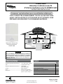
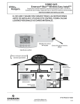
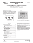
1F98EZ-1621 will accept
up to 3 remote sensors
1
Model 1F98EZ-1641
Includes Comfort/User Interface, Equipment Control
outdoor.
and onefor
Wireless
Remote Sensor
Remote Sensor
(outdoor location)
Wireless Indoor/Outdoor
Remote Sensor
F145RF-1600
Comfort Interface
Equipment Control
Module
NOTE
For heat pump application, outdoor remote sensor can be used
for dual fuel outdoor temperature setting. See Homeowner
26, menu #21.
SPECIFICATIONS
Operating Temperature range: .....
Battery .........................................
Operating Humidity Range...........
Color ............................................
Weight .........................................
Dimensions ..................................
INDEX
0o to 120o
2 “AA” Alkaline Batteries
0 to 85% RH (non-condensing)
Classic White
Weighs less than 0.25 lb.
5”H x 3”W x 2”D
Page
Locate and Mount Remote Sensor
Powering the Remote/Connecting to 1F98EZ-1621
How to Identify the Sensor Number
How to Check Battery Status
Troubleshooting
2
2
3
4
4
4
4
PART NO. 37-7247B
www.white-rodgers.com
www.emersonclimate.com
Replaces 37-7247A
1137
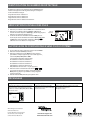
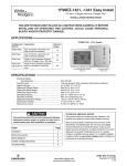
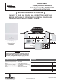
LOCATE AND MOUNT REMOTE SENSOR
IMPORTANT
Before drilling holes for mounting the Remote Sensor, verify the area(s) chosen for mounting allows good wireless
communication to the Equipment Control Module. Place the remote(s) where they will be mounted (but do not drill holes yet)
"$%&
'
location may be required.
Indoor Remote Sensor
Locate Wireless Remote Sensor(s) 5’ Comfort Interface and Remote Sensor location.
Base
Use base to mark mounting hole location on wall. Drill mounting
holes. Remote sensor can be attached to wall after checking operation.
For indoor use, the bracket is optional.
2 “AA” batteries
Mounting
Holes
Outdoor Remote Sensor
If the sensor is going to be used outdoors, clip the indoor/outdoor
jumper labelled W1.
Up
Locate wireless remote sensor setup out of direct sunlight. Direct
!
Mounting
holes
Make sure it is mounted in upright position and in a dry location
"
NOTE
Bracket
mounting
holes
#
"
"
from the mounting surface and away from water buildup.
Clip W1 for
outdoor use
Install mounting bracket to wall at desired location. Outdoor
Remote Sensor can be attached to mounting bracket after
checking wireless operation.
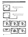
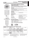
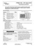
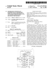
POWERING THE REMOTE/CONNECTING TO 1F98$*+1621
Press Connect
button
Press Connect
button
SYS
HM
HM2
DHM
DHM2
SYS
Connect
DHM2 DHM
R
RC
RH
C
DRY
C
DRY
R
RC
HM2 HM
W/E
W2
Y
Y2
G
O/B
L
SYSTEM L
LED On/Off
POWER
1. $
%&
'
2. Go to Equipment Control and press the Connect button.
Equipment Control Status LED will blink green indicating
3. Press and hold the Connect button located on the inside of
%&'
#'*+%&
amber indicating the sensor number assigned.
1'01
2'02
3' 03
4'04
Equipment Control Module
2
Remote Sensor
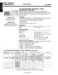
CONFIRM WIRELESS DEVICES ARE COMMUNICATING
1
At the Comfort Interface, press the Menu button once and
release.
2
Press the Connect button once and release. Comfort
Interface display will indicate 1 until (CTL)
control and wireless icon are found. If no communication,
it will show 3
(see Troubleshooting below)
3
Press the Next button once, RS-1 (Remote sensor) should
be displayed if a remote sensor is installed. Temperature
displayed is the temperature at the remote sensor. Press
Next
12RS-2, RS-3,
ORS-4 (outdoor), RAS.
&*
1*
2
Sensor Number
Remote Sensor 1 (if installed)
Remote Sensor 2 (if installed)
Remote Sensor 3 (if installed)
NOTE
Battery icon (
) shows battery
status for each remote.
Outdoor Remote Sensor (if installed)
4
#
1*
2
Press the Run button to return to Home screen.
3
HOW TO IDENTIFY THE SENSOR NUMBER
At the remote sensor, momentarily press the Connect button
3%&
'
number assigned.
1'0 1
2'02
3'03
4'04
HOW TO CHECK BATTERY STATUS
1. Press the Menu button once on the Comfort Interface and
release.
2. Press the Connect button once and release. Comfort Interface
display will indicate 1 until (CTL) control is found.
3. Continue pressing and releasing the Next
the battery icon for all remote sensors (RS 1, RS 2, RS 3 or
ORS). If battery needs to be replaced “Change
will be
displayed for the remote sensor listed on the screen.
Sensor
battery
REMOVE WIRELESS DEVICES FROM THE WIRELESS SYSTEM
1. At the Comfort Interface, press Menu button once.
2. Press the Connect button.
3. Press and release the Next button until the display shows the
+CTL, RS 1, RS 2, RS 3 or ORS.
3%1&*
42
RS 1 (Indoor remote sensor 1)
RS 2 (Indoor remote sensor 2)
RS 3 (Indoor remote sensor 3)
ORS (Outdoor remote sensor 4)
RAS (Return Air Sensor - do not delete)
4. Press and hold the
and
buttons simultaneously to
$
+
press Next !
5. Press the Run button to exit the menu.
TROUBLESHOOTING
Symptom
Possible Cause
Correction Action
The Comfort Interface display will alternately
&
4
Sensor number (RS 1, RS 2, RS 3 or ORS) and
two dashes (--)
&*
4
are located too far apart.
Batteries are dead.
&*
Control Module.
Replace batteries.
5
of Emerson Electric Co.
The Emerson logo is a
"
"
of Emerson Electric Co.
www.white-rodgers.com
www.emersonclimate.com
F145RF-1600
Interior/Exterior inalámbrico
Sensor remoto para 1F98EZ-1621
INSTRUCCIONES DE INSTALACCIÓN
¡Guarde estas instrucciones para uso futuro!
EL NO LEER Y SEGUIR CON CUIDADO TODAS LAS INSTRUCCIONES
ANTES DE INSTALAR O UTILIZAR ESTE CONTROL PODRÍA CAUSAR
LESIONES PERSONALES Y/O DAÑOS MATERIALES.
1F98EZ-1621 acepta
hasta 3 sensores remotos
Model 1F98EZ-1641
Includes Comfort/User Interface, Equipment Control
and one
Wireless Remote Sensor
Sensor remoto
(ubicación externa)
Inalámbrico para
Interior/Exterior
F145RF-1600
Interfaz de confort
Módulo de control
del equipo
NOTA
En aplicaciones de bomba de calor, el sensor remoto externo
puede utilizarse para el ajuste de temperatura externa de doble
combustible. Vea en la Guía del propietario “Opciones del menú
5626, menú N.° 21.
ÍNDICE
ESPECIFICACIONES
Página
Rango de temperatura de transporte: ... 0° a 120°
Pilas ................................................. 2 pilas alcalinas “AA”
Rango de humedad operativa ................ 0 a 85% RH (sin condensación)
Color ................................................. Blanco Clásico
Peso .................................................. Pesa menos de 0.25 lb.
Dimensiones ................................................. 5 pulg. Al x 3 Pulg. An X 2 pulg. P
Ubicación y montaje del sensor remoto
Alimentación del control remoto/Conexión a 1F98EZ-1621
7*
8
se están comunicando
7
9
Cómo comprobar el estado de la pila
Desinstalación de los dispositivos inalámbricos
del sistema inalámbrico
Solución de problemas
N° DE PIEZA 37-7247B
www.white-rodgers.com
www.emersonclimate.com
Reemplaza 37-7247A
1137
2
2
3
4
4
4
4
UBICACIÓN Y MONTAJE DEL SENSOR REMOTO
IMPORTANTE
7
8996
:;
56;
9
9<=>
=
?>@
575
16
"$%
6
:9
;5
Cubierta
Sensor remoto interno
;
*
8
5 pies del suelo en un lugar
*<
7
la ubicación de la interfaz de confort y el sensor remoto.
Base
Deslice la
cubierta fuera
Retire la cubierta sosteniendo la base del sensor remoto y
de la base
presionando la lengüeta en la parte inferior hacia la parte superior.
9
=
;
7
>
<&<
?
2 pilas “AA”
Para uso interno, el soporte es opcional.
@
montajes
Sensor remoto externo
Si el sensor se va a utilizar al aire libre, recorte el puente interior/
!
1.
Arriba
;
*
7
8
<
de la luz solar directa. La exposición directa al sol afectará la
temperatura medida.
@
montajes
#9
7
debajo de un área cubierta como una ventana o un alero.
NOTA
@
montaje de
soporte
!
"
#$
%
&'
Se proporciona un soporte de montaje para mantener el
!<
<<
acumulación de agua.
1 para
uso externo
Instale el soporte de montaje a la pared en la ubicación deseada.
&!<<
?
8
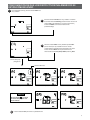
ALIMENTACIÓN DEL SENSOR REMOTO/CONEXIÓN A 1F98$*+1621
Presione el botón
de conexión
1. Instale las pilas para alimentar el sensor remoto. El LED se
iluminará de color rojo y se apagará.
2. Vaya a $9 y presione el botón Connect. El LED
de estado $9 parpadeará de color verde e
8*8
8
3. Presione y mantenga presionado el botón Connect ubicado
*%&
=
parpadear de color verde y, a continuación, suelte el botón.
#
+%&8
8
89
1 disparo ámbar = sensor 1
2 disparos ámbar = sensor 2
3 disparos ámbar = sensor 3
5
9
4 disparos ámbar = sensor exterior 4
Presione el botón
de conexión
SYS
HM
HM2
DHM
DHM2
SYS
Connect
2
HM2 HM
R
RC
RH
C
DRY
C
DRY
R
RC
DHM2 DHM
POWER
W/E
W2
Y
Y2
G
O/B
L
SYSTEM L
LED On/Off
Sensor remoto
CONFIRMACIÓN DE QUE LOS DISPOSITIVOS INALÁMBRICOS SE
ESTÁN COMUNICANDO
1
En la interfaz de confort, presione el botón Menu una
vez y suéltelo.
2
Presione el botón Connect una vez y suéltelo. La interfaz
de confort indicará 1 hasta encontrar el icono de
control (CTL) y de inalámbrico. Si no hay comunicación,
mostrará 3
. (Vea la sección Solución de
problemas abajo)
3
Presione el botón Next una vez; debería aparecer RS-1
(sensor remoto) si hay instalado un sensor remoto.
La temperatura mostrada es la temperatura en el sensor
remoto. Presione Next=
sensores adicionales RS-2, RS-3, ORS-4 (externo), RAS.
*
(obligatorio)
X9
Sensor remoto 1 (si está instalado)
Sensor remoto 2 (si está instalado)
Sensor remoto 3 (si está instalado)
NOTA
El icono de pila =
>muestra
el estado de la pila para cada
sensor remoto.
Sensor remoto externo (si está instalado)
4
Sensor de aire de retorno (obligatorio)
Presione el botón Run para volver a la pantalla Home.
3
CÓMO IDENTIFICAR EL NÚMERO DE SENSOR COMUNICANDO
En el sensor remoto, presione momentáneamente el botón Connect
&%&89
asignado de forma intermitente.
1 disparo ámbar = sensor 1
2 disparos ámbar = sensor 2
3 disparos ámbar = sensor 3
4 disparos ámbar = sensor exterior 4
CÓMO COMPROBAR EL ESTADO DE LA PILA
1. Presione el botón Menu una vez en la interfaz de confort y suéltelo.
2. Presione el botón Connect una vez y suéltelo. La interfaz de confort
indicará 1 (buscando) hasta encontrar el control (CTL).
3. 9
7Next para ver el icono de
la pila para todos los sensores remotos =411, RS 2, RS 3 u 41>. Si
para el sensor
es necesario cambiar la pila, aparecerá “Change
remoto indicado en la pantalla.
Pila del
sensor
RETIRE LOS DISPOSITIVOS INALÁMBRICOS DEL SISTEMA INALÁMBRICOS
1. En la interfaz de confort, presione el botón Menu una vez.
2. Presione el botón Connect.
3. Presione y suelte el botón Next*
*
+CTL, RS 1, RS 2, RS 3 u ORS.
3%17*
2
RS 1 (sensor remoto interno 1)
RS 2 (sensor remoto interno 2)
RS 3 (sensor remoto interno 3)
ORS (sensor remoto externo 4)
RAS (sensor de aire de retorno - no eliminar)
y
4. Presione y mantenga presionado los botones
simultáneamente para eliminar cada dispositivo. Presione
Next*
para eliminar.
5. Presione el botón Run
9
SOLUCIÓN DE PROBLEMAS
Síntoma
Causa probable
758
La pantalla de la interfaz de confort alternará
@
@?
=411, RS 2, RS 341>@
@=[[>
&7*
están demasiado lejos.
Las pilas están agotadas.
*87
*
Reemplace las pilas.
5
7
Emerson Electric Co.
El logotipo de Emerson es una
marca comercial y una marca de
servicio de Emerson Electric Co.
www.white-rodgers.com
www.emersonclimate.com
F145RF-1600
%\]
^\<_\1F98EZ-1621
INSTRUCTIONS D’INSTALLATION
8\~
LIRE ET RESPECTER SOIGNEUSEMENT TOUTES LES INSTRUCTIONS
AVANT L’INSTALLATION OU L’UTILISATION DE CET APPAREIL POUR
PRÉVENIR LES BLESSURES ET LES DOMMAGES MATÉRIELS.
L’appareil 1F98EZ-1621
accepte jusqu’à 3 détecteurs
(
&
Model 1F98EZ-1641
l’intérieur
et 1 détecteur
Includes Comfort/User
Interface, Equipment Control
(
&
and one Wireless Remote Sensor
l’extérieur.
Détecteur à distance
(emplacement extérieur)
Détecteur à distance sans
[
?
\!?
F145RF-1600
Module de confort
Module de régulation
d’équipement
REMARQUE
` 8 \
] ^_\ k @\ \
\ _\ ;[; { ^|
}
(page 26>o 21.
SPÉCIFICATIONS
INDEX
Plage thermique de fonctionnement. ..... -18 °C à 49 °C (0 °F à 120 °F)
Piles ....................................................... 2 piles alcalines « AA »
>[
?
0 à 85 % H.R.
)
Couleur .................................................. Blanc classique
Poids ...................................................... Moins de 113 g (0,25 lb)
Dimensions ............................................ 12,7 cm h. x 7,6 cm l. x 5,1 cm p.
(5 po h. x 3 po l. x 2 po p.)
Page
Détecteur à distance « situer-et-monter »
#
?\]^1F98EZ-1621
*?
?
*
*!
$
??
_?
?
?
*`
?
2
2
3
4
4
4
4
PIÈCE No 37-7247B
www.white-rodgers.com
www.emersonclimate.com
Remplace 37-7247A
1137
%$$4%17$1$4+$+$4
IMPORTANT
78
\]
8\{9{;
8
\
^\9`{
\]
\=^
>8{
8
^
\1
\
\%$"
^
Détecteur à distance d’intérieur
>=?^
^1,5 m du sol, à un
*
?
!?
module de confort et le détecteur à distance.
=?{+=
[|
[`
]
Glissez le
de la base
;
=*+
=%?}!?
?
2 piles « AA »
[
^[
?
+
Trous de
montage
Détecteur à distance d’extérieur
?
?^[!?
+<=
!?
\
?
?
*?1.
Haut
>=?^[?
+
???
Trous de
montage
_?
=*?
?^
+
+}
5
REMARQUE
Trous de
montage du
) *
& &
+&
,+
&
(+&/&
!%&
(
%
?
[!?
^[?
*
[
1
^
[!?
|
!=^[
?
?
%?[!?
}!?
?
ALIMENTATION DU DÉTECTEUR/BRANCHEMENT AU 1F98$*+1621
Enfoncez le
bouton
Connect
Enfoncez le
bouton
Connect
SYS
DRY
HM
HM2
DHM
DHM2
Connect
DHM2 DHM
R
RC
RH
C
SYS
C
DRY
R
RC
HM2 HM
W/E
W2
Y
Y2
G
O/B
L
SYSTEM L
LED On/Off
POWER
1. $=
?%&%
[?
2. Allez à 4\ ^\9
=
Connect12%&%[?\ ^\9
+
*?
?
*
3. Enfoncez et tenez le bouton Connect
?^[
?
?^
+<*[^*&%
+
~=
+&%
^[+
*??
?
1 clignotement ambre = détecteur 1
2 clignotements ambre = détecteur 2
3 clignotements ambre = détecteur 3
4
0?[!?
4
\
^\9
2
Détecteur à distance
CONFIRMATION QUE LES PÉRIPHÉRIQUES SANS FIL
COMMUNIQUENT ENTRE EUX
1
Sur le module de confort, enfoncez une fois le bouton Menu.
2
Enfoncez le bouton Connect
~=5%[
du module de confort indiquera « 1 » (Recherche)
<*[^?
1CTL[
!
[2
}?
+
[
*3
» (Échec). (Consultez la section
?
52
3
Enfoncez le bouton Next1
2RS-1 (Détecteur à
distance 12
[
?^
?%???
&=Next?
?
RS-2, RS-3, ORS-41!?
2RAS
1?[
2
?
[?*
(requis)
Numéro du détecteur
?^
[
?
1 (si installé)
?^
[
?
2 (si installé) ?^
[
?
3 (si installé)
REMARQUE
"^
(
) 9^\
9
\
?^
[!?
1
?2
4
?[
1*
2
Enfoncez le bouton Run1&!?2^[?[
3
IDENTIFICATION DU NUMÉRO DE DÉTECTEUR
#?+=
~=Connect situé sur
[
?
[
%&%
^
*
numéro de détecteur assigné.
1 clignotement ambre = détecteur 1
2 clignotements ambre = détecteur 2
3 clignotements ambre = détecteur 3
4
0?[!?
4
VÉRIFICATION DU NIVEAU DES PILES
1. &=
~=Menu sur le module de confort.
2. &=
~=Connect%[
module de confort indiquera « 1
12<*[^
?
?
13%2
3. =[~Next
[
?^
(RS-1, RS-2, RS-3
ou ORS)
}?+|
}
[
5^5
?
Piles du
détecteur
SUPPRESSION DE PÉRIPHÉRIQUES SANS FIL DU SYSTÈME
1. Sur le module de confort, enfoncez une fois le bouton Menu.
2. Enfoncez le bouton Connect (connecter).
3. &=~=Next1
2<*[^
*[
*[
*=
+
^
CTL, RS 1, RS 2, RS 3 ou ORS.
3%14?
[?*
2
RS 11?^
[
?
1)
RS 21?^
[
?
2)
RS 31?^
[
?
3)
@1?^
[!?
4)
#1?[
2
4. Enfoncez et tenez simultanément les boutons
et
[
#
+=
Next1
2<*[^*[
*[
^
5. Enfoncez le bouton Run1!?2*
DÉPANNAGE
1@
;
8
%[
[+??
du détecteur à distance (RS 1, RS 2, RS 3 ou ORS)
!
%?^
[?*
[[
%
?^
?
[?*
5
[&&
%[&*
de commerce et une marque de
[&&
[