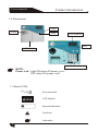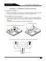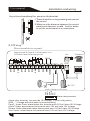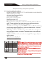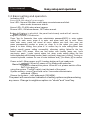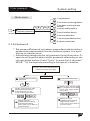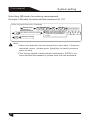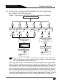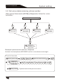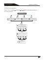
1
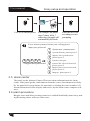
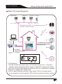
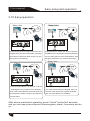
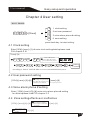
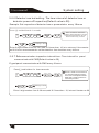
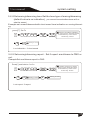
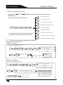
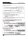
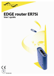
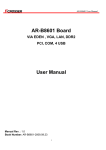
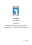
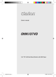
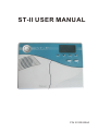
ST-II USER MANUAL
POWER
ARM
DISARM
SOS
ALARM
FIRE
P/N 20100920A0
User manual
Brief
Brief
Dear customer:
Congratulations on purchasing your new security system an thank you for the confidence you have shown in us. You have chosen a high-quality product that has been produced, tested and packed w the greatest care.
Please familiarize yourself with these instructions before attempting to
in stall the security system because prolonged reliable and trouble-free
operation will only been sure if it is fitted properly. We hope your new security system will bring you lasting pleasure.
User manual
Content
Accessories
01
Chapter I Introduction
1.1 Function Introduction
1.2 About panel
1.3 About ICON
Chapter 2 Installation and Connection
2.1 Open the Item Box
2.2 Installation of control panel
2.3 Wiring
2.4 Install wired detector
2.5 Intall wireless detector
Chaptor III Easy setup and operation
3.1 Factory default setting
3.2 Basic setting and operation
3.3 Alarm receiving phones operation
3.4 Remote phone control
3.5 alarm center
3.6 alarm procedure
Alarm Process Diagram
3.7 Telephone line off alarm
3.8 Anti-tamper function
3.9 Event recording and Inquiry
3.10 Easy operation
Chapter 4 User setting
4.1 Clock setting
4.2 User password setting
4.3 Voice alarm phone # setting
4.4 Zone settingeffective or ineffective
Chapter V System Setting
5.1 Setting
5.2 Setting on main menu
5.3 Set password
5.4 Set centre monitoring station
5.5 Set voice alarm receiving phone number
02
02
05
05
06
06
06
07
08
08
09
09
11
12
12
13
13
14
15
15
15
17
18
18
18
18
18
19
19
19
20
22
13
User manual
Content
5.6 System setting options
24
5.7 Enroll wireless device
5.8 Set zone attribution
5.9 Set timing operation
29
32
34
5.10 System maintenance
36
37
Chapter VI alarm and receive alarm
Chapter VII Technical specification
Chapter VIII Maintenance
Chapter IX Limitation of the Products
38
39
39
User manual
Accessories
Accessories
Before installation please check if the whole set including the
components as follow:
One Control panel
One Wireless PIR sensor
One wireless magnetic contact
One remote controllers
One adaptor for control panel
One user manual
8 resistors for 10K
1
User manual
Introduction
Chapter I Introduction
1.1 Function Introduction
1.With voice indication all around the operation.
2.LCD screen indication.
3. Total 32 wireless zones: each zone enable learn code automatically or
enter
code manually on the keypad. The panel compatible with all our made wireless
device.
4. Total 8 wired zone, connect resistor on wired zone terminal to achieve N.O. or
N.C. alarm.
5. Enable enroll total 8 wireless remote, 8 electronic switch, wireless door bell,
and Unlimited for quantity of one way wireless siren.
6. Zone programmable:Before products left factory, will programme alarm type
and delay or instant for each zone as factory default. Use can modify the settings.
7. Enroll wireless device:wirless detector and remote via auto enroll code or enter
address code manually. User enable enroll / delete detector , remote separately
or enroll / delete all simultaneously.
8. Six follow me phone # (voice alarm receiving phone #),two for CMS , four for
private alarm receiving.
9. Clock and event listbuilt-in clock, can be set according to local time.
10. Status inspection functionEnable record and inquiry 120 alarm event messages.
Like the time when happens anti-tamper alarm, detector alarm, tel-line off, arm,
disarm, system setting, battery low voltage etc. And also can inquiry the zone number and alarm type.
11.Password operation :Administrator password mainly for system admini -strator to program the system. User password for user make common operation, like
arm, disarm system, remote control. Both Administrator password and user password can be modified.
2
User manual
Introduction
12. In Central Monitoring System according to quantity of users, user can set 4 ,5
or 6 digit user code.
13. Alarm type auto identifyafter alarm triggered, on the LCD scree will display alarm zone #, alarm type, alarm icon. When connect to CMS,panel will report details
of alarm to CMS.
14. Compatible with CMS machine: support Contact ID. Report alarm to CMS. Report arm/disarm t o CMS optional.
15. Remote control:Enabel via tel phone to achieve remote control system like:arm, disarm , listen to the spot, trigger siren, switch on/off electronic appliance etc.
16. vandal-proof function:If try to cut off the wire between wired detector and panel or cut off the tel line which connect to the panel will make alarm.
17. Anti-tamper function:when someone try to remove panel deliberately panel will
make alarm immediately.
18. Timing arm/disarm: Enable set 4 group time arm/disarm tie.
19. Timing testing: At preset time, panel will send signal to CMS to test the panel
on-line status.
20. Siren :The panel with built-in siren, it can also enroll extension wireless siren.
Both can be settled on/off when alarming.
21.Follow-me number.The pane dials preset follow-me number to report alarm message
22. Voice indication volume enable adjust on the switch.
23. Electronic appliance control:Enable remote inquiry and control the on/off status of electronic appliance. And also enable to switch on/off manually electronic
appliance.
24. Wired/wireless zone real time monitoring:active the real time monitoring function , then if zone with trouble when doing arm/disarm operation the panel will indicate zone
fault.
3
User manual
Introduction
25. Wireless signal repeat function:via our made wireless repeater panel enable to
receive signal from wireless detector from a long distance.
26. Wireless detector low battery real time warningif wireless detector low battery,
it will send signal to panel every one or two hour or when alarm happens,panel will
sound dee dee , and on the LCD screen, low battery icon and zone number will display. And panel will also report to the CMS and preset follow me phone #.
27.Enable the panel siren by pressing the emergency key on the panel or the remote
28. During the alarm receiving procedure the user should enter 4-digit user password to enter. This avoid others without permission to operate the panel.
4
User manual
Product introduction
1.2 About panel
FIRE
POWER
SIREN
ARM
DISARM
SOS
ALARM
FIRE
SOS
LCD SCREEN
LED
POWER
BATTERY BOX
ARM
DISARM
SOS
ALARM
FIRE
NUMERIC KEYBOARD
NOTE :
Power Led : Light ON when AC power is on,
OFF when AC power is off.
1.3 About ICON
[#] OR
1
Key operation
sos
y
m
LCD display
d
disarm
home
away
Speech indication
Cautions
Indication
5
User manual
Installation and wiring
Chapter 2 Installation and Connection
2.1 Open the Item Box
Open the package to check the no accessories missing in the list.
If missing accessories , please contact the distributor.
2.2 Installation of control panel
An obvious feature of the ST-II is that it can be installed without
open it. User just need to connect several wires on the back of
the panel.
1.Remove the bracket on the back of the panel.
Remove the bracket
Push the bracket along the arrow pointed
2.Drill a hole on the wall and fixed the bracket on the wall.
Bracket
Mounting hole
Pivot
Mounting hole
Mounting knockout
6
Usermanual
manual
User
Installation and wiring
As picture showshang the panel on the bracket
1.There sh ould be no large metal goods around
the control.
2.Make sure the distance between the control
panels and detectors is valid. And it is better
to put the control panel in a covert place.
Metal
2.3 Wiring
Wire external device to panel:
Support both N.C and N.O wiring mode. It is
N.O mode in the following picture
10K
10K
10K
TEL
Telephone
10K
10K
10K
10K
10K
12VOUT
GND
Z40
Z39
COM
Z38
Z37
Z36
Z35
COM
Z34
Z33
LINE
-
100 mA
DC 15V
GND
Panic
Alarm
Disarm
Arm
+12v
work voltage 6-12Vsiren
Alarm relay terminal
Alarm relay terminal can provide 12V voltage LED or relay switch
GND "-"voltage when the panel is normal working
Panic Under Panic alarm status,this terminal and +12V will have 12V Voltage.
Alarm: Under alarm status,this terminal and +12V will have 12V Voltage.
Disarm:Under disarmed status,this terminal and +12V will have 12V Voltage.
Arm: Under armed status,this terminal and +12V will have 12V Voltage.
7
User manual
Installation and wiring
2.4 Install wired detector
2.4.1 The wired zone is on bypass status as factory default.If the user need use wired zones, please active them first.When the
wired zone is fault,if user arm system on remote.the user will
hear "zone fault" and The LCD screen will display the fault zL
one number +L .At this time, the system can not be armed by
remote or keypad.
2.4.2 The control panel can power 12v,100mA to detectors.
The max current can power to wired detectors is 100mA.
Do not exceed 100mA, otherwise please adopt extra 12V backup power.
2.5 Intall wireless detector
2.5.1 As the detector's manual saysinstall coded detector in the
area 150m from the control panelPlease test and make sure detector can work with control panel normally.
2.5.2 Wireless distance repeater function: When the installer need to install the wireless accessories from the ST-II panel from a too long distance or there are block between ST-II and accessories, which maybe will cause singal receiving.
Our made wireless reapter will solve this problem throug reapter
the wireless signal distance.
8
User manual
Easy setup and operation
Chaptor III Easy setup and operation
3.1 Factory default setting
Below are factory default of ST-II control panel you can keep the
default setting or modify .
Administrator password:9876
user password:1234
Entry and exist delay:10s
Monitoring time:10s
Cycle dial out to make alarm: 5 times
Ringing times to pick phone call automatically: 7 times after ringing 7 times the panel will take the phone call automatically.
TEL-line cut-off inspection function effective .
Arm/disarm message report to CMS function ineffective. Timing
arm/disarm option ineffective. Auto arm/disarm time, CMS timing inspection time both are zero.
Alarm type of siren whistle during alarm all the time: burglar alarm, perimeter alarm fire alarm, gas leak alarm and user defined alarm type.
All phone number and user code are empty. Siren type of panic
zone is silent
Wired zone is disabled
Wireless zone default set
ZONE
Zone type
Siren
delay
burglar
burglar
on
on
on
on
on
on
on
on
on
burglar
burglar
burglar
burglar
burglar
burlgar
9
Note
Burglar zone Effetive only when system is away armed.
Wireless doorbell zone Chime by wireless zone, sound
Ding~Dong if it is triggered under disarmed status. When the system is armed, this zone will report perimeter
alarm when it it triggered.
Perimeter/Delay zones Effective when the system is
home or away armed.
Gas/Fire/Emergency Always effective when system is
armed or disarmed.
It is not recommended to set the zone siren to be silent
Delay zones: for exit/entry zones
User manual
Easy setup and operation
Considering the convenience of userthe factory default can meet most users' requirement. So, common user only need to proceed easy
setting.
Zone trouble indication
zone+C zone open loop trouble(Wired zones)
zone+O zone shortcut trouble(wired zones), wireless zones is
triggered.
zone+ battery icon
low voltage on detector trouble
zone+L wireless detector loss trouble
<> means of icon displayed on LCD:
Icon
sos
Meaning
Icon
Meaning
Perimeter zone
Enroll devices
Telephone line fault
Disarm
Burglar alarm
Home arm
Panic alarm
Away arm
Help
Alarm
Fire alarm
Adequate battery
voltage
Gas leak
Low battery
Special alarm
Center link failure
Alarm information
is reporting
10
User manual
Easy setup and operation
3.2 Basic setting and operation
Indication LED
Power LED-ON when AC power supply
Arm LED-- Normal ON when under away arm statusnormal blink
when under home arm status.
Alarm LED-- FLASH when alarm happen
Disarm LED-, ON when disarm, OFF when armed.
Before left factory, in whole kit, the panel had already code with all remote,
¡ï
¡
ïBasic contact,
setting PIR detector..
magnetic
.
Press *key for 3seconds, then enter administrator password[9876] to enter system
setting. For each menu press # to enter and press back key to exist. When
.
enter
main menu, panel will sound all menu options one time, then user can
press corresponding number or press up, down to to the option you want, then
press # to enter setting, then press # or confirm key to save setting.When hear
[setting saved] means setting successfully otherwise setting failure.On the key
button under LCD screen, there are four button with function [away arm, hone
arm,inquiry, panic ] under normal status, but when under setting status the four
button separately with following function [back, up(check), down(user), confirm]. The key on
numeric keyboard, numbers for user to enter numbers and [*] for delete, [#] for confirm.
Power on/off--When power on AC, backup battery will get ready auto
matically. When AC power off for 20seconds and enter
¡ï
BasicOperation£º
[1234#] to disarm the system. When AC cut, please switch off the
BAT if you are not
using the system. The BAT switch is at the back of the panel.
System setting-- press [*]and hold on for 3 seconds+administrator
password +[#]key
Disarm the system -- user password +[DISARM]:
The panel will sound voice indication of setting options anytime entering
any menu. Change to neighbour option via "check" and "user"key.
11
User manual
Easy setup and operation
General operation
press and hold on key"0"for 3seconds to enter electroric appliacace setting modeswitch on/off electronic appliance.
press and hold on key"0"for 3seconds to enter electroric appliacace setting modeinquiry on/off status of electronic appliance.
press and hold on key"0"for 3seconds to enter electroric appliacace setting mode set timing on/off electronic appliance.
3.3 Alarm receiving phones operation
When the detector is triggered, the panel will sound alarm and display the triggered zone number and alarm type on the LCD screen. The panel will dial the preset voice numbers if there is no disarming operation during this period.
When the panel dial the preset voice numbers, if there is no operation or not
disable the alarm by pressing1 key, then the panel will continue to call other
voice numbers.
Alarm receiving
Alarm report
POWER
ARM
DISARM
SOS
ALARM
Play pre-record
voice message
FIRE
Enter 4 digit
user password
when prompted
off-hook
Command(on disarm status)
The panel will dial the
preset voice number
3.4 Remote phone control
Alarm occurs, please operate as
following indication
1
2
3
4
5
6
7
0
Cancel the alarm press 1
Check alarm zone press 2
Listen to the spot press 3
Disarm the system press 4
Arm the system press 5
Activate the hoot press 6
Play the zone address
recording press 7
Hand up press 0
User can remote control the system by phone call. After the preset ringing times
then panel will off hook the phone then enter the 4 digit user codes according to
voice prompting and operate as per the voice prompting.
12
User manual
Easy setup and operation
POWER
ARM
DISARM
SOS
ALARM
FIRE
phone
Users to call landline phones
For example, the phone
rings 7 times. After 7
times ring, the panel will
automatically off-hook.
Enter the user code
according to voice
prompting
Focus alarm system welcome your calling, please
input your password.
1
System arm, please press1
2
system disarm, please press2
3
X X X X #
4
4.digital user password
5
6
0
inquiry the system status
please press 3
listen to the spot
control the electrical switch,
please press 5
Inquiry the electrical switch,
please press 6
hang up , please press 0
3.5 alarm center
The panel use the Ademco Contact ID to sent alarm information to the alarm
center. If the panel got the conformation from the center ,then alarmsuccessfully.
Or the panel will repeat alarm ( the max times re-dialing the center number is 5).
Alarm information will be display and resolve by the alarm center computer software.
3.6 alarm procedure
Burglar zones and delay perimeter zones are enabled/disabled by home/away arming/disarming others zones are 24hr zones
13
User manual
Easy setup and operation
Alarm Process Diagram
CMS Number
Telephone
The 1st CMS Number
1st
Telephone
the 5th tel
Mobile
the 6th tel
W
ire
d
3.The panel will dial 1-4 telephones as preset
and the siren will sound
Alarm
software
Alarm situation found,
start to send message
POWER
ARM
DISARM
SOS
110 alarm
centers
ALARM
1.the detectors activated
send alarm information to
alarming center
FIRE
2.sending
alarm information
to CMS
Y
M
N
LCD displaying:
1.Number shows which zone alarm, 33-40 means wired zones, 1-32 means
wireless zones,emergenay help in remote or magmetic contact will be shown
as 00 zone. 00 zone also means the telephone line cut or arm/disarm message.
2.the icon on display also indicate type
3.LED of signal indicates receiving alarm signal, LED of receiving stands
for on progress of receiving alarm, LED of status means the process of alarm
14
User manual
Easy setup and operation
3.7 Telephone line off alarm
If tel-line off check function is effective, when system under arm status,
the siren will whistle as soon as the tel-line cut off. Under disa rm status,
The panel will give voice to tell telephone line cut off for 60 seconds. And if
the tel-line connected again or disarm the system this indication voice will
stop. Otherwise, the siren whistle for 5 minutes.
Y
M
D
3.8 Anti-tamper function.
1. When the control panel receive a message that the wireless magnetic
contact is oping, the panel will solve this as a burglar alarm.(up to the status
code, and alarm type). Just after close the door or windows , and panel
receive the signal of magnetic contact closed. The panel will then solve the
anti-tamper alarm.
2.The display of tamper alarm on the LCD: the zone number , and the status
code: 14 for the icon is burglar.
3.9 Event recording and Inquiry
3.9.1 Event record
Arm, away arm, home arm, disarm, telephone line cut-off , low battery status
and other information can be recorded by the control panel.
When the battery of Wireless detectorinclude magnetic contactis under
voltage, the detector can know when it make timing self-testing, and send
signal to the control panel, then the control panel will give indication voice to
tell detector under voltage, and display on the LCD: low voltage icon, and zone
number and low voltage code(19), eg, 16 19, means no.16 zone with low voltage.
The panel also will send message to the CMS and call the alarm receiving phone
number to remind the system manager and user to change battery.
15
User manual
Easy setup and operation
3.9.2 Event Check
Press the [check] key less than 3sec to inquiry the event recorded. Press
the check key continuously you can get the record one by one chronolo
gically. Press any key to exit.
For example: Burg lar alarm at the fifth wired zone at 8: 30 am 3rd April, 2009
CHECK
Press check key
· À Ç ø
× ´ Ì ¬
Check
Alarm code
01 delay zone
02 Perimeter zone
03 burglar zone
04 emergency zone
05 fire alarm zone
06 gas link zone
07 anti-tamper zone
08 disarm zone
09 arm zone
10 home arm zone
Press check key enter next information display
3.9.3 AC power off and restoration testing function: If the ACpower iswhen
the AC off,the trouble LED will be on the panel will report AC loss to
the CMS,If AC power not restoral in 30min. when the AC is restoral
the panel will send restoral message to CMS
3.9.4 Low voltage inspection function on battery backup of alarm panel when
AC power of panel is OFF,and the back up battery voltage get lower then
6V volt the panel send a message to CMS.
16
User manual
Easy setup and operation
3.10 Easy operation
¡î
Away Arm
POWER
ARM
DISARM
SOS
ALARM
¡î
HomeArm
Arm
¡î
Away
¡ îHOME
POWER
ARM
FIRE
DISARM
SOS
ALARM
FIRE
Press the key for arm away on remote or the
Press the key for home arm on the remote or
keypad, then you hear "the system is arming"
"HOME" key on the keypad, the panel will give
there will be 10 sounds "Dee" to tell you arm
voice to tell system is enter home arming. And
the system successfully
it display home arm icon on the LCD screen.
¡îPanic
POWER
ARM
DISARM
SOS
ALARM
FIRE
Press the panic button on remoter, or press
¡î
Away Arm
¡ îDisarm
POWER
ARM
DISARM
SOS
ALARM
FIRE
press the disarm key on the remote or enter
"help/bypass" key on panel for 3 seconds,
your user password on the keypad, then you
and 10seconds later the panel will dial the
will hear "dee" and voice"system disarmed",
preset phone number. And you can disarm to
then you have disarm successfully.
cancel alarm.
After above-mentioned operation, press "check" button for3 seconds
and you can inquiry record event.like emergency alarm, home arm and so
on.
17
User manual
Easy setup and operation
Chapter 4 User setting
user menu
1
2
3
6
1 2 3 4 +[User]
1 clock setting
2 set user password
3 voice alarm phone # setting
6 zone setting
press back key to exist setting.
4.1 Clock setting
Enter[1234]+[user]+[1]+# enter clock settingdetails please read
P24,chaptor 5.61
Press[*]3s
1 2 3 4 #
0 9
1 #
0 6
0 1
Enter Y.M.D.H.M.
press back key to exit
press confirm key to save
2 0
Y
M
0 9
D
#
Setting
is saved
According to flash of Y.M.D.H.Min on screen,enter 0906012009 by turn
4.2 User password setting
[1234]+[user]+[2]+[#]
enter 4-digit user password,
press back key to exist press +[xxxx]+[#]
enter 4 digit new password
confirm key to confirm.
4.3 Voice alarm phone # setting
Enter [1234]+[user]+[3]+[#] enter voice alarm phone # setting
. for details please read P 23,chaptor 5.5
4.4 Zone settingeffective or ineffective
[1234]+[user]+[6]+[#]
Please choose, press
1 to set on, press 0 to
set off.
enter the zone # from 1-40
to modifypress back key
to exist press confirm key
to confirm.
+[xx]+[#]
+[1]+[#]
18
User manual
System setting
Chapter V System Setting
We will introduce the function setting of ST-II series.
We are not responsible to any problem which caused by user wrong
operation
5.1 Setting
When set system on the keypad, [*] key with both "setting" and
"exit" function. [#] with confirm function.
Every time press a key the panel will sound effective indica -tion
speech.Every time finish one operation the panel will sound corresponding speech indication anyway it is wrong or right operation.
If setting under advanced menu, after finish setting please press
[back] key to back to previous menu to continue other setting.
Press [*] key and hold on for 3 seconds to enter setting status.Enter
administrator password , then press the corresponding key to enter
option setting .Everytime enter correct command please press [#]
to enter the advanced menu.After you enter the advanced menu ,for
user convenience the screen will display the default or the setting
user programmed before .Then the user can enter the setting he want to modify and press [#] key to confirm. If the user do not want to
modify, he can press [#] to keep the former setting.After this operation, the LCD display will back to the status of enter command so that the user can enter next option setting. After you finish all settings,
press back key to exit. If after 5 minutes no any operation the panel
will back to previous menu automatically.
if incorrect operation during setting, you could press[back] key to back to previous menu.
Under disarmed status, Press[*] and hold for 3 seconds then enter
administrator password to enter
. system setting.
5.2 Setting on main menu
Let's learn about how to enter the system and functions.Please set the panel according to following method, and the panel
will keep the memory of your setting until you modify it again.
19
User manual
System setting
Main menu
Please enter administrator password
press[*]for 3 seconds
9 8 7 6 #
*
1
2
3
4
5
6
7
8
1 set password
2 set center monitoring station
3 set alarm receiving phone
number
4 system setting options
5 enroll wireless device
6 set zone attribution
7 set timing arm/disarm time
8 system maintenace
5.3 Set password
* Set passwordPassword includeuser paswordand administrator p*
assworduser passwordwith function todisarm system. It is a private key on remote control.
Adminstrator passwordis the only password to set the system. Please do not forget the administrator password otherwise you can
not operate the system. Press*"(hold * for more than 3 seconds) "
9876#" "1#, then operate according to the speech in dication.
Press[*], then enter administrator
password, then press [1][#]
Set password
[1]modify administrator
password
[2] user password setting
2
1
#
#
Please enter new four-digit
administrator password.
Press back key to exist.
press confirm key to save.
M M M M #
Setting is saved
[1]administrator setting
[2] password setting
Press back key to back to
previous menu.
Please enter new four-digit
user password. Press back
key to exist. press confirm
key to save.
M M M M #
Setting is saved
[1]administrator setting
[2]password setting
Press back key to back to
previous menu.
20
User manual
System setting
Note:Here [M] stands for entering new password
Example 1 Mmodify the administrator password to 1111
Press *key and hold on for 3 seconds
Please enter
password
1
#
9 8 7 6
[1]set administrator password
#
1 #
Please enter new four-digit admini
-strator password.Press [back] key
to exist. press [confirm] or [#] key
to save.
[1] set password
1 1 1 1
Setting is saved
Note :
1.Above are based on correct operation for each step. If incorrect
operation occurs , please press [back] key to back to previous
menu to reset.
2.The factory default of administrator password is [9876].If you
have modified the password, please enter the new password.
21
User manual
System setting
5.4 Set centre monitoring station(please do not set private
phone # as the CMS phone#)
Press [*]3 seconds+[9876#]+[2#],then operate as following.
Set centre monitoring station
1
[1] set number
one CMS
phone number
1 #
2
3
[2] set number
3] set free
two CMS
arm phone number
phone number
3
2 #
Enter phone #
press back key to exit setting
press confirm key to save
press[*] to delete
4
[4] set free
disarm phone
number
4
5
6
[5] set number
one user code
[6] set number
two user code
5
6
Enter 4-8digit user's code
press back key to exit setting
press confirm key to save
press[*] to delete
#
X X X X X
#
X X X X X
#
Setting is saved
Setting is saved
The user code in the CMS setting which is identification code in the
CMS. And the user code in transfer alarm setting is user,identification code between same model panel
After set CMS #,user's code should be also programmed. The panel
adopt 4-8digit algorism user code to meet the demand of different users quantity.It can used for telecom alarm receiving center system.Use 4,5digit user's code,armed/disarmed message will sent to first or
second receiving alarm center phonealarm message will sent to the firstor second recieving alarm center and all of voice receiving alarm.
Use more 6 digit user's code,disarmed /armed message will sent to the second receiving alarm center;the alarm message will sent to the first receiving centerand all of vioce receiving alarm center phone.
22
User manual
System setting
5.5 Set voice alarm receiving phone number
After press[*]3 seconds+[9876#]+[3#]operator follow the voice
indication :
Set voice alarm receiving #
1
[1]set first voice
alarm receiving
phone number.
2
4
3
[2]set second voice
alarm receiving
phone number.
[3]set third voice
alarm receiving
phone number.
[4]set fourth voice
alarm receiving
phone number.
#
Enter phone #
press back key to exit
press confirm key to save
press[*] to delete
Example 2:panel connect with one telephone .
And set the local phone # 87654321 as first voice alarm receiving # :
Press*for 3seconds
Enter system code
Enter phone #
press back key to exit
press confirm key to save
press[*] to delete
Setting is saved
23
9 8 7 6 #
[3]Set voice alarm receiving
#
3 #
0 7 5 5 8 7 6 5 4 3 2 1 #
System back to the previous menu
User manual
System setting
5.6 System setting options
Press[*]3seconds+[9876#]+[4#]operator according voice indication
as following:
Press[ * ]3s
9 8 7 6 #
*
4 #
1
2
3
4
5
6
7
8
9
1clock setting
2entry delay setting
3exit delay setting
4siren time setting
5ringing times setting
6detector loss test setting
7communication test interval time setting
8armed/disarmed indication sound setting
9armed/disarm report setting
5.6.1 clock setting: Set system time administrator june 1st, 2009 20:09.
Operate as :[*]3s[ Administrator password ]>[4][#]>[1]>[Y]>[M]
>[D]>[H]>[M]>[#]
Press[*]3s
*
9 8 7 6 #
4 #
1 #
0 9
0 6
0 1
Y
M
D
Enter Y.M.D.H.M.
press back key to exit
press confirm key to save
2 0
0 9
According to flash of Y.M.D.H.Min on screen,enter 0906012009 by turn
#
Setting is saved
Save setting
Indication: Considering the convenience for user
to know the alarming time, please set the time same
as location time,
24
User manual
System setting
5.6.2 Entry delay setting: the period from system is triggered to panel start alarming(default Value is 10s)
E.gSet the delay time as 9s
Press [*]and hold on for three seconds
*
9 8 7 6 #
4 #
2 #
Administrator password
0 0
9
#
Enter the delay time.
Press back key to exit
press confirm key to save
Setting is saved
You need to enter 3 digit number from 001-255, above example set the entry delayto 9
seconds.
5.6.3 Exit delay setting: the period from user arm to the system armed successfully. This is for user's convenience to exit after arm operation.(
default value is 10s)
Example: Set delay time as 89s
Press[ * ]and hold on for 3s
*
9 8 7 6 #
0 8 9
#
4 #
3 #
Enter the exit delay time .
Press back key to exit
press confirm key to save
Setting is saved
You need to enter 3 digit number from 001-255, above example set the exit delayto 89
seconds.
25
User manual
System setting
5.6.4 Siren time setting: the siren time after panel start alarming(default
value is 5 minutes).
Example: Set the siren time as 15 minutes(It's suggested not to set the siren time more than 15 minutes)
Press [*] and hold on for 3 seconds
*
9 8 7 6 #
1 5
#
4 #
4 #
Enter 0 to 30 minutes siren time
press back to exist.
Press confirm
to save
Setting is saved
Enter 2digit number from 0-30, add 0 if lower than 10, ie to set the time 9 min enter as 09.
5.6.5 Set the ringing time: user dial the phone which connect
to the panel to achieve control the panel remotely(Default value is 7
times).
ExampleSet ringing time as 8
Press [*] and hold on for 3 seconds
*
9 8 7 6 #
0 8
#
4 #
5 #
Enter ringing time. If set
as 0, system wont take the
phone. Press [back] to exit.
press [confirm] or [#]
to save the setting
Setting is saved
Enter 2 digit number from 0 to 99,add 0 if lower than 10, ie to enter 9 times enter 09.
When time set to 00 remote control will be disabled.
26
User manual
System setting
5.6.6 Detector loss test setting: The time interval of detector lose or
detector power-off Inspection(Default value is 00) .
Example: Set inspection of detector loss or power status every 18hours
Press [*] and hold on for 3 seconds
*
9 8 7 6 #
1 8
#
4 #
6 #
Enter 0-24hours interval on
detector loss inspection, 0 for not
inspect.Press back key to exit .
Press confirm key to save.
Setting is saved
Enter 2 digit number from 0 to 24 h, add 0 if lower than 10, ie to set every 9 hours enter
as 09 It is not recommended to set the detection time less than every 4 hours.
5 .6.7 Setcommunication inspection interval time : Time interval for panel
communicate with CMS(Default value is 00)
E.gset panel communicate with CMS every 4 hours.
Press[ * ] and hold on for three seconds
*
9 8 7 6 #
0 4
#
4 #
7 #
Enter 0 to 24 hours interval
on communicationin spection,0 for not inspect.Press
back key to exit .Press confirm key to save.
Setting is saved
Enter 2 digit number from 0-24hours,add 0 if lower than 10, ie to set 9 eneter as 09.
27
User manual
system setting
5.6.8 Set arming/disarming tone:Set the tone type of arming/disarming
(default value is no indication) , you can set here whether alarm will make the sound
Example:set armed/idsarmed with short sound tone indication on arming/disarming.
press[*] for 3s
9 8 7 6 #
*
1
#
4 #
8 #
Choose arm/disarm indication
voice. One no voice, two short sound.
Press back key to exit .Press
confirm key to save.
Setting is saved
1.no indication 2.short sound
5.6.9 Set arming/disarming report : Set if report arm/disarm to CMS or
not.
ExampleSet arm/disarm report to CMS
Press[*] and hold on for 3s
9 8 7 6 #
*
2
#
Setting is saved
4 #
#
9 #
Please choose arm, disarm
report one not report, two report.
Press back key to exit .Press
confirm key to save.
Setting is saved
1.not report 2.report
28
User manual
system setting
5.7 Enroll wireless device
Pressing[*]
indication
[9876#]
[5][#] then operate follow the voice
Press [*] and hold on for 3s
9 8 7 6 #
*
5 #
It's suggested user to enroll detectors/
remote by manually enter the codes
1
"1"Enroll remote
2
"2" enroll detector
3
"3"Enter code of remote
4
"4"Enter code of detector
5
"5" delete remote
6
"6" delete detector
7
"7" Enroll wireless siren
8
"8" Enroll electronic switch
9
"9" delete electronic switch
5.7.1 Enroll remote and delete remote
Exampleenroll #3 remote
1)Auto enrolling:
Press[*] and hold on for 3S
9 8 7 6 #
*
#
3
5 #
1 #
Enter serial number of No.
1 to 8 remote.
Press back key to exit .Press confirm key
to confirm
trigger the remote
Trigger remote
Enroll
successfully
2)Enroll manually
Press[*] and hold on for 3S
9 8 7 6 #
*
3
#
4 3 2 #
29
5 #
3 #
Enter address code of remote.
Press back key to exit .Press confirm key
to save.
Setting is saved
Enter serial number of No.
1 to 8 remote.
Press back key to exit .Press confirm key
to confirm
2 4 3 2 2 2
User can find the 9-digit
address code on the label
sticked on the remote
User manual
system setting
3)Delete remote
Example: delete the #3 remote
press [*] and hold on for 3S
9 8 7 6 #
*
5 #
press back key to exit, press
confirm key to confirm.
#
1 6
5 #
#
enter number 1 to 8 serial number of
remote to delete separately. enter [0]
to delete all , press back key to exit,press confirm key to confirm.
Setting is saved
Save the settings
5.7.2 Enroll and delete detetors
Example: enroll # 16 wireless detector
1Auto enrolling:
Press[*] and hold on for 3S
9 8 7 6 #
*
1
#
61
5 #
trigger the detector
2 #
Enter serial number of No.
1 to 8 remote.
Press back key to exit .Press confirm key
to confirm
Press the anti-tam
per spring
Enroll
successfully
2)Manual enrolling
press [* ] and hold on for 3S
*
9 8 7 6 #
1 6
#
#
5 #
enter 1 to32 serial number of
detector,Press back key to exit .Press
confirm key to confirm
4 #
enter address code of detector ,Press
[back]to exit press [confirm] or [#] to confirm
Setting is saved
1 4 5 2
User can find the 4-digit
address code on the label
sticked on the detector
30
User manual
system setting
3)Example: delete #16 detector
press [*] and hold on for 3S
9 8 7 6 #
*
1 6
# #
5 #
enter number 1 to 32 serial
number of detector to delete seperately. enter [00] to
delete all ,Press back key to
exit Press confirm key to confirm
6 #
press back key to exit,
press confirm key to confirm.
#
Setting is saved
Save the settings
5.7.3 Enroll wireless siren(Example: delete #16 detector)
press [*] and hold on for 3S
9 8 7 6 #
*
#
5 #
7
Enroll siren
Enrolling siren please wait
Press the [SAVE] or [REC] key of the wireless siren NOW till the panel confirms successfully operation, and the siren bleep twice. Press back key to exit.Test the setting was successfully by triggering the siren.
5.7.4
31
User manual
System setting
5.8 Set zone attribution
Press [*]3seconds
indication.
[9][8][7][6]
[#]
[6]then operate follow the voice
Zone attribution setting
2
1
Two, set zone siren type
One ,set zone attribution
#
#
enter one to forty zone number
to modify, press back key to exit,
press confirm key to confirm.
3
enter one to forty zone number
to modify, [00] for emergency button
press back key to exit,
press confirm key to confirm.
2
3
#
#
Chose zone type: 0, disable the zone.1, delay zone.
2,perimeter alarm zone.3, burglar alarm zone.4,
emergency alarm zone.5, fire alarm zone;
6, gas leak alarm;7,keyzone;8,door bell zone
zone.press back key to exit,
press confirm key to confirm.
5
Burglar alarm zone
emergency alarm zone
fire alarm zone
#
6
7
8
Door bell zone
4
Chose zone type siren: one, pedal
point, two pulse tone; three, mute.
Press back key to exit,
press confirm key to confirm.
Key zone
3
gas zone
2
perimeter zone
permanent bypass
1
delay zone
0
2
1
2
#
3
Setting is saved
Note:00 is only for emergency button
of the panel or remote
Setting is saved
Key zones: only for wired zones(33-40), used for access control. when set as
key zones, the burglar function will be disable.
Doorbell zones: only for wireless zones(1-32), when the system is armed,
doorbell zones type is perimeter.
32
User manual
System setting
Wiring method of key zones
Key zones:
1-8 wired zones can be programmed as key
zones, Press * and hold for 3 seconds, enter
administrator password [#]+[6][#]+[1][#]+
[zone number] +[#]+[7][#].
When the zone is programmed as key zone,
the panel status will be same as current key
zones status when power on instead of rest
oring to the status before power off. If there
is more than one key zones, then the panel
status will be the same as the key zones with
maximum number.
User can program the zone type, when the zone is triggered, the panel will report the
preset zone type information of triggered zone to CMS.
Hint: When the zone type is programmed as 0, that means the zone is disabled/bypassed.
33
User manual
system setting
5.9 Set timing operation
Press [*]for 3 seconds
the voice indication.
[9][8][7][6]
[#]
[ 7 ][#]then operate according to
Timing setting
1
One,set # 1 timing
arm, disarm time
2
4
3
Three, set # 3 timing
arm, disarm time
Two, set #2 timing
arm, disarm time
Four, set # 4 timing
arming disarming time
#
enter timing armtime.
It is invalid to set both
hour and minute as zero
1
2
3
4
Minute
Hour
#
Setting is saved. Enter timing
disarm time. It is invalid to set
bothhour and minute as zero
2
2
5
4
Minute
Hour
#
Setting is saved
34
User manual
system setting
Example: Set timing arm at 6:50 AM , timing disarm at 8:35 PM.( Enable set
total 4 groups of timing arm/disarm time)
Press[*] and hold on for 3S
*
9 8 7 6 #
0 6 5 0
#
Setting is saved
#
7 #
1 #
Enter timing disarm time. It is
invalid to set both hour and
minute as zero
enter the timely arming time.
The enter of 0:0 is invalid
2 0 3 5
Save the settings
Hint: 4 groups of timing arm/disarm can be set according
to the schedule of user
35
User manual
system setting
5.10 System maintenance
Press [*]and hold for 3 seconds [9][8][7][6]
the the voice indication.
[#]
[8]then operate follow
system maintenance
1
One, zone
walking testing
#
Enter walking
testing mode,
press back key
to exit, press
confirm
key to confirm
2
Two, communication
testing
#
communication
testing failure
4
Four, delete
event recording.
#
Delete all event
records, press
back key to exit,
press confirm
key to confirm
5
6
Five, back to
factory default
Six, record
alarm address
#
Back to factory
default,press
back key to
exit, press confirm
keyto confirm
#
Panel enter
record mode at
once, and the
time is 15seconds,
t hen willplay the
record speech
7
Seven, play
alarm
address
#
Play the
alarm
address
Walk testing: to test if the detector work normal with alarm panel
Communication testing: To test if the communcation between alarm panel and CMS is normal.
36
User manual
Alarm and receive alarm
Chapter VI alarm and receive alarm
6.1Only the zone type witch is set to be burglar alarming or perimeter alarming is controlled by the operation of away-arming, homearming/ disarming. Other zone types are on the statu of the 24 hours
valid. If spring alarming, the types of burglar alarm, perimeter alarming and selfdefining alarming will alarm after a delay time, but the
other types will immediately alarm through dialup.
6.2The panels adopt Contact ID for the communication protocol
to send the alarming information to the center. If the panel receive the acknowledgement from center, then a successful alarm, if not, the panel will alarm repeatly .alarming information can be displayed and resolved by the software of center computer.
6.3 If trigger the detector alarming, the corresponding panel will
sound warning tone, at the same time, the number of springing zone and alarming type can display on the LCD. If there is no disarming operation during this time, after the warning time, the panel will
dial the receiving alarm phone number. You can hear the voice information of the alarming place while listening the phone. If after 10
S, there is no alarming disposal operation or other self-defining key,
then the alarm process will go on.
When the receiving call is connected and the user operate on the panel, if not press key [2] to release alarming, then the panel will go
on to dial-up alarm with the other set number.
37
User manual
Technical specification
Chapter VII Technical specification
7.1 General data
1 area data: 8 wired areas, 32 wireless zones, 8 remote controllers
2 Zone type: robbing alarm, thief alarm, gas leak alarm, ambulance alarm,
self-defined alarm, fire alarm and boundary alarm events
3 Frequency: 433MHz
4 Signal transmit distance: 100 to 150 meters (open area)
5 Power supply:15V/1A
6.Builtin rechargenble battery: 12V/800mAh
7.Main machine static current: 40mA /12V (exclude wire detector current)
8.Main machine alarming current: <250mA /12V (exclude high siren current)
9.Main machine 12v maximum output current: 100mA for wired detectors
10.Recording time: 10s
11.Frequency: 433MHz0.5MHz
12.The trigger delay of wired zones: 100 ms
13.The method of alarming dial: DTMF
14.DTMF dial frequency variation :< 1.5%
15.Communication Protocol with CMS: Ademco Contact ID
7.2 Physical Performance
Operation temperature range: 320F to 1200F (00C to 450C)
Storage temperature range:-40F to 1400F (-200C to 600C)
Relative humidity: 85% at 30 (860F)
Weight: 650g 250
190
45mm
38
User manual
Maintenance
Chapter VIII Maintenance
8.1 Regular test
D esign of components of the system is to reduce maintenance cost, but still
it is suggested that periodical check may be carried out.
8.2 The cleanliness of control main machine
Main control panel maybe be stained by fingers or covered by dust after using
for a while. Use soft cotton cloth or sponge to clean it. Don't use any lubricant,
liquor such as kerosene, acetone and strong gel which will damage appearance
and the transparency of top window.
ATTENTION: Don't use any lubricant, liquor such as kerosene, acetone and
strong gel which will damage appearance and the top transparency of window.
Chapter IX Limitation of the Products
Although the products is a high standard products, there is also some
limitation of them such as false alarm or no alarm, the reasons may be
below:
Lack of Maintenance. The system needs maintenance and test regularly
test. The sensitive of the detectors may decrease and the siren may not
whistle.
Lack of power supply If no power input and the back up power is not
enough, the panel can not work normally.
Telephone Line False If the telephone line is cut, the panel could not
send alarm signals
Limitation of Smoke Detectors if the smoke is far from the smoke detector,
the detector could not alarm
If the intruder break in through some door or window not monitored, or
some one knows hot to make the system not work,
39
Note
...........................................................................................................
...........................................................................................................
...........................................................................................................
...........................................................................................................
...........................................................................................................
...........................................................................................................
...........................................................................................................
...........................................................................................................
...........................................................................................................
...........................................................................................................
...........................................................................................................
...........................................................................................................
...........................................................................................................
...........................................................................................................
...........................................................................................................
...........................................................................................................
...........................................................................................................
...........................................................................................................
...........................................................................................................
...........................................................................................................
...........................................................................................................
...........................................................................................................
...........................................................................................................
...........................................................................................................
...........................................................................................................
...........................................................................................................
...........................................................................................................
...........................................................................................................
...........................................................................................................
...........................................................................................................
...........................................................................................................
...........................................................................................................
...........................................................................................................