1
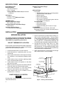
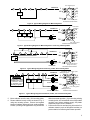
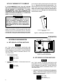
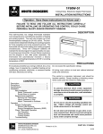
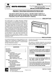
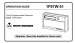
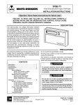
1F97W-71
WHITE-RODGERS
7-Day Electronic Digital Thermostat
INSTALLATION INSTRUCTIONS
Operator: Save these instructions for future use!
FAILURE TO READ AND FOLLOW ALL INSTRUCTIONS CAREFULLY
BEFORE INSTALLING OR OPERATING THIS CONTROL COULD CAUSE
PERSONAL INJURY AND/OR PROPERTY DAMAGE.
DESCRIPTION
This wall-mounted, low voltage thermostat maintains
room temperature by controlling the operation of heating
and cooling systems. The user may program up to four
time/temperature settings per 24 hour period. The thermostat stores independent heating and cooling programs
for each day of the week. The thermostat will store both
heating and cooling programs simultaneously. Three
"AA" Energizer® batteries will maintain the stored program for approximately one year, if incoming power
should fail. If power failure is extensive and the program
is lost, after power restoration, the thermostat will automatically maintain a factory preprogrammed heating temperature of 64°F or a cooling temperature of 82°F.
WHIT
E-RO
DGER
S
PRECAUTIONS
If in doubt about whether your wiring is millivolt, line, or low
voltage, have it inspected by a qualified heating and air
conditioning contractor, electrician, or someone familiar
with basic electricity and wiring.
Description .........................................................
Precautions ........................................................
Specifications .....................................................
Installation ..........................................................
New Installation
Select Thermostat Location
Route Wires to Location
Replacement Installation
Remove Old Thermostat
Attach Subbase to Wall
Attach Thermostat to Subbase
Operation ...........................................................
System Configuration
A. Set Group A Option Switches
B. Set Group B Option Switches
C. Electric Heat Systems
Check Thermostat Operation
Fan Operation
Heating System
Cooling System
Troubleshooting
R
All wiring must conform to local and national electrical
codes and ordinances.
This control is a precision instrument, and should be
handled carefully. Rough handling or distorting components could cause the control to malfunction.
CONTENTS
WHITE-RODGERS DIVISION
EMERSON ELECTRIC CO.
9797 REAVIS ROAD
ST. LOUIS, MISSOURI 63123
Do not exceed the specification ratings.
1
1
2
2
! CAUTION
To prevent electrical shock and/or equipment
damage, disconnect electric power to system, at
main fuse or circuit breaker box, until installation
is complete.
! WARNING
6
Do not use on circuits exceeding specified voltage. Higher voltage will damage control and
could cause shock or fire hazard.
Do not short out terminals on gas valve or primary control to test. Short or incorrect wiring will
burn out thermostat and could cause personal
injury and/or property damage.
PART NO. 37-5091A
Printed in U.S.A.
9139
SPECIFICATIONS
ELECTRICAL DATA
Electrical Rating:
17 to 30v AC 50/60 Hz.
0.05 to 1.5 Amps
1.5 Amps Maximum Total Load (All terminals
combined)
Anticipation:
Heating 2 to 40
Cooling 4 to 40
}
Reference Values
THERMAL DATA
Setpoint Temperature Range:
40° F to 99°F (4°C to 37° C)
Operating Ambient Temperature Range:
32°F to 105°F
Operating Humidity Range:
0 to 90% RH (non-condensing)
Shipping Temperature Range:
-40°F to 150°F
APPLICATIONS
For use with:
• Standard heat/cool, heat-only, or cool-only systems
• Three-wire zone valve systems
• Millivolt systems
• Electric heat systems
• Gas or oil fired systems
• Gas systems with intermittent ignition devices
(I.I.D.) and/or vent dampers
Do not use with:
• Multi-stage systems
• Heat pump systems
• Systems exceeding 30v AC and 1.5 Amps
ACCESSORIES
Remote Sense Kit W. R. Part No. F145-1049
Thermostat Guard W. R. Part No. F29-0198 (clear) or
F29-0238 (opaque)
INSTALLATION
NEW INSTALLATION
You should program the thermostat with batteries
installed before attaching on subbase. See OPERATION GUIDE for programming instructions.
SELECT THERMOSTAT LOCATION
Proper location insures that the thermostat will provide a
comfortable building temperature. Observe the following
general rules when selecting a location:
1. Locate thermostat about 5 ft. above the floor.
2. Install thermostat on a partitioning wall, not on an
outside wall.
3. Never expose thermostat to direct light from lamps,
sun, fireplaces or any temperature radiating equipment.
4. Avoid locations close to windows, adjoining outside
walls, or doors that lead outside.
5. Avoid locations close to air registers or in the direct
path of air from them.
6. Make sure there are no pipes or duct work in that part
of the wall chosen for the thermostat location.
7. Never locate thermostat in a room that normally
warmer or cooler than the rest of the building.
8. Avoid locations with poor air circulation, such as
behind doors or in alcoves.
1. Probe for obstructions in partition before drilling 1/2"
hole in wall at selected location. Take up quarter
round and drill a small guide hole for sighting (see Fig.
1). From basement, drill 3/4" hole in partition floor
next to guide hole. In basementless buildings, drill
1/2" hole through ceiling and into partition from above.
2. Through this hole drop a light chain, or 6" chain
attached to a strong cord. Snag cord in basement
with hooked wire. In basementless buildings, drop
cord through hole in ceiling and down partitioning;
snag cord at the thermostat location.
3. Attach thermostat wire to cord and pull wire through
hole in wall so that 6" of wire protrudes.
1/2" HOLE FOR
THERMOSTAT WIRE
STOUT CORD WITH 6"
CHAIN ATTACHED
BASEBOARD
STRIP MOLDING
APPROXIMATELY
5 FEET
1/4" GUIDE HOLE
FOR SIGHTING
QUARTER ROUND
REMOVED
ROUTE WIRES TO LOCATION
NOTE
All wiring must conform with local and national electrical
codes and ordinances.
2
3/4" HOLE IN FLOOR OF PARTITION
HOOKED WIRE FOR SNAGGING CHAIN
Figure 1. Routing Thermostat Wires
REPLACEMENT INSTALLATION
REMOVE OLD THERMOSTAT
1. Shut off electricity at the main fuse box until installation is complete. Verify power is off with a voltmeter.
2. Remove the front cover of the old thermostat. With
wires still attached, remove wall plate from the wall.
3. If the old thermostat has a wall mounting plate,
remove the thermostat and the wall mounting plate as
an assembly.
4. FOR HEATING ONLY SYSTEMS — Disconnect the
two wires from the old thermostat. Skip steps 5
through 7 below and proceed to ATTACH SUBBASE
TO WALL.
5. FOR HEATING/COOLING SYSTEMS — Before removing wires from old thermostat, identify the terminals that have wires attached on the old thermostat.
Then use Table 1 to identify the type of thermostat you
are replacing. For example, if the old thermostat has
wires attached to terminals R, W, Y, and G, the old
thermostat is a type 5 (note that the old thermostat
may not have wires attached to all the terminals
identified in Table 1).
6. Use the self-adhesive labels enclosed with your
new thermostat to identify the wires attached to
the old thermostat. The labels correspond to the
thermostat type number you identified in step 5 above
(see Table 2). For example, if you determined that the
old thermostat is a type 5, use the labels for the type
5 thermostat (you may not use all the labels for the
type number you've identified if the old thermostat did
not have wires attached to all the terminals).
7. Label each wire as you disconnect it. The labels have
both the old terminal markings and the new terminal
identification. Discard any unused labels. PULL AT
LEAST SIX INCHES OF WIRE OUT OF THE WALL
WHEN YOU DISCONNECT IT - DO NOT ALLOW
THE WIRES TO FALL BACK INTO THE WALL.
TABLE 1. OLD THERMOSTAT IDENTIFICATION
OLD
THERMOSTAT
TYPE
Type
1
Type
2
Type
3
Type
4
Type
5
4
W
RC
Y
G
RH
W
RC
Y
G
M
H
V
C
F
R5
4
Y6
G
R
W
Y
G
TABLE 2. WIRE IDENTIFICATION LABELS
Type
1
New Old New Old New Old New Old New Old
RH 4 W W RC RC Y Y
G G
Type
2
New Old New Old New Old New Old New Old
G G
RH RH W W RC RC Y Y
Type
3
New Old New Old New Old New Old New Old
RH M W H RC V Y C
G F
Type
4
New Old New Old
RH R5 W 4
New Old New Old
Y Y6
G G
Type
5
New Old New Old
RH R W W
New Old New Old
Y Y
G G
PULL STRAIGHT OUT
ATTACH SUBBASE TO WALL
1. Remove the packing material from the thermostat.
Place the fingers of one hand on the center top and
bottom portion of the thermostat. Grasp the subbase
in the other hand on the top and bottom center, and
gently pull straight out (see Fig. 2). The thermostat
has pin and socket connectors. Forcing or prying on
the thermostat will cause damage to the unit.
2. Pull wires through opening in the center of the subbase. DO NOT LET WIRES FALL BACK INTO
WALL.
3. Connect wires beneath terminal screws on subbase
using appropriate wiring schematic (see Figs. 3
through 11).
4. Place subbase over hole in wall and mark mounting
hole locations on wall using subbase as a template.
(Installation instructions continue on page 5.)
OLD THERMOSTAT
TERMINAL IDENTIFICATION
Figure 2. Removing thermostat from subbase
Expansion
Plugs
Connect wires under
terminal screws
S1 S2 S3
Mounting
Hole
6
MV
W
6-pin Connector
RC
G
Activity
Light
Mounting
Hole
Y
RH
3-pin Connector
Pull wires through
this opening
Figure 3. Subbase
3
NOTE
! CAUTION
All wiring diagrams are for typical systems only. Refer to
equipment manufacturers' instructions for specific system wiring information.
To prevent electrical shock and/or equipment
damage, disconnect electrical power at the main
fuse box or circuit breaker until installation is
complete.
From heating system
From 24vAC transformer
THERMOSTAT
6
Y
MV
G
W
RC
W
6
RH
SYSTEM
W
MV
RC
G
Heating
System
Hot
24vAC
Y
RH
120vAC
RH
Neutral
Thermostat Terminal Connections
TRANSFORMER
Figure 4. Typical Wiring Diagram for Heating Only, 2-Wire, Single Transformer Systems
From 24vAC
transformer
From heating system
JUMPER
WIRE
THERMOSTAT
6
Y
MV
G
W
RC
RH
SYSTEM
RED jumper wire (provided with thermostat)
must be connected between thermostat's RH
and RC terminals for proper thermostat operation
with this system.
W
MV
NOTE
Fan
Relay
W
6
Heating
System
RC
G
G
Hot
24vAC
Y
RH
120vAC
RH
From fan relay
CONNECT red jumper
wire (provided)
Neutral
TRANSFORMER
Thermostat Terminal Connections
Figure 5. Typical Wiring Diagram for Heat Only, 3-Wire, Single Transformer Systems
From 24vAC
transformer
THERMOSTAT
6
Y
MV
G
W
RC
RH
SYSTEM
Cooling
System
6
W
MV
RC
G
Fan
Relay
RC
Hot
24vAC
120vAC
G
Y
RH
Neutral
TRANSFORMER
Y
From fan relay
From cooling system
Thermostat Terminal Connections
Figure 6. Typical Wiring Diagram for Cool Only, 3-Wire, Single Transformer Systems
From heating system
CONNECT red jumper
wire (provided)
JUMPER
WIRE
THERMOSTAT
6
MV
Y
G
W
RC
RH
SYSTEM
6
W
W
G
RC
G
MV
NOTE
RED jumper wire (provided with thermostat)
must be connected between thermostat's RH
and RC terminals for proper thermostat operation
with this system.
Cooling
System
Fan
Relay
Heating
System
Hot
24vAC
120vAC
Neutral
TRANSFORMER
RH
RH
From 24vAC
transformer
Y
Y
From fan relay
From cooling system
Thermostat Terminal Connections
Figure 7. Typical Wiring Diagram for Heat/Cool, 4-Wire, Single Transformer Systems
4
From millivolt system
THERMOSTAT
6
Y
MV
G
W
RC
6
RH
SYSTEM
W
W
MV
MV
RC
G
Millivolt
System
Y
RH
From millivolt system
Thermostat Terminal Connections
Figure 8. Typical Wiring Diagram for Millivolt Systems
From millivolt system
From 24vAC
transformer
THERMOSTAT
6
Y
MV
G
W
RC
6
RH
SYSTEM
MV
MV
Millivolt
System
Cooling
System
RC
Fan
Hot
Relay
24vAC
W
W
G
120vAC
Neutral
TRANSFORMER
Y
Y
RH
RC
G
From fan relay
From cooling system
Thermostat Terminal Connections
Figure 9. Typical Wiring Diagram for Millivolt Systems + Cool Only, 3-Wire Systems
From zone valve
THERMOSTAT
Y
MV
G
W
RC
RH
SYSTEM
6 4
Zone
Valve
6
W
6
6
MV
RC
G
5
1 2
Hot
24vAC
120vAC
Neutral
W
Y
RH
RH
From 24vAC transformer
(through zone valve)
TRANSFORMER
Thermostat Terminal Connections
Figure 10. Typical Wiring Diagram for Heat Only, 3-Wire, Zone Valve Systems
THERMOSTAT
6
MV
Y
G
W
RC
RH
SYSTEM
! CAUTION
See HEAT/COOL, 5-WIRE
SYSTEMS section below
to determine whether
this thermostat can be
used with your system.
Hot
Cooling
System
Fan
Relay
Heating
System
24vAC
From 24vAC From heating system
cooling transformer
6
W
MV
G
120vAC
Y
Neutral
HEATING TRANSFORMER
Hot
24vAC
RC
120vAC
Neutral
COOLING TRANSFORMER
RH
W
RC
G
Y
From fan relay
RH
From cooling system
From 24vAC
heating transformer
Thermostat Terminal Connections
Figure 11. Typical Wiring Diagram for Heat/Cool, 5-Wire, Two-Transformer System
5. Move subbase out of the way. Drill mounting holes.
6. Fasten subbase loosely to wall, as shown in Fig. 3,
using two mounting screws. Place a level against
bottom of subbase, adjust until level, and then tighten
screws. (Leveling is for appearance only and will not
affect thermostat operation.) If you are using existing
mounting holes, or if holes drilled are too large and do
not allow you to tighten subbase snugly, use plastic
expansion plugs to secure subbase.
7. Push excess wire into wall and plug hole with a fireresistant material (such as fiberglass insulation) to
prevent drafts from affecting thermostat operation.
5
ATTACH THERMOSTAT TO SUBBASE
IT IS RECOMMENDED THAT YOU SET OPTION
SWITCHES TO DESIRED POSITION BEFORE ATTACHING ON SUBBASE (see OPERATION). IT IS ALSO
RECOMMENDED THAT YOU PROGRAM THE
THERMOSTAT WITH BATTERIES INSTALLED BEFORE ATTACHING ON SUBBASE (see OPERATION
GUIDE for programming instructions).
pin connectors and the plastic snaps lock into place (see
Fig. 12). Be gentle when attaching thermostat. If the
thermostat does not seem to be attaching to the subbase
easily, make sure that the connector pins and plastic
snaps are properly aligned, and that excess wire is
pushed into the wall. Damage to the thermostat may
occur if force is used.
! CAUTION
POWER TO THERMOSTAT MUST BE OFF BEFORE ATTACHING THERMOSTAT TO WALL.
FAILURE TO TURN OFF POWER BEFORE ATTACHING THERMOSTAT MAY CAUSE EQUIPMENT DAMAGE DUE TO RAPID COMPRESSOR
CYCLING.
To attach thermostat to subbase, line up the plastic snap
guides at the bottom of the thermostat and the three
connector pins on the thermostat with the connectors
near the bottom left section of the subbase (when viewed
from the front). Gently pivot the thermostat up until the six
ENGAGE TWO LOWER GUIDES;
PIVOT UP
Figure 13. Attaching thermostat to subbase
OPERATION
SYSTEM CONFIGURATION
6-pin Connector
Batteries
A. SET GROUP A OPTION SWITCHES
W14 W22
NOTE
ANY TIME GROUP B OPTION SWITCHES ARE
CHANGED, THE "AA" BATTERIES MUST BE REMOVED
FOR A MINIMUM OF 2 MINUTES. DO NOT REMOVE
THE BATTERIES WHEN CHANGING GROUP A OPTION SWITCHES.
1. Total Keypad Activity
ON
Switch #1 OFF
Switch #2 OFF
1
(Group A)
(Group B)
Option Switches
3-pin Connector
Figure 13. Back of Thermostat
B. SET GROUP B OPTION SWITCHES
2
NOTE
2. Total Keypad Lockout — All thermostat buttons are
disabled.
ON
Switch #1 ON
Switch #2 OFF
1
2
ANY TIME GROUP B OPTION SWITCHES ARE
CHANGED, THE "AA" BATTERIES MUST BE REMOVED
FOR A MINIMUM OF 2 MINUTES. DO NOT REMOVE
THE BATTERIES WHEN CHANGING GROUP A OPTION SWITCHES.
1. Automatic Changeover (Heating/Cooling Systems
Only) — enables thermostat to automatically switch
between heating and cooling programs to maintain
desired room temperature.
ON
1
6
2
3
Switch #1 ON
Switch #2 OFF
Switch #3 (see step B5)
2. Manual Changeover (Heating/Cooling Systems
Only)
ON
1
2
3
Switch #1 OFF
Switch #2 OFF
Switch #3 (see step B5)
3. Heat Only Systems
ON
1
2
3
Switch #1 OFF
Switch #2 ON
Switch #3 (see step B5)
HEATING SYSTEM
1. Press
SYSTEM
HEAT-OFF-COOL-AUTO
be displayed).
2. Press
to adjust thermostat above room temperature to call for heat. The heating system should
begin to operate.
COOLING SYSTEM
! CAUTION
4. Cool Only Systems
ON
1
2
3
Switch #1 ON
Switch #2 ON
Switch #3 (see step B5)
5. Computed Energy Management Recovery (EMR)
— With EMR enabled, system will be energized
before the next program period begins, to achieve
programmed temperature by the beginning of the
next program period.
ON
1
2
3
Switch #1 (see steps B1–B4)
Switch #2 (see steps B1–B4)
Switch #3 OFF
C. ELECTRIC HEAT SYSTEMS
For central electric heat systems where the blower is
energized by a separate circuit through the fan relay
(meaning that the fan turns on immediately on call for
heat), clip wire W14 on the back of the thermostat (see fig.
13). If the thermostat is energizing electric heat sequencers, DO NOT clip wire W14.
To prevent compressor and/or property damage,
if power to the compressor has been off or
interrupted for more than 1 hour and the outdoor
temperature is below 50°F, DO NOT operate the
system for at least the amount of time the compressor was off! This will allow the compressor
heaters to warm the compressor oils to avoid
damage due to slugging.
1. Press
When checking thermostat, Group B option switches #1
and #2 for automatic changeover must be in the OFF
position. This will allow temporary setting of heat setpoints
above cool setpoints. After system checkout, reset Group
B option switch #1 to ON position if automatic changeover
is desired (see SET GROUP B OPTION SWITCHES).
FAN OPERATION
1. Turn on power to the system. If the heat source has
a standing pilot, be sure to light it.
2. Press
FAN
ON
– AUTO
until FAN ON is displayed. The blower
should begin to operate (this will work only on systems with a G terminal).
3. Press
FAN
ON
– AUTO
until FAN AUTO is displayed. The
blower should stop operating within approximately
one minute.
SYSTEM
HEAT-OFF-COOL-AUTO
until COOL is displayed.
to adjust thermostat below room tem2. Press
perature to call for cool. The blower should come on
immediately, followed by cold air circulation. However, if the red LED on the thermostat front is flashing,
the compressor lockout feature is operating (see
Lockout Bypass Option to temporarily override the
compressor lockout feature during testing).
After the system has been checked and is running properly, determine if automatic changeover is desired (see
SYSTEM CONFIGURATION).
CHECK THERMOSTAT OPERATION
NOTE
until HEAT is displayed (it may already
LOCKOUT BYPASS OPTION
FOR QUALIFIED SERVICE TECHNICIANS’ USE
ONLY. OPERATORS SHOULD NOT USE THIS
FEATURE DUE TO POSSIBILITY OF EQUIPMENT
OR PROPERTY DAMAGE, OR PERSONAL INJURY.
COMPRESSOR SHORT TERM
CYCLE PROTECTION
This thermostat has a built-in short term (5-minute)
time delay. During this 5-minute period, the thermostat will lock out the compressor to allow head pressure to stabilize. If you want to override this feature
while testing thermostat operation, simply press
and
VIEW
PRGM
VIEW
TEMP
buttons at the same time at initial startup.
DO NOT USE THE LOCKOUT BYPASS OPTION
UNLESS THE COMPRESSOR OIL HEATERS HAVE
BEEN OPERATIONAL FOR 6 HOURS AND THE
SYSTEM HAS NOT BEEN OPERATIONAL FOR AT
LEAST 5 MINUTES.
7
Refer to the OPERATION GUIDE if you need additional
information on thermostat operation.
TROUBLESHOOTING
Refer to the Question & Answer section of the OPERATION GUIDE for information on troubleshooting the thermostat.
If you need further information about this product, please write to:
WHITE-RODGERS
Division of Emerson Electric Co.
9797 Reavis Road
St. Louis, MO 63123
ATTN: Technical Service Department
WARRANTY INFORMATION
THIS WARRANTY STATEMENT SUPERSEDES ALL WARRANTY
STATEMENTS DATED PRIOR TO MARCH 1, 1988.
White-Rodgers Division of Emerson Electric Co. (“Seller”) warrants that its products purchased for resale (the “Products”) will be
free from defects in material and workmanship under normal use
and service for a period of twelve (12) months from date of
installation. Seller’s obligation under this warranty, and Purchaser’s
exclusive remedy for the breach thereof, shall be limited to, at
Seller’s option, Seller’s replacement of any defective Product
F.O.B. Seller’s factory, or Seller’s issuance of a credit in the amount
of the purchase price of such Product for resale as described
below. Seller shall have the option of requiring the return of any
defective Product, transportation charges prepaid, before recognizing any claim. This warranty shall not apply to any Product (1)
which has been repaired or altered outside Seller’s factory or by
other than Seller in any manner so as, in Seller’s judgement, to
affect its serviceability or proper operation; (2) which has been
subjected by persons other than Seller to improper handling,
operation, maintenance, repair or alteration; or (3) which has been
subjected to misuse, negligence, or accident.
This warranty extends only to persons or organizations who
purchase the Products for resale. THE FOREGOING CONSTITUTES SELLER’S SOLE RESPONSIBILITY UNDER THIS WARRANTY, AND PURCHASER’S EXCLUSIVE REMEDY FOR
BREACH THEREOF. EXCEPT AS OTHERWISE EXPRESSLY
SET FORTH IN THIS AGREEMENT, THERE ARE NO OTHER
WARRANTIES, EXPRESS OR IMPLIED, WHETHER OF MERCHANTABILITY, FITNESS FOR A PARTICULAR PURPOSE, OR
OTHERWISE. SELLER SHALL NOT BE LIABLE FOR ANY
SPECIAL, INDIRECT, INCIDENTAL OR CONSEQUENTIAL DAMAGES IN CONNECTION WITH THE SALE, RESALE OR USE OF
THE PRODUCTS.
Complete warranty information and instructions for replacing/
returning warranty products can be found in the White-Rodgers
Product Catalog, or by telephoning or writing to:
White-Rodgers Division
Emerson Electric Co.
9797 Reavis Road
St. Louis, Missouri 63123-5329
(314) 577-1300
WARRANTY INFORMATION FOR CONSUMERS
When you purchase a White-Rodgers Division product, it is typically for replacement of a device which has failed on existing
residential or commercial equipment, or a component of new
equipment purchased for modernization.
While our warranty does not extend to you, your contractor or
dealer is protected by a one-year product warranty from WhiteRodgers. Your supplier can rely on a nearby White-Rodgers
wholesaler for prompt credit or replacement.