1
ML-2
TECHNICAL EDUCATION
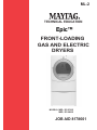
Epic™
FRONT-LOADING
GAS AND ELECTRIC
DRYERS
MODELS: MED / GD 9700S
MED / GD 9600S
JOB AID 8178601
FORWARD
This Maytag Job Aid, “Epic™ Front-Loading Gas and Electric Dryers,” (Part No. 8178601), provides
the In Home Service Professional with information on the installation, operation, and service of the
Epic™ Front-Loading Gas and Electric Dryers. It is to be used as a training Job Aid and Service
Manual. For specific information on the model being serviced, refer to the “Use and Care Guide,”
or “Tech Sheet” provided with the dryer.
The Wiring Diagrams used in this Job Aid are typical and should be used for training purposes only.
Always use the Wiring Diagram supplied with the product when servicing the unit.
GOALS AND OBJECTIVES
The goal of this Job Aid is to provide detailed information that will enable the In Home Service
Professional to properly diagnose malfunctions and repair the Maytag Epic™ Front-Loading Gas
and Electric Dryers.
The objectives of this Job Aid are to:
• Understand and follow proper safety precautions.
• Successfully troubleshoot and diagnose malfunctions.
• Successfully perform necessary repairs.
• Successfully return the Gas or Electric Dryer to its proper operational status.
WHIRLPOOL CORPORATION assumes no responsibility for any repairs made
on our products by anyone other than Authorized In Home Service Professionals.
Copyright © 2006, Whirlpool Corporation, Benton Harbor, MI 49022
- ii -
TABLE OF CONTENTS
Page
GENERAL ............................................................................................................................................ 1-1
Safety First ...................................................................................................................................... 1-1
Model & Serial Number Designations ............................................................................................. 1-2
Model & Serial Number Label And Tech Sheet Locations ............................................................. 1-3
Specifications .................................................................................................................................. 1-4
Maytag Dryer Warranty ................................................................................................................... 1-5
INSTALLATION INFORMATION ......................................................................................................... 2-1
Installation Instructions ................................................................................................................... 2-1
DRYER USE ........................................................................................................................................ 3-1
COMPONENT ACCESS ....................................................................................................................... 4-1
Component Locations ..................................................................................................................... 4-1
Removing The Electronic Control Board......................................................................................... 4-2
Removing The Console & The Touchpad Subassembly ................................................................ 4-4
Removing The Door Switch ............................................................................................................ 4-6
Removing The Thermal Fuse, Thermistor, Drive Motor, & Belt Switch .......................................... 4-7
Removing The Heater, The High-Limit Thermostat, & Thermal Cutoff
(Electric Dryers Only) ................................................................................................................ 4-10
Removing The Belt, Drum, & Rollers ............................................................................................ 4-12
Removing The Drum Light Socket ................................................................................................ 4-15
Removing The Moisture Sensor ................................................................................................... 4-17
Removing The Burner Assembly, Flame Sensor, And High-Limit Thermostat
(Gas Dryers Only) ..................................................................................................................... 4-18
COMPONENT TESTING ...................................................................................................................... 5-1
Heater ............................................................................................................................................. 5-1
Drive Motor...................................................................................................................................... 5-2
Thermal Fuse .................................................................................................................................. 5-3
Thermistor ....................................................................................................................................... 5-4
Thermal Cutoff (Electric Dryers Only) ............................................................................................. 5-5
Door Switch ..................................................................................................................................... 5-6
Gas Burner Coils ............................................................................................................................. 5-7
Burner Ignitor .................................................................................................................................. 5-7
Flame Sensor .................................................................................................................................. 5-8
High-Limit Thermostat ..................................................................................................................... 5-8
DIAGNOSTICS AND TROUBLESHOOTING ...................................................................................... 6-1
Diagnostics...................................................................................................................................... 6-1
Diagnostic Guide ....................................................................................................................... 6-1
Display Fault/Error Codes ......................................................................................................... 6-2
Diagnostic Tests........................................................................................................................ 6-2
Troubleshooting .............................................................................................................................. 6-4
Troubleshooting Guide .............................................................................................................. 6-4
Troubleshooting Tests .............................................................................................................. 6-4
WIRING DIAGRAMS ............................................................................................................................ 7-1
Electric Dryer .................................................................................................................................. 7-1
Gas Dryer ........................................................................................................................................ 7-1
- iii -
— NOTES —
- iv -
GENERAL
SAFETY FIRST
Your safety and the safety of others is very important.
We have provided many important safety messages in this Job Aid and on the appliance. Always
read and obey all safety messages.
This is the safety alert symbol.
This symbol alerts you to hazards that can kill or hurt you and others.
All safety messages will follow the safety alert symbol and either the word
“DANGER” or “WARNING.” These words mean:
DANGER
You can be killed or seriously injured if you don’t
immediately follow instructions.
WARNING
You can be killed or seriously injured if you don’t
follow instructions.
All safety messages will tell you what the potential hazard is, tell you how to reduce the chance
of injury, and tell you what can happen if the instructions are not followed.
1-1
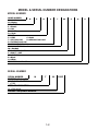
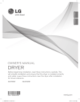
MODEL & SERIAL NUMBER DESIGNATIONS
MODEL NUMBER
MODEL NUMBER
M
E
D
PRODUC T G ROUP
M = Maytag
FUEL TYPE
E = Electric
G = G as
PRODUC T
D = Dryer
S ERIES
5 = L EAP
6 = Oasis
7 = 24" Front L oad
8 = Mid L ine Front L oad
9 = Full S ize Front L oad
PRIC E POINT L EVEL (1-9)
TRADE PARTNER ID
00 = Branded
YEAR OF INTRODUC TION
S = 2006, T = 2007
C OL OR C ODE
B = Black
Q = White
ENG INEERING C HANG E
9
7
00
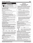
SERIAL NUMBER
S ERIAL NUMBER
M
DIVIS ION = Marion, OH
YEAR OF PRODUC TION
T = 2006
WEEK OF PRODUC TION
26 = 26th Week
PRODUC T S EQUENC E NUMBER
T
26
1-2
13227
S
Q
0
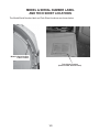
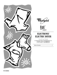
MODEL & SERIAL NUMBER LABEL
AND TECH SHEET LOCATIONS
The Model/Serial Number label and Tech Sheet locations are shown below.
Model & Serial Number
Label Location
Tech Sheet Location
(Behind Lower Access Panel)
1-3
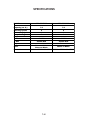
SPECIFICATIONS
12345
3 1!3 #$ !%
2
4
7
#
3$!!
14367389
1436738
9
9
"
"
&
'
( )
*#+
,!
.!'/
.!*0
"1234(92'4"556(23
1-4
&
'
( )
*#+
,!'/!'/
"1234(92'4"556(23
123425 67897824 7 12 78 299 2 6 2882 43
12345367489 9 3 4 67762 5
For one year from the date of purchase, when this major appliance is operated and maintained according to instructions attached to or
furnished with the product, Maytag Corporation or Maytag Limited (hereafter “ Maytag”) will pay for Factory Specified Parts and repair
labor to correct defects in materials or workmanship. Service must be provided by a Maytag designated service company. This lim ited
warranty applies only when the major appliance is used in the country in which it was purchased.
9 3 4 65 64 988421 465417
Service calls to correct the installation of your major appliance, to instruct you how to use your major appliance, to replace or repair
house fuses or to correct house wiring or plumbing.
Service calls to repair or replace appliance light bulbs, air filters or water filters. Those consumable parts are excluded fro m warranty
coverage.
Repairs when your major appliance is used for other than normal, single-family household use.
Damage resulting from accident, alteration, misuse, abuse, fire, flood, acts of God, improper installation, installation not in
accordance with electrical or plumbing codes, or use of products not approved by Maytag.
Any food loss due to refrigerator or freezer product failures.
Replacement parts or repair labor costs for units operated outside the United States or Canada.
Pickup and delivery. This major appliance is designed to be repaired in the home.
Repairs to parts or systems resulting from unauthorized modifications made to the appliance.
Expenses for travel and transportation for product service in remote locations.
The removal and reinstallation of your appliance if it is installed in an inaccessible location or is not installed in accordan ce with
published installation instructions.
Replacement parts or repair labor costs when the major appliance is used in a country other than the country in which it was
purchased.
9869 374149 893 4 67762 93489 9 6 91241473 3 93
1
CUSTOMER'S SOLE AND EXCLUSIVE REMEDY UNDER THIS LIMITED WARRANTY SHALL BE PRODUCT REPAIR AS PROVIDED
HEREIN. IMPLIED WARRANTIES, INCLUDING WARRANTIES OF MERCHANTABILITY OR FITNESS FOR A PARTICULAR PURPOSE,
ARE LIMITED TO ONE YEAR OR THE SHORTEST PERIOD ALLOWED BY LAW. MAYTAG SHALL NOT BE LIABLE FOR INCIDENTAL
OR CONSEQUENTIAL DAMAGES. SOME STATES AND PROVINCES DO NOT ALLOW THE EXCLUSION OR LIMITATION OF
INCIDENTAL OR CONSEQUENTIAL DAMAGES, OR LIMITATIONS ON THE DURATION OF IMPLIED WARRANTIES OF
MERCHANTABILITY OR FITNESS, SO THESE EXCLUSIONS OR LIMITATIONS MAY NOT APPLY TO YOU. THIS WARRANTY GIVES
YOU SPECIFIC LEGAL RIGHTS AND YOU MAY ALSO HAVE OTHER RIGHTS, WHICH VARY FROM STATE TO STATE OR PROVINCE
TO PROVINCE.
1
Outside the 50 United States and Canada, this warranty does not apply.
Contact your authorized Maytag dealer to determine if an other
warranty applies.
If you need service, first see the “ Troubleshooting ” section of the Use & Care Guide. After checking “Troubleshooting, ” additional help
can be found by checking the “ Assistance or Service” section or by calling Maytag. In the U.S.A., call . In Canada, call
.
5/06
!!"4#$%&4'(()4*+,4-(./4&*0!&4&0%"4#(1!#$!/42(/42.#./!4
/!2!/!+3!45(.44."/(5%,!4"/((24(24"./3$*&!4(/4%+&#*00*#%(+4
,*#!42(/4%+6*//*+#-4&!/5%3!
Write down the following information about your major appliance
to better help you obtain assistance or service if you ever need it.
You will need to know your complete model number and serial
number. You can find this information on the model and serial
number label located on the product.
123425673829999999999999999999999999999999999999999999999999999
52 99999999999999999999999999999999999999999999999999999999
726782599999999999999999999999999999999999999999999999999
2467825 99999999999999999999999999999999999999999999999999
253467825 99999999999999999999999999999999999999999999999999
53 26 32 99999999999999999999999999999999999999999999999999
1-5
123456654172 123489 41723
4
7 Gather the required tools and parts before starting installation.
Read and follow the instructions provided with any tools listed
here.
Flat-blade screwdriver
Vent clamps
#2 Phillips screwdriver
Caulking gun and
compound (for installing
new exhaust vent)
Adjustable wrench that
opens to 1" (2.5 cm) or
hex-head socket wrench
(for adjusting dryer feet)
Tin snips (new vent
installations)
Wire stripper (direct wire
installations)
¼" nut driver
(recommended)
Level
Tape measure
Are you placing the dryer on a pedestal? You have the option of
purchasing a pedestal separately for this dryer. You may select a
15.5" (39.4 cm) pedestal. This pedestal will add to the total height
of the dryer for a total height of approximately 53.5" (135.9 cm).
For a garage installation, you will need to place the pedestal at
least 3.5" (8.9 cm) above the floor.
Remove parts packages from dryer drum. Check that all parts are
included.
7862 44 6
To order, call the dealer from whom you purchased your dryer or
refer to the Assistance or Service section of this manual.
6789
12345467892649
12345
Do not use leveling legs if installing the dryer on a
pedestal.
Check local codes. Check existing electrical supply and venting.
See “Electrical Requirements” and “Venting Requirements”
before purchasing parts.
For close-clearance installations between 31.5" (80.01 cm)
and 37" (93.98 cm), see Plan Vent System section for
venting requirements.
17
White
WHP1500SQ
Black
WHP1500SB
3
Are you planning to stack your washer and dryer? To do so, you
will need to purchase a Stack Kit.
To order, call the dealer from whom you purchased your dryer or
refer to the Assistance or Service section of this manual. Ask
for Part Number 8541503.
111111234
56276819
Mobile home installations require metal exhaust system hardware
available for purchase from the dealer from whom you purchased
your dryer. For further information, please refer to the Assistance
or Service section of this manual.
2-1
12345627 89 6 9 975
9 6 97627
1234546
2627 44 111111
99 4
4!9 459 64 47 "42 # 3$ 4
42679# 44 2 9 %
&439 9 45 945 '( 673$9 )*+ 3 , 4!2"9 5$9 22
2 4 4 49 675445627%
-46 9 52 2 2 347 9 5 67 945$# 92627# 2 6 9%
2 6799
*Most installations require a minimum 5" (12.7 cm) clearance
behind the dryer for the exhaust vent with elbow. See Venting
Requirements.
A location that allows for proper exhaust installation. See
Venting Requirements.
A separate 30-amp circuit.
7544562743672 93994 942 3295675445627
If you are using a power supply cord, a grounded electrical
outlet located within 2 ft (61 cm) of either side of the dryer.
See Electrical Requirements.
The following spacing dimensions are recommended for this
dryer. This dryer has been tested for spacing of 0" (0 cm)
clearance on the sides and rear. Recommended spacing should
be considered for the following reasons:
Additional spacing should be considered for ease of
installation and servicing.
A sturdy floor to support the total dryer weight of 200 lbs
(90.7 kg). The combined weight of a companion appliance
should also be considered.
A level floor with a maximum slope of 1" (2.5 cm) under entire
dryer. If slope is greater than 1" (2.5 cm), install Extended
Dryer Feet Kit, Part Number 279810. Clothes may not tumble
properly and automatic sensor cycles may not operate
correctly if dryer is not level.
Additional clearances might be required for wall, door and
floor moldings.
For a garage installation, you will need to place the dryer at
least 18" (46 cm) above the floor. If you are using a 10"
(25.4 cm) pedestal, you will need to place the pedestal at
least 9" (22.9 cm) above the floor. With a 13" (33 cm)
pedestal, you will need to place the pedestal at least
6" (15.2 cm) above the floor. With a 15.5" (39.4 cm) pedestal,
you will need to place the pedestal at least 3" (7.6 cm) above
the floor.
For closet installation, with a door, minimum ventilation
openings in the top and bottom of the door are required.
Louvered doors with equivalent ventilation openings are
acceptable.
Do not operate your dryer at temperatures below 45 ºF (7ºC). At
lower temperatures, the dryer might not shut off at the end of an
automatic cycle. This can result in longer drying times.
The dryer must not be installed or stored in an area where it will
be exposed to water and/or weather.
Check code requirements. Some codes limit, or do not permit,
installation of the dryer in garages, closets, mobile homes or
sleeping quarters. Contact your local building inspector.
75445627394 4739
The location must be large enough to allow the dryer door to
open fully.
2-2
Additional spacing should be considered on all sides of the
dryer to reduce noise transfer.
Companion appliance spacing should also be considered.
52 79 32 759 675445627 9 27
111
*Required spacing
12345678946 22 68397 7 5 7392
123455262727896
96
946
9468 3968483 962 8
For cabinet installation, with a door, minimum ventilation
openings in the top of the cabinet are required.
12 3456784697 7 67 7 46576
2 675 794786
*Required spacing
**For side or bottom venting, 0" (0 cm) spacing is allowed.
5544573 72345678946 22 68397 7 5 73975546 2
*Required spacing
**For side or bottom venting, 0" (0 cm) spacing is allowed.
12345526727896
9468 396848232 27848
3 4 2 896
94689 8 3278 28 6787288
The dimensions shown are for the recommended spacing.
111
12 6 66576
2 3456784697 7 67 7
46576
*Required spacing
**For side or bottom venting, 0" (0 cm) spacing is allowed.
*Required spacing
*Required spacing
2-3
123456782967 7
4 42574 55 42764696 A 4-wire power supply connection must be used when the
appliance is installed in a location where grounding through
the neutral conductor is prohibited. Grounding through the
neutral is prohibited for (1) new branch-circuit installations,
(2) mobile homes, (3) recreational vehicles, and (4) areas
where local codes prohibit grounding through the neutral
conductors.
This dryer is suitable for mobile home installations. The
installation must conform to the Manufactured Home
Construction and Safety Standard, Title 24 CFR, Part 3280
(formerly the Federal Standard for Mobile Home Construction
and Safety, Title 24, HUD Part 280) or Standard CAN/CSA-Z240
MH.
1234567829674 55 427646
12345678393
Metal exhaust system hardware, which is available for
purchase from your dealer.
Special provisions must be made in mobile homes to
introduce outside air into the dryer. The opening (such as a
nearby window) should be at least twice as large as the dryer
exhaust opening.
56 45 64696 5
354
3
Use a UL listed power supply cord kit marked for use with
clothes dryers. The kit should contain:
A UL listed 30-amp power supply cord, rated 120/240 volt
minimum. The cord should be type SRD or SRDT and be at
least 4 ft (1.22 m) long. The wires that connect to the dryer
must end in ring terminals or spade terminals with upturned
ends.
A UL listed strain relief.
123
747276243454 43
4
3
536
365
To contact a qualified electrical installer.
To be sure that the electrical connection is adequate and in
conformance with the National Electrical Code, ANSI/NFPA
70-latest edition and all local codes and ordinances.
The National Electric Code requires a 4-wire power supply
connection for homes built after 1996, dryer circuits involved
in remodeling after 1996, and all mobile home installations.
A copy of the above code standards can be obtained from:
National Fire Protection Association, One Batterymarch Park,
Quincy, MA 02269.
To supply the required 3 or 4 wire, single phase, 120/240 volt,
60 Hz., AC only electrical supply (or 3 or 4 wire, 120/208 volt
electrical supply, if specified on the serial/rating plate) on a
separate 30-amp circuit, fused on both sides of the line. A
time-delay fuse or circuit breaker is recommended. Connect
to an individual branch circuit. Do not have a fuse in the
neutral or grounding circuit.
123456756869 8 67 12
Then choose a 4-wire power supply cord with ring or spade
terminals and UL listed strain relief. The 4-wire power supply
cord, at least 4 ft (1.22 m) long, must have four 10-gauge copper
wires and match a 4-wire receptacle of NEMA Type 14-30R. The
ground wire (ground conductor) may be either green or bare. The
neutral conductor must be identified by a white cover.
123
43
4
3
536
365
Do not use an extension cord.
If codes permit and a separate ground wire is used, it is
recommended that a qualified electrician determine that the
ground path is adequate.
56 45726 42
To properly install your dryer, you must determine the type of
electrical connection you will be using and follow the instructions
provided for it here.
This dryer is manufactured ready to install with a 3-wire
electrical supply connection. The neutral ground conductor is
permanently connected to the neutral conductor (white wire)
within the dryer. If the dryer is installed with a 4-wire electrical
supply connection, the neutral ground conductor must be
removed from the external ground connector (green screw),
and secured under the neutral terminal (center or white wire)
of the terminal block. When the neutral ground conductor is
secured under the neutral terminal (center or white wire) of
the terminal block, the dryer cabinet is isolated from the
neutral conductor.
If local codes do not permit the connection of a neutral
ground wire to the neutral wire, see ?Optional 3-wire
connection ? section.
2-4
23456756869 8 67 2
Then choose a 3-wire power supply cord with ring or spade
terminals and UL listed strain relief. The 3-wire power supply
cord, at least 4 ft (1.22 m) long, must have three 10-gauge copper
wires and match a 3-wire receptacle of NEMA Type 10-30R.
123
77
678336
3
6
Power supply cable must match power supply (4-wire or 3-wire)
and be:
Flexible armored cable or nonmetallic sheathed copper cable
(with ground wire), protected with flexible metallic conduit. All
current-carrying wires must be insulated.
10-gauge solid copper wire (do not use aluminum).
To supply the required 4 wire, single phase, 120/240 volt,
60 Hz., AC only electrical supply on a separate 30-amp
circuit, fused on both sides of the line. A time-delay fuse or
circuit breaker is recommended. Connect to an individual
branch circuit.
99
11For a grounded, cord-connected dryer:
This dryer must be grounded. In the event of malfunction or
breakdown, grounding will reduce the risk of electric shock
by providing a path of least resistance for electric current.
This dryer uses a cord having an equipment-grounding
conductor and a grounding plug. The plug must be plugged
into an appropriate outlet that is properly installed and
grounded in accordance with all local codes and ordinances.
This dryer is equipped with a CSA International Certified
Power Cord intended to be plugged into a standard 14-30R
wall receptacle. The cord is 5 ft (1.52 m) in length. Be sure
wall receptacle is within reach of dryer ?s final location.
11For a permanently connected dryer:
This dryer must be connected to a grounded metal,
permanent wiring system, or an equipment-grounding
conductor must be run with the circuit conductors and
connected to the equipment-grounding terminal or lead on
the dryer.
123456756869 8 67 12
Do not use an extension cord.
If you are using a replacement power supply cord, it is
recommended that you use Power Supply Cord Replacement
Part Number 9831317. For further information, please reference
the service numbers located in the ?Assistance or Service?
section of this manual
"9#
Improper connection of the equipmentgrounding conductor can result in a risk of electric shock.
Check with a qualified electrician or service representative
or personnel if you are in doubt as to whether the dryer is
properly grounded. Do not modify the plug on the power
supply cord: if it will not fit the outlet, have a proper outlet
installed by a qualified electrician.
99
11For a grounded, cord-connected dryer:
This dryer must be grounded. In the event of malfunction or
breakdown, grounding will reduce the risk of electric shock
by providing a path of least resistance for electric current.
This dryer is equipped with a cord having an equipmentgrounding conductor and a grounding plug. The plug must
be plugged into an appropriate outlet that is properly
installed and grounded in accordance with all local codes
and ordinances.
1!119
1234567482 93
763 3 5 8 88 2
1234546
1234567482 9
4
"9#
Improper connection of the equipmentgrounding conductor can result in a risk of electric shock.
Check with a qualified electrician or service representative
or personnel if you are in doubt as to whether the dryer is
properly grounded. Do not modify the plug provided with the
dryer: if it will not fit the outlet, have a proper outlet installed
by a qualified electrician.
886
1!119
2 75 8 6 3 6 5235
87263 5 48 6325 7 385
6 3234567482 4 57 663 77275
To contact a qualified electrical installer.
To be sure that the electrical connection is adequate and in
conformance with the Canadian Electrical Code, C22.1-latest
edition and all local codes. A copy of the above codes
standard may be obtained from: Canadian Standards
Association, 178 Rexdale Blvd., Toronto, ON M9W 1R3
CANADA.
2-5
1234567482 9
3457
3629 6
2
76345763
1234546
1234546
9 9 1 ##9 8 9 92
9 869 6 9892
96 9 !9 9 "# 98968 96 2
$ 96 968 9 %&69 969 9' 6 969
698 %8(9'2
) 9 %#99 !9 9' 6 !9 969 6
#99 # 96 2
$ 96 9# 3 87 9 6 9#
3 698 %# 8'2
59987 6#&69 88 98968 96 2
89 6 986 96&* 9* 98968 & "2
9 9 9 869 4 9 87 2
9 869 6 9892
96 9 !9 9 "# 98968 96 2
$ 96 968 9 %&69 969 9' 6 969
698 %8(9'2
) 9 %#99 !9 9' 6 !9 969 6
#99 # 96 2
$ 96 9# 3 87 9 6 9#
3 698 %# 8'2
59987 6#&69 88 98968 96 2
89 6 986 96&* 9* 98968 & "2
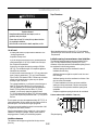
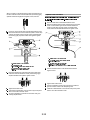
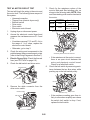
12 Disconnect power.
32 Remove the hold-down screw and terminal block cover.
1
23
789 185 5!1791"
3 #
515
7
1758 9 1
16"
1
"5 3 9"157
3
123 456789 1
3 758 9 1
8 6
8
67
8185
3 5 7581 58
851758 9 1
185
3 58 9 1
5819 1
185
1
7
1
Put power supply cord through the strain relief. Be sure
that the wire insulation on the power supply cord is inside
the strain relief. The strain relief should have a tight fit with
the dryer cabinet and be in a horizontal position. Do not
further tighten strain relief screws at this point.
185
6 1
789 185 5!1791"
42 Install strain relief.
56789 1 9 87 6 989
Remove the screws from a 1/2" (1.9 cm) UL listed strain
relief (UL marking on strain relief). Put the tabs of the two
clamp sections into the hole below the terminal block
opening so that one tab is pointing up and the other is
pointing down, and hold in place. Tighten strain relief
screws just enough to hold the two clamp sections
together.
2-6
1234567869 5 26
562 6 54 5
645 2
Unscrew the removable conduit connector and any
screws from a 1/2" (1.9 cm) UL listed strain relief (UL
marking on strain relief). Put the threaded section of the
strain relief through the hole below the terminal block
opening. Reaching inside the terminal block opening,
screw the removable conduit connector onto the strain
relief threads.
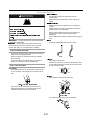
465 2 62 63# 6$%56$8
&63#6 446'56
5 2 (628
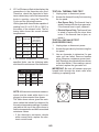
)62615 2 4-wire receptacle
(NEMA Type 14-30R)
A UL listed,
120/240 volt
minimum,
30-amp, dryer
power supply
cord*
4-wire connection:
Power supply cord
4-wire direct
A fused
disconnect or
circuit breaker
box*
4-wire connection:
Direct Wire
3-wire receptacle
(NEMA type 10-30R)
A UL listed,
120/240 volt
minimum,
30-amp, dryer
power supply
cord*
3-wire connection:
Power supply cord
3-wire direct
A fused
disconnect or
circuit breaker
box*
3-wire connection:
Direct Wire
123456789
12 3456789 4 6 6 4 6
2 6 4 94 6 45 8 9 6 64 2 8 4 4 48
Put direct wire cable through the strain relief. The strain
relief should have a tight fit with the dryer cabinet and be
in a horizontal position. Tighten strain relief screw against
the direct wire cable.
/
3
1 4 6789
*If local codes do not permit the connection of a cabinet-ground
conductor to the neutral wire, go to ?Optional 3-wire
connection ? section.
123456789
68 49 7 9365778957
!86 A 4-wire connection is required for mobile homes
and where local codes do not permit the use of 3-wire
connections.
Now complete installation following instructions for your type
of electrical connection:
5 (recommended)
12 4 4 48 4 !"#1 $4 %&'3(
2 6 2 )6 6 *2 !48 6 "2 84 45 8 4 4 +2 ,- %2. 5( /0 4 8 4 4
)2 3 45 8 5 (if 4-wire is not available)
" Remove center silver-colored terminal block screw.
7 Remove neutral ground wire from external ground conductor
screw. Connect neutral ground wire and the neutral wire
(white or center wire) of power supply cord under center,
silver-colored terminal block screw. Tighten screw.
2-7
123456789
68 49 7 4568 7345677
789
A 4-wire connection is required for mobile homes
and where local codes do not permit the use of 3-wire
connections.
Direct wire cable must have 5 ft (1.52 m) of extra length so dryer
can be moved if needed.
Strip 5" (12.7 cm) of outer covering from end of cable, leaving
bare ground wire at 5" (12.7 cm). Cut 1 1/2" (3.8 cm) from
3 remaining wires. Strip insulation back 1" (2.5 cm). Shape ends
of wires into a hook shape.
12 3456789 7 8 85 7 76 556 86 5 8 31 7 8 76 6 76 68 6 5
68567 67 76 56789 ! 762
"2 #68567 67 76 56789 ! 76
#2 6579 7 8 76
2 6579 76 $56 7 68567 76%
32 &' $(2) % 56 5798 76 6
12 Connect ground wire (green or bare) of power supply cord to
When connecting to the terminal block, place the hooked end of
the wire under the screw of the terminal block (hook facing right),
squeeze hooked end together and tighten screw, as shown.
external ground conductor screw. Tighten screw.
2 Remove center silver-colored terminal block screw.
2 Remove neutral ground wire from external ground conductor
screw. Connect neutral ground wire and place the hooked
end (hook facing right) of the neutral wire (white or center
wire) of direct wire cable under the center screw of the
terminal block. Squeeze hooked ends together. Tighten
screw.
12 3456789 7 8 85 7 76
"2 *7 8 76 $ 7668 7 976% 67 + 7
#2 ' $(2) % 56 5798 76 6
2 #68567 67 76 56789 ! 76
32 6579 7 8 76
,2 6579 76 $56 7 68567 76%
32 Connect the other wires to outer terminal block screws.
Tighten screws.
42 Tighten strain relief screws.
52 Insert tab of terminal block cover into slot of dryer rear panel.
Secure cover with hold-down screw.
62 You have completed your electrical connection. Now go to
“Venting Requirements.”
2-8
12 3456789 7 8 85 7 76 556 86 5 8 31 7 8 76 6 76 68 6 5
68567 67 76 56789 ! 762
"2 #68567 67 76 56789 ! 76
#2 6579 7 8 76
2 6579 76 $56 7 68567 76%
32 &' $(2) % 56 5798 76 6
12 Connect ground wire (green or bare) of direct wire cable to
external ground conductor screw. Tighten screw.
2 Loosen or remove center silver-colored terminal block screw.
2 Connect neutral wire (white or center wire) of power supply
cord to the center, silver-colored terminal screw of the
terminal block. Tighten screw.
12 3456789 7 8 85 7 76
2 7 8 76 7668 7 976 67 7
2 2 ! "# 56 5798 76 6
$2 68567 %67& 76 567!89 ' 76
32 (6579 7 8 76
)2 (6579 76 *56 7 68567 76
32 Place the hooked ends of the other direct wire cable wires
under the outer terminal block screws (hooks facing right).
Squeeze hooked ends together. Tighten screws.
42 Tighten strain relief screw.
52 Insert tab of terminal block cover into slot of dryer rear panel.
Secure cover with hold-down screw.
62 You have completed your electrical connection. Now go to
“Venting Requirements.”
123456789
68 49 7 936577895
789 9 9 98 9 9 9 9 92
12 3456789 7 8 85 7 76
2 (6579 7 8 76
2 68567 %67& 76 567!89 ' 76
$2 (6579 76 *56 7 68567 76
32 2 ! "# 56 5798 76 6
12 Connect the other wires to outer terminal block screws.
Tighten screws.
32 Tighten strain relief screws.
42 Insert tab of terminal block cover into slot of dryer rear panel.
Secure cover with hold-down screw.
52 You have completed your electrical connection. Now go to
“Venting Requirements.”
123456789
68 49 74568 73456
789 9 9 98 9 9 9 9 92
Direct wire cable must have 5 ft (1.52 m) of extra length so dryer
can be moved if needed.
Strip 31/2" (8.9 cm) of outer covering from end of cable. Strip
insulation back 1" (2.5 cm). If using 3-wire cable with ground
wire, cut bare wire even with outer covering. Shape ends of wires
into a hook shape.
1
12 +&76 76659 6 (3,1 56 -&+-.
2 +&76 2 (6579 7 8
$2 /96 567!89 5* 5786 68
32 2 ! "# 56 5798 76 6
)2 .8 567!89 2 (6579 *56 7 68567 76
2-9
When connecting to the terminal block, place the hooked end of
the wire under the screw of the terminal block (hook facing right),
squeeze hooked end together and tighten screw, as shown.
123456789
4 95663456
89 9 9
2
12 Remove center silver-colored terminal block screw.
32 Remove neutral ground wire from external ground conductor
screw. Connect neutral ground wire and the neutral wire
(white or center wire) of power supply cord/cable under
center, silver-colored terminal block screw. Tighten screw.
12 Loosen or remove center silver-colored terminal block screw.
32 Place the hooked end of the neutral wire (white or center wire)
of direct wire cable under the center screw of terminal block
(hook facing right). Squeeze hooked end together. Tighten
screw.
12 3456789 7 8 85 7 76
2 6579 7 8 76
2 68567 67 76 56789 76
2 6579 76 56 7 68567 76
32 !2" #$ 56 5798 76 6%
12 3456789 7 8 85 7 76
2 68567 67 76 56789 76
2 6579 7 8 76
2 6579 76 56 7 68567 76
32 !2" #$ 56 5798 76 6%
&2 '7 88 (95 656786 ) 9 *9 %6 6 65798
42 Connect the other wires to outer terminal block screws.
Tighten screws.
42 Place the hooked ends of the other direct wire cable wires
under the outer terminal block screws (hooks facing right).
Squeeze hooked ends together. Tighten screws.
52 Tighten strain relief screws.
62 Connect a separate copper ground wire from the external
52 Tighten strain relief screw.
62 Insert tab of terminal block cover into slot of dryer rear panel.
ground conductor screw to an adequate ground.
72 Insert tab of terminal block cover into slot of dryer rear panel.
Secure cover with hold-down screw.
Secure cover with hold-down screw.
72 You have completed your electrical connection. Now go to
“Venting Requirements.”
2-10
1234536 72895 2 234
5
1234546
For best drying performance, rigid metal vents are
recommended.
Rigid metal vent is recommended to avoid crushing and
kinking.
Flexible metal vents are acceptable only if accessible for
cleaning.
!"
Flexible metal vent must be fully extended and supported
when the dryer is in its final location.
# $ %
& ' %
Remove excess flexible metal vent to avoid sagging and
kinking that may result in reduced airflow and poor
performance.
& ( %
( ' '
Do not install flexible metal vent in enclosed walls, ceilings or
floors.
( %
7 To reduce the risk of fire, this dryer MUST BE
EXHAUSTED OUTDOORS.
1234567869
Observe all governing codes and ordinances.
The dryer exhaust must not be connected into any gas vent,
chimney, wall, ceiling or a concealed space of a building.
45° elbows provide better airflow than 90 ° elbows.
9 536325 4536234 42
Clean lint from the entire length of the system and make sure
exhaust hood is not plugged with lint.
333333333333333
Replace any plastic or metal foil vent with rigid or flexible
heavy metal vent.
33333333333 Review Vent system chart. Modify existing vent system if
necessary to achieve the best drying performance.
Use clamps to seal all joints.
Exhaust vent must not be connected or secured with screws
or other fastening devices that extend into the interior of the
duct. Do not use duct tape.
45 5 32234 42 1234 42 5
Use a heavy metal vent. Do not use plastic or metal foil vent.
4" (10.2 cm) heavy metal exhaust vent and clamps must be
used.
Recommended hood styles are shown here.
12
3456789
1234567839
3
3
3 3 Vent products can be purchased from your dealer or by
calling Maytag Services. For more information, see the
?Assistance or Service? section of this manual.
12
3456789
12
3456789
7 3 3
7 3 3
The angled hood style (shown here) is acceptable.
12
3456789
6 2
51789
2-11
74326 3 74 7322374
An exhaust hood should cap the vent to keep rodents and
insects from entering the home.
Exhaust hood must be at least 12" (30.5 cm) from the ground
or any object that may be in the path of the exhaust (such as
flowers, rocks or bushes, snow line, etc.).
This dryer can be converted to exhaust out the right side, left side
or through the bottom. If you prefer, you may contact your local
dealer to have the dryer converted.
1234546
Do not use an exhaust hood with a magnetic latch.
123453647869 9
95547
7
97
6725 46797 9 7 57
56
7
72746 7 9
Moisture damage to woodwork, furniture, paint, wallpaper,
carpets, etc.
Housecleaning problems and health problems.
4674
586479676 7567 7596757 67
55 9
1234 5647 89 76
696 3 74 7322374796
6
!"#"7$ 6%
!"&7$'
59 6466 3 74 7322374
Typical installations vent the dryer from the rear of the dryer.
Other installations are possible.
7 %
75475
7664(
467 57557 667 9 4
46766
4
75
23 $515751
1
23 45 675
93 83 9
3 17 1
3 43 91
51 7
#3 91
7
9746 7 976 7
7171 83 %71
51517171 3 8
171 717 17
3 !71 717"75 61
597
754764 57 9)4(
1"
7"17
27643764 7322374 2 6263346
Venting systems come in many varieties. Select the type best for
your installation. Two close-clearance installations are shown.
Refer to the manufacturer?s instructions.
23 &75'7'
717
83 *75"
2-12
1 )
71 1( 1 71
1
71
12345
27383258
The following kits for close clearance alternate
installations are available for purchase. Please see the
“Assistance or Service” section of this manual to order.
Over-the-Top Installation:
12345
43
Side and bottom exhaust installations have a 90 º turn
inside the dryer. To determine maximum exhaust length, add one
90º turn to the chart.
Periscope Installation (For use with dryer vent to wall vent
mismatch):
18 8 3!78 8
Part Number 4396037 - 0" (0 cm) to 18" (45.72 cm)
mismatch
Part Number 4396011 - 18" (45.72 cm) to 29" (73.66 cm)
mismatch
Part Number 4396028
Part Number 4396014 - 29" (73.66 cm) to 50" (127 cm)
mismatch
6789 7 8 8 The exhaust vent must be securely fastened to a noncombustible
portion of the mobile home structure and must not terminate
beneath the mobile home. Terminate the exhaust vent outside.
"# 88$
$
%& 8$
$
' & $ 8
( 8# 8 8
64 ft (20 m)
36 ft (11 m)
58 ft (17.7 m)
28 ft (8.5 m)
' & $ 8
( 8# 8 8
54 ft (16.5 m)
31 ft (9.4 m)
48 ft (14.6 m)
23 ft (7 m)
' & $ 8
( 8# 8 8
44 ft (13.4 m)
27 ft (8.2 m)
38 ft (11.6 m)
19 ft (5.8 m)
' & $ 8
( 8# 8 8
35 ft (10.7 m)
25 ft (7.6 m)
29 ft (8.8 m)
17 ft (5.2 m)
)
' & $ 8
( 8# 8 8
27 ft (8.2 m)
23 ft (7 m)
21 ft (6.4 m)
15 ft (4.6 m)
123245672892738
3
Select the route that will provide the straightest and most
direct path outdoors.
73
Plan the installation to use the fewest number of elbows and
turns.
Use the fewest 90° turns possible.
12345
292 67 2
4#98 8 *8 & + , $
-8 8 787 8 8 $ $!8
( 8 $ 9 8 9. 8 /!
Bend vent gradually to avoid kinking.
Use the following Vent system chart to determine type of vent
material and hood combinations acceptable to use.
273 325
1234546
When using elbows or making turns, allow as much room as
possible.
123245672892738 273 8 782 87222848238
4678 2445 72
73
Install exhaust hood. Use caulking compound to seal exterior
wall opening around exhaust hood.
Connect vent to exhaust hood. Vent must fit inside exhaust
hood. Secure vent to exhaust hood with 4" (10.2 cm) clamp.
Run vent to dryer location. Use the straightest path possible.
See ?Determine vent path? in ?Plan Vent System.? Avoid 90º
turns. Use clamps to seal all joints. Do not use duct tape,
screws or other fastening devices that extend into the interior
of the vent to secure vent.
Do not use vent runs longer than those specified in
the Vent system chart. Exhaust systems longer than those
specified will:
Shorten the life of the dryer.
Reduce performance, resulting in longer drying times and
increased energy usage.
The Vent system chart provides venting requirements that will
help to achieve the best drying performance.
2-13
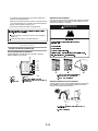
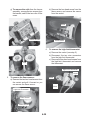
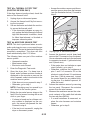
To protect the floor, use a large flat piece of cardboard from
the dryer carton. Place cardboard under the entire back edge
of the dryer.
Firmly grasp the body of the dryer (not the console panel).
Gently lay the dryer on the cardboard. See illustration.
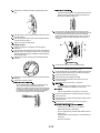
12 Examine the leveling legs. Find the diamond marking.
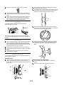
62 Lift and pull forward on the door so that the keyhole clears
the screw head. Remove the door.
12 Lay the dryer door on a flat, protected surface with the inside
door assembly facing up. Remove the last screw from Step 1.
Remove the 2 screws holding the handle to the door.
32 Screw the legs into the leg holes by hand. Use a wrench to
finish turning the legs until the diamond marking is no longer
visible.
42 Place a carton corner post from dryer packaging under each
of the 2 dryer back corners. Stand the dryer up. Slide the
dryer on the corner posts until it is close to its final location.
Leave enough room to connect the exhaust vent.
12324 56726
Check the levelness of the dryer. Check levelness first
side to side, then front to back.
32 Remove the 6 screws to release the outer door assembly
from the inner door assembly (see illustration). It is important
that you remove only the 6 indicated screws.
If the dryer is not level, prop up the dryer using a wood block.
Use a wrench to adjust the legs up or down and check again for
levelness.
89
2
2
52 Using a 4" (10.2 cm) clamp, connect vent to exhaust outlet in
42 Lift the inner door assembly off of the outer door assembly.
Unsnap the handle from the outer door assembly, move it to
the other side, and snap in. Set the outer door assembly
aside.
dryer. If connecting to existing vent, make sure the vent is
clean. The dryer vent must fit over the dryer exhaust outlet
and inside the exhaust hood. Check that the vent is secured
to exhaust hood with a 4" (10.2 cm) clamp.
62 Move dryer into its final location. Do not crush or kink vent.
12 (On gas models) Check that there are no kinks in the flexible
gas line.
32 Once the exhaust vent connection is made, remove the
corner posts and cardboard.
23262 5996 You can change your door swing from a right-side opening to a
left-side opening, if desired.
2932 2996
52 Open the dryer door. Remove the 4 screws that hold the door
hinge on the front panel of the dryer. Loosen, but do not
remove, the screw with the top keyhole opening last (second
from the top).
23262 2 2 26 2
52 Place the inner door, screw head side up, on the work
surface.
62 Remove the 4 screws that hold the hinge to the door.
12 34564
72 389 8 946 8 62
2 345649884
2-14
12 Remove the 2 screws that hold the handle bracket to the
89
door.
7 9 2
Peel off the label located on the opposite side of the door
opening covering the hinge mounting holes. Apply the
label over the original hinge holes.
52 Insert a screw in the second opening from the top of the
hinge opening and partially tighten. Hang the door by placing
the top hinge keyhole over the second screw head and
tighten the screw. By putting this screw in first, the door will
hang in place while you insert and tighten the remaining
4 screws.
32 Move hinge to the other side and reattach with the 4 screws
removed in Step 2.
42 Move handle bracket to the other side and reattach with the
2 screws removed in Step 3.
52 Set the inner door assembly aside.
123456788349 6 2
62 Check for fingerprints on the glass. Clean the glass if
necessary.
72 Place the inner door assembly into the outer door assembly.
Align the hinge in the opening on the side. To fit correctly, the
inside door assembly edge is completely inside the outside
door assembly edge.
12 Reassemble the inner and outer door assemblies with the
6 screws.
12 3456478994
2 34564
2 6477467427
2 Close the door and check that it latches securely.
8262 456788763 4
62 Check that all parts are now installed. If there is an extra part,
go back through the steps to see which step was skipped.
32 Replace the 2 handle screws for the door handle of the door
assembly.
42 Remove the plug strip or label.
89 6 9 92
72 Check that you have all of your tools.
12 Dispose of/recycle all packaging materials.
32 Check the dryer’s Final location. Be sure the vent is not
crushed or kinked.
Use a small flat-blade screwdriver to remove the plug
strip in the door opening. Slide the head of the
screwdriver under the top portion of the plug strip, being
certain not to scratch the dryer surface. Lift up. Repeat in
the middle and at the bottom. Remove the plug strip in
the door opening and insert in the opposite side.
42 Check that the dryer is level. See Level Dryer.
52 9 282 2
For power supply cord installation, plug into a grounded
outlet. For direct wire installation, turn on power.
!"
Plug into a grounded 4 prong outlet. Turn on power.
2 Remove any protective film or tape remaining on the dryer.
#2 Read Dryer Use.
$2 Wipe the dryer drum interior thoroughly with a damp cloth to
remove any dust.
6%2 Set the dryer on a full heat cycle (not an air cycle) for
20 minutes and start the dryer.
& 9 " ' 9 99( ) )* 9 & '
Controls are set in a running or “On” position.
Start button has been pushed firmly.
Dryer is plugged into a grounded outlet and/or electrical
supply is on.
Household fuse is intact and tight, or circuit breaker has
not tripped.
Dryer door is closed.
2-15
12342 564
67897
3 9 199
1234546
1234546
!"
# $% ! " & !' ( ) ' * $! "!!9
+ "! () ( ( &! (" ()
$% ,& $! *()-9
.! $ * ( ! ! "('
' ! $!9
.! !"
4 *(! ! & 9
+ "! () ( ( &! (" $ ,") /) -9
5 ) $ ' !%%!' ! % "!"
( ! % ) 2! 9
.! $ * ( ! ! "(
! $!9
12345467
To reduce the risk of fire, electric shock, or injury to
persons, read the IMPORTANT SAFETY INSTRUCTIONS before
operating this appliance.
Follow these basic steps to start your dryer. Please refer to
specific sections of this manual for more detailed information.
This manual covers several different models. Your dryer may not
have all of the cycles and features described.
Clean lint screen before or after each cycle. See Cleaning
the Lint Screen.
Place laundry in dryer and shut door.
Rotate the dial to select either an Automatic or Manual Cycle
then press the CONTROL ON button. The preset settings and
drying time for the cycle chosen will be displayed.
Select DRYNESS LEVEL to adjust how dry you want the
load to be. The time displayed is an estimated length of
the cycle based on the Dryness Level selected. As the
cycle runs, the control senses the dryness of the load and
adjusts the time automatically for the selected Dryness
Level.
1
89
9
9
2 4 7 Time is not adjustable for Automatic Cycles. Pressing
Point the dial to an Automatic Cycle.
the Manual Dry Time (- or +) buttons will cause a triple beep,
indicating that the time cannot be changed.
Press the EXTRA CARE feature button if this option is
desired.
3-1
: Drying will continue from where the cycle was interrupted
Press the CYCLE END SIGNAL button to set signal
volume to desired level.
Press and hold HOLD TO START button until dryer starts
(about 1 second).
Once an Automatic cycle has started, the Extra Care feature
and the Cycle End Signal level can be adjusted. Press the
OFF button twice to stop the dryer and clear the settings,
allowing you to select another cycle and Dryness Level.
12345672897 4
362 3 3 This feature allows you to lock your settings to avoid unintended
use of the dryer. You can also use the Control Locked feature to
avoid unintended cycle or option changes during dryer operation.
42
This feature improves drying performance with Auto Moisture
Sensing Plus, which advances the cycle as moisture is
extracted from clothing. A thermistor (electronic temperature
sensor) and moisture sensing strips in the dryer drum help
measure the amount of moisture in the clothes as they
tumble. An electronic control determines the load type to help
save time, avoid overdrying, and increase the accuracy of the
end dryness level. After the first 5 minutes of an automatic
cycle, the estimated time display will adjust based on the
approximate load size, cycle, dryness level selected and
amount of moisture left in the clothes. When the clothes have
reached approximately 80% of the dryness level selected, the
estimated time display will adjust again, showing the final
drying time. Auto Moisture Sensing Plus takes the guesswork
out of drying time and enhances fabric care.
2464949694
5
Press and hold the CYCLE END SIGNAL button for 3 seconds.
The control is locked when a single beep is heard and the Control
Locked status light is on.
When the dryer is off, it is not necessary to press the Control
On button before activating the Control Locked feature.
3963
Press and hold the CYCLE END SIGNAL button for 3 seconds to
turn this feature off.
When the dryer is running and Control Locked is on, the
dryer can be stopped by pressing the Off button, but can ?t be
restarted until the control is unlocked.
567 6 54
Press MANUAL DRY TIME (- or +) buttons until the desired
drying time is displayed. Tap - or + and the time will change
by 1-minute intervals. Press and hold - or + and the time will
change by 5-minute intervals. The initial time displayed is the
actual drying time.
Select the correct cycle and dryness level or temperature for your
load. If an Automatic Cycle is running, the display shows the
estimated cycle time when your dryer is automatically sensing
the dryness level of your load. If a Manual Cycle is running, the
display shows the exact number of minutes remaining in the
cycle.
Cool Down tumbles the load without heat during the last few
minutes of all cycles. Cool Down makes the loads easier to
handle and reduces wrinkling. The length of the Cool Down
depends on the load size and dryness level.
567254
The Manual Dry Time feature can be used only with
Manual Cycles.
Follow care label directions when they are available.
Press TEMP until the desired temperature illuminates.
4 Pressing the Dryness Level button will cause the triple
beep indicating that this option is not selectable. Also, a
Dryness Level is not indicated.
Press the EXTRA CARE feature button if this option is
desired.
If desired, add a fabric softener sheet. Follow package
instructions.
Remove the load from the dryer as soon as tumbling stops to
reduce wrinkling. This is especially important for permanent
press, knits and synthetic fabrics.
Avoid drying heavy work clothes with lighter fabrics. This
could cause overdrying of lighter fabrics, leading to increased
shrinking or wrinkling.
Press the CYCLE END SIGNAL button to set volume to
desired level.
Press (and hold) HOLD TO START button until dryer starts
(about 1 second).
While a Manual Cycle is running, you can change the settings
for Time, Temperature, the Extra Care feature, and the Cycle
End Signal. Press the OFF button twice to stop the dryer and
clear the settings, allowing you to select another cycle.
12344567 839
26 25
254
Dry most loads using the preset cycle settings.
Refer to the Automatic or Manual Preset Cycle Settings chart
(in the ?Cycles? section) for a guide to drying various loads.
Drying temperature and Dryness Level are preset when
you choose an Automatic Cycle. You can choose a
different dryness level, depending on your load by
pressing the DRYNESS LEVEL button to select MORE or
LESS.
If you wish to adjust the cycle length of a Manual Cycle,
you must press the MANUAL DRY TIME (- or +) buttons.
Adjust the temperature of a Manual Cycle by pressing
TEMP until the desired temperature is selected.
Press OFF twice or open the door.
349 2 3 6 2 362 33 29 6
966567
Rotate the dial to select a Manual Cycle.
3234 39 if you close the door and press Start within 5 minutes. If the cycle
is interrupted for more than 5 minutes, the dryer will shut off.
Select new cycle settings before restarting the dryer.
9567 3 2 2567
26 25
Cycles.
Open the door or press OFF once.
3 2 22 Close the door and press and hold HOLD TO START button until
dryer starts.
3-2
You cannot choose a Dryness Level with Manual
123245 678925
You may follow the progress of your dryer with the drying status
indicator lights.
1
5
Select the drying cycle that matches the type of load you are
drying. See Automatic preset or Manual preset cycle settings
charts.
57 8
When a cycle is first turned on, the Sensing light illuminates until
a wet item is detected.
In an Automatic Cycle, if a wet item has not been detected
within 10 minutes, the Sensing light will turn off and the dryer
will shut down.
1234563789 746 87
!" #61
In a Manual Cycle, if a wet item is not detected after
10 minutes the Wet light turns on and the selected cycle
continues.
Automatic Cycles allow you to match the cycle to the load you
are drying. See the following Automatic preset cycle settings
chart. Each cycle dries certain fabrics at the recommended
temperature. A sensor detects the moisture in the load and
automatically adjusts the drying time for optimal drying.
2
$ 3% 42
The Wet light will turn on when a wet item has been detected in
the dryer. The Wet light will remain on until:
The damp dry point is reached in an Automatic Cycle.
The dryer enters the cool down period in a Manual Cycle.
3
The Damp light indicates that the load has reached the damp dry
level.
12345 The Damp light is not used with Manual Cycles.
Use this cycle to get High heat for heavyweight mixed loads,
cotton towels or jeans.
&3
Use this cycle to get Medium heat for drying sturdy fabrics such
as work clothes and sheets.
3543
Use this cycle to get Medium heat for drying no-iron fabrics such
as sport shirts, casual business clothes and permanent press
blends.
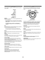
The Cool Down light illuminates during the cool down part of the
cycle. Laundry is cooling down for ease in handling.
2
The Cycle Complete light illuminates when a drying cycle is
finished. If the Extra Care feature has been selected, the Extra
Care feature indicator light will also be on.
The Cycle Complete light turns off 1 hour after the end of a drying
cycle (including the Extra Care cycle of 2 hours), when Off is
pressed, or when the door is opened.
732
Use this cycle to get Low heat for drying synthetic fabrics,
washable knit fabrics and no-iron finishes.
14 732
Use this cycle to get Extra-Low heat to gently dry items such as
lingerie, exercise wear or sheer curtains.
233 324
The Extra Care feature light illuminates when this option is
selected. This indicator stays on with the Cycle Complete light.
26 The Control Locked light illuminates when this option is enabled.
73278925
Other indicator lights on the control panel show Cycle,
Temperature and Cycle End Signal settings selected.
The time display will indicate the estimated or actual time
remaining in a cycle.
3-3
1234563789
3988 9 337
6789 8 9 3
3 3 78
46 !3
High
40
12"6
Medium
34
6#!6
Medium
36
Low
28
Extra Low
22
173746 632
3 696 9 632 9
When you are unable to remove a load of clothes from the dryer
as soon as it stops, wrinkles can form. The Extra Care feature
periodically tumbles, rearranges and fluffs the load to help reduce
wrinkling.
Press the Extra Care feature to get up to 120 minutes of heatfree, periodic tumbling at the end of a cycle.
Heavyweight mixed loads, towels,
jeans
Corduroys, work clothes, sheets
Stop at any time by pressing the Extra Care feature or
opening the dryer door.
Permanent press, synthetics
4$634
For the Casual Cycle, the Extra Care feature is preset to ?On.?
The other Automatic Cycles will retain the Extra Care feature
setting. (For example, if you select the Extra Care feature in
the Normal cycle, the Extra Care feature will be on the next
time you select the Normal cycle.)
Lingerie, blouses, washable
woolens 1
#!%4" 4$634
12345
If you do not select the Extra Care feature, the dryer stops
after the cool down period.
Exercise wear, sheer curtains, lace
5
*Estimated Time with Dryness Level (medium) setting.
11 Use Manual Cycles to select a specific amount of drying time and
a drying temperature. When a Manual Cycle is selected, the
ESTIMATED TIME REMAINING display shows the actual time
remaining in your cycle. You can change the actual time in the
cycle by pressing the Manual Dry Time (- or +) buttons.
632
Temperature settings are used with the Manual Cycles. Press
TEMP until the desired temperature setting illuminates.
Temperature settings cannot be used with the Automatic Cycles.
75 9 Use this cycle to complete drying if items are still damp after an
Automatic Cycle. Timed Dry is also useful for drying heavyweight
and bulky items, such as bedspreads and work clothes.
4282
Use this setting to help smooth out wrinkles from such items as
clothes packed in a suitcase or items wrinkled from being left in
the dryer too long.
17 9!
Use the Air Only setting for items that require drying without heat
such as rubber, plastic and heat-sensitive fabrics. This chart
shows examples of items that can be dried using Air Only.
6 79 Use this cycle for drying small loads or loads that need a short
drying time.
6269
3988 9 337
7 9 3
3 & 783 78
3$4 "
High
40
32!!%
Medium
20
"6%$ "
High
27
Heavyweight, bulky items,
bedspreads, work clothes
39&9 3 78
Foam rubber - pillows, padded bras,
stuffed toys
20 - 30
Plastic - Shower curtains, tablecloths
20 - 30
Rubber-backed rugs
40 - 50
Olefin, polypropylene, sheer nylon
10 - 20
*Reset time to complete drying, if needed.
Helps to smooth out
wrinkles
" 92 7917 9!
Check that coverings are securely stitched.
Small loads
Shake and fluff pillows by hand periodically during the cycle.
Dry item completely. Foam rubber pillows are slow to dry.
12345
Automatic Cycles are not available when using the Air
Only setting.
3-4
1234567896
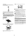
123457 Do not allow items to hang over the edge of the rack.
8 4
The Cycle End Signal produces an audible sound when the
drying cycle is finished. Promptly removing clothes at the end of
the cycle reduces wrinkling.
Press and release the (ADJUSTABLE) CYCLE END SIGNAL to
adjust the sound level or turn off the signal. Your dryer may vary
from the model shown and may not have the same feature as
shown here.
12345 When the Extra Care feature is selected and the Cycle
End Signal is on, an audible sound will emit every 5 minutes until
the clothes are removed, or the Extra Care feature is finished.
2 8 3
Close the door.
Select a Manual cycle, and choose a temperature or Air Only
(see following chart). Items containing foam, rubber or plastic
must be dried on a clothesline or by using the Air Only
temperature setting.
You must select a time by pressing the MANUAL DRY TIME
(- or +) buttons. Reset time as needed to complete drying.
Refer to the following table.
Press (and hold) HOLD TO START button (about 1 second).
12345 You must remove rack for normal tumbling. Do not use
automatic cycles with the drying rack.
This chart shows examples of items that can be rack dried and
the suggested cycle, temperature setting and drying time. Actual
drying time will depend on the amount of moisture items hold.
7
The drying rack is useful for drying items you would not
necessarily want to tumble dry or that you would normally line dry
(for example, sweaters).
36789 7
$66%7 & 9
7 7
Block to shape and lay flat on
the rack
Do not remove the lint screen.
Open dryer door.
8'' 7 69767"%%6&9
Cotton or polyester fiber filled
8'' 7 69767"%%6&9
Foam rubber filled
9767(979 6 9
1234567839
9
Place drying rack inside dryer drum, positioning the back wire
on the ledge of the inner dryer back panel. Push down on
front edge of drying rack to secure over the lint screen.
12 5 95353567839
2 5 953379
3 !"
3! #
Timed
Dry
Low
60
Timed
Dry
Low
60
Timed
Dry
Air Only
(no
heat)
90
Timed
Dry
Air Only
(no
heat)
90
*(Minutes) Reset time to complete drying, if needed.
9
Put the wet items on top of the rack. Leave space between
the items so air can reach all the surfaces.
3-5
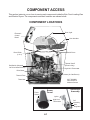
COMPONENT ACCESS
This section instructs you on how to service each component inside the Epic Front-Loading Gas
and Electric Dryers. The components and their locations are shown below.
COMPONENT LOCATIONS
Drum Light
Electronic
Control
Board
User Interface
Belt & Drum
Drum Roller
(1 of 4)
Thermal Cutoff
(Electric Only)
Belt Switch (Mounted
On Drive Motor Bracket)
High-Limit Thermostat
Drive Motor
Heater (Or Gas Burner)
Thermal Fuse
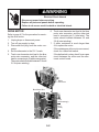
NOT SHOWN:
Door Switch &
Moisture Sensor
Thermistor
Flame
Sensor
Gas Burner
Assembly
Burner
Funnel
Ignitor
High-Limit
Thermostat
4-1
Coil
Assembly
Gas
Regulator
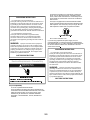
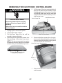
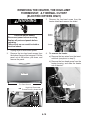
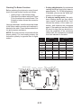
REMOVING THE ELECTRONIC CONTROL BOARD
5.
WARNING
Lift the rear of the top cover and slide it
back so the tabs clear the catches on the
bracket, and remove the cover from the
unit. NOTE: Make sure that the tabs slide
under the bracket catches when you reinstall the top cover.
Cover Flange Tab
Under Bracket Catch
Electrical Shock Hazard
Disconnect power before servicing.
Replace all parts and panels before
operating.
Failure to do so can result in death or
electrical shock.
1.
2.
3.
4.
Unplug dryer or disconnect power.
Turn off gas supply to dryer.
Pull the dryer away from the wall far
enough to access the back.
Remove the three hex-head screws from
the rear flange of the dryer’s top cover.
NOTE: The top cover screws have nylon
flat washers on them. Be sure to use these
screws when you reinstall the top cover.
Slide Top Cover Back
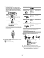
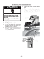
6.
Remove the three screws from the electronic control board bracket and pull the
bracket away from the side of the dryer so
you can access the connectors.
Electronic Control Board Bracket
Top Cover Rear Flange Screws
W/Nylon Flat Washers
Screws
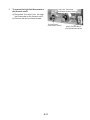
7.
4-2
Disconnect the 3-wire connector from the
main harness.
8.
Remove the following connectors and
wires from the electronic control board:
5-wire connector at P1.
Red and black wires at relay K1.
7-wire connector at P2.
Ribbon cables at P3 and P4.
P1
Relay K1
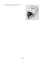
10. Squeeze the two board supports and remove the electronic control board from the
bracket.
P2
Squeeze Ends Of Supports To Remove Board
Electronic Control
Board
1/4 inch Screw
9.
Ribbon Cables 3-Wire
P3 & P4
Connector
Remove the 1/4 inch hex-head screw from
the electronic control board.
4-3
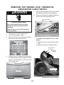
REMOVING THE CONSOLE & THE
TOUCHPAD SUBASSEMBLY
6.
WARNING
Console Bracket Screws
Electrical Shock Hazard
Disconnect power before servicing.
Replace all parts and panels before
operating.
Failure to do so can result in death or
electrical shock.
1.
2.
3.
4.
5.
Remove the two screws from the console
bracket.
Unplug dryer or disconnect power.
Turn off gas supply to dryer.
Pull the dryer away from the wall and
remove the top cover (see steps 4 and 5
on page 4-2 for the procedure).
Remove the three screws from the electronic control board bracket, and tip the
bracket assembly inside the dryer (see
step 6 on page 4-2 for the procedure).
Disconnect the ends of the two ribbon
cables from the electronic control board
connectors P3 and P4.
7.
Open the door and pull out on the bottom
of the console to release the locking tabs
from the door panel.
8.
Lift the console straight up until the brackets are free of the left and right side panel
flanges and remove the console.
Viewed From Back Of Console
Lift Console Bracket From
Flange On Both Sides
Side Panel Flange
P4
P3
Electronic
Control
Board
Press In On Clips To
Release Cables
4-4
9.
Place the console assembly on a padded
work surface with the bracket side facing
up, as shown in step 10.
10. Remove the four hex-head screws from
the console bracket and remove the
bracket.
11. Remove the selector knob.
12. Remove the touchpad subassembly from
the console by unsnapping the six catches.
Use your thumb or a screwdriver.
Console Bracket Screws
Console Bracket
Touchpad Subassembly
Console
Subpanel Catch
(1 of 6)
4-5
REMOVING THE DOOR SWITCH
5.
WARNING
6.
Electrical Shock Hazard
Disconnect power before servicing.
Replace all parts and panels before
operating.
Failure to do so can result in death or
electrical shock.
1.
2.
3.
4.
Push the wire holder out of the chassis
hole.
Press a screwdriver blade against the
locking arms on each side of the door
switch, (from behind the cutout), and push
the switch and wiring harness out.
Screwdriver
Removal
Unplug dryer or disconnect power.
Turn off gas supply to dryer.
Pull the dryer away from the wall and
remove the top cover (see steps 4 and 5
on page 4-2 for the procedure).
Remove the console (see page 4-4 for the
procedure). Tip the console back and lay
it on a padded surface.
Wire Holder
Door Switch
Brown Wire
(N.C.)
White Wire
(COM)
4-6
Blue Wire
(N.O.)
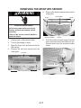
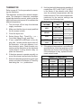
REMOVING THE THERMAL FUSE, THERMISTOR,
DRIVE MOTOR, & BELT SWITCH
5.
WARNING
6.
Remove the hex-head screw from the lint
duct bracket and remove the bracket.
Remove the three hex-head screws from
the lint duct and remove the duct.
Lint Duct Screws
Electrical Shock Hazard
Disconnect power before servicing.
Replace all parts and panels before
operating.
Failure to do so can result in death or
electrical shock.
1.
2.
3.
Unplug dryer or disconnect power.
Turn off gas supply to dryer.
Open the dryer door and remove the lint
filter screen, then close the door.
7.
Lint Filter Screen
To remove the thermal fuse or thermistor:
a) Remove the two wires from the terminals.
b) Remove the two hex-head screws.
Thermal Fuse
(2 Screws)
Thermistor
(2 Screws)
4.
Remove the two hex-head screws from
the bottom flange of the toe panel. Pull the
panel out at the bottom, pull down, and
remove the panel.
Blower Cover
Toe Panel
Continued on the next page.
Toe Panel Screws
4-7
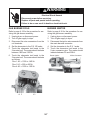
8.
To remove the drive motor:
a) Remove the wires from the thermal
fuse and thermistor terminals (see the
photo in step 7 on page 4-7).
b) Reach around behind the drive motor
and push the idler wheel arm to the left,
then remove the tension, and remove
the belt from the idler pulley.
7/16 inch OpenEnd Wrench
Remove Belt
From Idler Pulley
Blower Wheel
Push To Left
Remove
1/2 inch Drive
Refer to the photos at the top of the right
column for the next two steps.
c) Reach around to the back of the drive
motor and attach a 7/16 inch open-end
wrench over the flat of the motor shaft,
and a ratchet with a 1/2 inch drive on the
blower wheel hub.
d) Turn the blower wheel clockwise (shown
by the “REMOVE” arrow that is embossed on the front of the wheel ) and
remove the wheel from the motor shaft.
Tighten
e) Remove the three hex-head screws
from the blower housing and remove it.
Blower Housing
Housing Screw (1 of 3)
4-8
g) Lift the top locking tab of the motor
harness plug and pull the top pins away
from the motor connector, then release
the bottom tab, and remove the plug.
Top Locking Tab
9.
To remove the belt switch:
a) Remove the 3/8 inch hex shoulderwasher screw from the idler pulley assembly and remove the assembly.
Motor Harness Plug
3/8 inch Hex Shoulder
Washer Screw
Idler Pulley Assembly
b) Remove the two screws from the belt
switch and remove it from the motor.
h) Remove the two hex washer-head
mounting screws from the drive motor,
then lift the right side of the motor
slightly, pull the two tabs on the left side
out of the chassis slots, and remove the
drive motor.
Belt Switch Screws
c) Disconnect the blue wires from the belt
switch terminals.
Blue Wire
Blue Wire
Belt Switch
Hex Washer-Head Screws
4-9
REMOVING THE HEATER, THE HIGH-LIMIT
THERMOSTAT, & THERMAL CUTOFF
(ELECTRIC DRYERS ONLY)
3.
WARNING
Heater
Shield
Electrical Shock Hazard
Disconnect power before servicing.
Replace all parts and panels before
operating.
Failure to do so can result in death or
electrical shock.
1.
2.
Remove the hex-head screw from the
heater shield and remove the shield.
Screw
Unplug dryer or disconnect power.
Remove the two hex-head screws from
the bottom flange of the toe panel. Pull the
panel out at the bottom, pull down, and
remove the panel.
4.
To remove the heater:
a) Remove the two wires from the terminal block (see photo in step 5).
b) Remove the hex-head screw from the
heater housing, and slide the heater
out of the duct.
Toe Panel
Toe Panel Screws
Heater Housing
Screw
High-Limit Thermostat,
Thermal Cutoff, & Heater Area
4-10
5.
To remove the high-limit thermostat or
the thermal cutoff:
a) Disconnect the wires from the highlimit thermostat or the thermal cutoff.
b) Remove the two hex-head screws.
High-Limit Thermostat
(Red-White & Black Wires)
Thermal Cutoff
(Red & Black Wires)
4-11
Heater Terminal Block
(Red & Red-White Wires)
REMOVING THE BELT, DRUM, & ROLLERS
7.
WARNING
Electrical Shock Hazard
Disconnect power before servicing.
Replace all parts and panels before
operating.
Failure to do so can result in death or
electrical shock.
1.
2.
3.
4.
5.
6.
Disconnect the 3-wire moisture sensor connector from the main harness connector.
Moisture Sensor
Connector
Unplug dryer or disconnect power.
Turn off gas supply to dryer.
Pull the dryer away from the wall and
remove the top cover (see steps 4 and 5
on page 4-2 for the procedure).
Remove the console (see page 4-4 for the
procedure).
Remove the lint duct (see steps 3 through
6 on page 4-7 for the procedure).
Reach around behind the drive motor and
push the idler wheel arm to the left, then
remove the tension, and remove the belt
from the idler pulley.
8.
Disconnect the 3-wire door switch connector from the electronic control board
connector.
3-Wire
Door Switch
Connector
9.
Remove Belt
From Idler Pulley
Loosen the two top front panel screws.
Top Front Panel Screws
Push To Left
10. Remove the two bottom front panel screws.
Bottom Front Panel Screws
4-12
11. To remove the belt and drum:
a) Grasp the sides, lift, and pull the front
panel forward so that the top screws
are free of the keyhole slots. Lower the
panel so that the drum sits on the components inside the cabinet, and slide
the front panel and rollers away from
the drum.
c) Lift the drum and remove it from the
unit.
Keyhole Slot
REASSEMBLY NOTE: Use the following illustration as a guide when installing a new belt.
b) Slide the belt off the drum.
Drum
Belt
Idler
Pulley
Drive Motor Pulley
Continued on the next page.
4-13
DRUM INSTALLATION NOTE: Be sure to
position the drum with the clip toward the rear
when you reinstall it.
Front
NOTE: There are two rollers on the front panel
and two on the rear panel, as shown below.
Front Panel (inside)
Rear Panel (inside)
Position Clip
Towards Rear
Front Rollers
Rear Rollers
12. To remove a roller:
a) Pry the sides of the triangular ring out
of the groove in the roller support with
a small screwdriver.
Triangular Ring (Partially Removed)
Install Drum
b) Slide the roller off the roller support.
Roller Support
4-14
REMOVING THE DRUM LIGHT SOCKET
5.
WARNING
6.
Electrical Shock Hazard
Disconnect power before servicing.
Replace all parts and panels before
operating.
Failure to do so can result in death or
electrical shock.
1.
2.
3.
4.
Drum Light
Holder Screw
Bulb
Unplug dryer or disconnect power.
Turn off gas supply to dryer.
Open the dryer door.
Remove the screw from the drum light
lens and remove the lens.
7.
Drum Light Lens
Remove the bulb from the drum light
socket.
Remove the screw from the drum light
holder and pull it forward so you can
access the wires.
Disconnect the wire connectors from the
light socket terminals.
Lens Screw
Wire Connectors
Light Socket
Continued on the next page.
4-15
8.
Squeeze the locking arms and remove the
socket from the drum light holder.
Squeeze
Arms
4-16
REMOVING THE MOISTURE SENSOR
5.
WARNING
Remove the three inside screws from the
outlet grille.
Screw
Electrical Shock Hazard
Disconnect power before servicing.
Replace all parts and panels before
operating.
Failure to do so can result in death or
electrical shock.
1.
2.
3.
4.
Moisture Sensor
Unplug dryer or disconnect power.
Turn off gas supply to dryer.
Open the dryer door and remove the lint
filter screen.
Remove the two front screws from the
outlet grille.
6.
Outlet Grille
Screw
Screw
Pull the moisture sensor away from the
dryer and disconnect the black and yellow-red wires from the moisture sensor
strips.
Lint Filter
Black Wire
Yellow-Red Wire
Outlet Grille Screws
4-17
REMOVING THE BURNER ASSEMBLY,
FLAME SENSOR, AND HIGH-LIMIT THERMOSTAT
(GAS DRYERS ONLY)
WARNING
Burner Assembly
Electrical Shock Hazard
Disconnect power before servicing.
Replace all parts and panels before
operating.
Failure to do so can result in death or
electrical shock.
1.
2.
3.
4.
Unplug dryer or disconnect power.
Turn off gas supply to dryer.
Remove the two hex-head screws from
the bottom flange of the toe panel. Pull the
panel out at the bottom, pull down, and
remove the panel.
To remove the burner assembly:
a) Remove the two hex-head screws from
the burner support bracket, and pull the
bracket away from the burner assembly.
Screws
Toe Panel
Toe Panel Screws
4-18
Burner Support
b) Disconnect the following wires from the
burner assembly:
• Blue and white wires from the flame
sensor terminals.
• 2-wire connector from the ignitor.
• 2-wire and 3-wire connectors from
the coil assembly.
Flame Sensor
Wht & Blu Wires
e) Remove the two hex-head screws from
the burner mounting bracket, and pull
the burner assembly out of the unit.
Coil Assembly 2-Wire Connector
3-Wire Connector
Bracket Screws
Ignitor Connector
Burner Assembly
c) Disconnect the gas line from the burner
manifold at the right rear corner of the
dryer.
d) Loosen the burner manifold clamp at
the inside back of the dryer.
f) To remove the ignitor from the burner
assembly, loosen the 5/16 inch hexhead screw, and remove the ignitor
from the mounting bracket.
Ignitor
Screw
Bracket
Continued on the next page.
Manifold Clamp Screw
4-19
g) To remove the coils from the burner
assembly, remove the two screws from
the bracket, and lift the two coils off the
cores.
b) Remove the hex-head screw from the
flame sensor and remove the sensor
from the venturi.
Screw
Bracket Screws
Flame Sensor
6.
Coils
To remove the high-limit thermostat:
a) Remove the venturi (see step 5).
b) Disconnect the two wire connectors
from the high-limit thermostat.
c) Remove the two hex-head screws from
the high-limit thermostat and remove
the thermostat.
High-Limit Thermostat
Screw
5.
To remove the flame sensor:
a) Remove the two hex-head screws from
the venturi and pull it forward so you
can access the flame sensor.
Screw
Wires
High-Limit Thermostat
Flame Sensor
Venturi Screws
4-20
COMPONENT TESTING
Before testing any of the components, perform
the following checks:
• Control failure can be the result of corrosion on connectors. Therefore, disconnecting and reconnecting wires will be necessary throughout test procedures.
• All tests/checks should be made with a
VOM or DVM having a sensitivity of 20,000
ohms-per-volt DC, or greater.
• Check all connections before replacing components, looking for broken or loose wires,
failed terminals, or wires not pressed into
connectors far enough.
• Resistance checks must be made with
power cord unplugged from outlet, and with
wiring harness or connectors disconnected.
For any additional test beyond what is covered
in this Component Testing section, refer to the
Tech Sheet that is supplied with the product.
WARNING
Electrical Shock Hazard
Disconnect power before servicing.
Replace all parts and panels before operating.
Failure to do so can result in death or electrical shock.
HEATER
Refer to page 4-10 for the procedure for servicing the heater.
1. Unplug dryer or disconnect power.
2. Disconnect one of the wire connectors from
the heater terminal block.
3. Set the ohmmeter to the R X 1 scale.
4. Touch the ohmmeter test leads to the terminals on the heater terminal block. The
meter should indicate between 7 and 12 Ω.
Heater Terminal Block
5-1
WARNING
Electrical Shock Hazard
Disconnect power before servicing.
Replace all parts and panels before operating.
Failure to do so can result in death or electrical shock.
DRIVE MOTOR
6. Touch one ohmmeter test lead to the blue
motor wire connector, and the other test
lead to connector pin 3 (violet wire). The
meter should indicate between 2.4 and
3.8 Ω (start winding).
7. If either resistance is much larger than
4 Ω, replace the motor.
If the resistances at the motor are correct,
check for a failed belt switch.
If the belt switch is okay, check for an open
circuit between the motor and the electronic control board.
Refer to page 4-7 for the procedure for servicing the drive motor.
1. Unplug dryer or disconnect power.
2. Turn off gas supply to dryer.
3. Disconnect the plug from the motor connector.
4. Set the ohmmeter to the R X 1 scale.
5. Touch one ohmmeter test lead to the blue
motor wire connector, and the other test
lead to connector pin 5 (white-orange wire).
The meter should indicate between 2.4 and
3.6 Ω (main winding).
Motor
Connector
Blue Motor Wire
Pin 5
(white-orange)
Pin 3
(violet)
5-2
WARNING
Electrical Shock Hazard
Disconnect power before servicing.
Replace all parts and panels before operating.
Failure to do so can result in death or electrical shock.
THERMAL FUSE
Refer to page 4-7 for the procedure for servicing the thermal fuse.
Electric Dryers: The thermal fuse is wired in
series with the drive motor. If the thermal fuse
opens, 91°C (196°F), power to the motor is
turned off. A centrifugal switch on the motor
also opens the heater circuit.
Once the thermal fuse has opened, it will not
reset, and must be replaced. Check for a failed
thermistor, or a shorted heater element.
Gas Dryers: The thermal fuse is wired in
series with the gas valve. If the thermal fuse
opens, 91°C (196°F), power to the valve is
turned off. A centrifugal switch on the motor
also opens the heater circuit.
Once the thermal fuse has opened, it will not
reset, and must be replaced. Check for a failed
thermistor.
Thermal Fuse
91°C (196°F)
Blower
Housing
1.
2.
3.
4.
5.
5-3
Unplug dryer or disconnect power.
Turn off gas supply to dryer.
Disconnect the wires from the thermal fuse.
Set the ohmmeter to the R X 1 scale.
Touch the ohmmeter test leads to the thermal fuse terminals. The meter should indicate continuity (0 Ω). If the meter indicates
an open circuit (infinite), replace the thermal fuse.
THERMISTOR
8. Hold a glass bulb thermometer capable of
reading from 32°C to 82°C (90°F to 180°F)
in the center of the exhaust outlet. Measure the exhaust temperatures with the
heater on and off. The correct exhaust temperatures for the various settings are
shown in the following chart.
Refer to page 4-7 for the procedure for servicing the thermistor.
The thermistor monitors the exhaust temperature. The changes in thermistor resistance
signals the electronics control, which cycles the
high-limit thermostat on and off to maintain the
desired temperature.
1. Turn the dryer off but keep the electrical
supply connected.
2. Make sure that the dryer is empty and that
the lint screen is clean.
3. Close the dryer door.
4. Select Heavy Duty, Timed Dry, + or –,
Cycle End Signal (Loud), and Start.
5. If error codes E1 or E2 flash on the display after 1 minute and the dryer turns off,
the thermistor, or the wire harness, is either shorted or open. Check the wire connections at the thermistor or the electronic
control board. If wiring checks okay, replace the thermistor.
6. If the dryer seems to operate normally, remove the exhaust vent and start the dryer.
7. Select the desired temperature cycle to be
tested, and select 20 minutes of Timed Dry
heat using the + or – pushbuttons.
TEMPERATURE
SETTING
HIGH
MEDIUM
LOW
EXTRA
LOW
HEAT TURNS
OFF
HEAT TURNS
ON
68° C ±6°
(155° F ±10°)
6 - 8°C
60° C ±6°
(10 - 15°F)
(140° F ±10°) below the heat
52° C ±6°
turn off
(125° F ±10°) temperature
41° C ±3°
(105° F ±5°)
9. If the exhaust temperature is not within the
specified limits, check the resistance of the
thermistor, as shown in the following chart.
If the resistance is okay, replace the electronic control board.
THERMISTOR RESISTANCE
TEMP RESISTANCE TEMP RESISTANCE
°C (°F)
(K ohms )
(K ohms )
°C (°F)
10° (50°)
16° (60°)
21° (70°)
27° (80°)
32° (90°)
38°(100° )
5-4
19.9
15.3
11.9
9.2
7.4
5.7
43° (110°)
49° (120°)
54° (130°)
60° (140°)
66° (150° )
71° (160° )
4.7
3.7
3.1
2.5
2.1
1.7
WARNING
Electrical Shock Hazard
Disconnect power before servicing.
Replace all parts and panels before operating.
Failure to do so can result in death or electrical shock.
THERMAL CUTOFF
(ELECTRIC DRYERS ONLY)
Refer to page 4-10 for the procedure for servicing the thermal cutoff.
The thermal cutoff is a non-resettable device.
The cutoff temperature is 178°C (352°F).
If the dryer does not heat and there is 240 VAC
to the dryer, perform the following test.
Thermal Cutoff
High-Limit
Thermostat
1. Unplug dryer or disconnect power.
2. Disconnect the wires from the thermal cutoff.
3. Set the ohmmeter to the R X 1 scale.
4. Touch the ohmmeter test leads to the thermal cutoff terminals. The meter should indicate continuity (0 Ω). If the meter indicates an open circuit (infinite), replace both
the thermal cutoff and the high-limit thermostat. In addition, check for a failed
heater element, or a blocked, or improper
exhaust system.
Heater Terminals
5-5
WARNING
Electrical Shock Hazard
Disconnect power before servicing.
Replace all parts and panels before operating.
Failure to do so can result in death or electrical shock.
DOOR SWITCH
Resistance Tests
Refer to page 4-6 for the procedure for servicing the door switch.
1. Go into the Diagnostic Test mode on page 62. The door switch function is verified with
a beep each time the door is opened and
closed, and an alpha numeric code appears in the display (“0E”, “0g”, “1E”, or
“2E”).
2. If any of the conditions are not met, or if
one of the dryer model codes listed above
is displayed when the door is closed, check
that the wires between the door switch and
the electronic control board are properly
connected.
If the wiring is okay, perform the resistance
tests.
1.
2.
3.
4.
Unplug dryer or disconnect power.
Turn off gas supply to dryer.
Close the dryer door.
Disconnect the 3-wire connector from the
door switch to the electronic control board.
5. Set the ohmmeter to the R X 1 scale.
Refer to the illustration below for the following
tests.
6. Touch the black ohmmeter test lead to the
white wire pin in the connector and leave
it there for the remaining tests.
7. Touch the red ohmmeter test lead to the
brown wire pin in the connector. The meter
should indicate an open circuit (infinite).
8. Touch the red ohmmeter test lead to the
blue wire pin in the connector. The meter
should indicate a closed circuit (0 ohms).
9. Open the dryer door.
10. Touch the red ohmmeter test lead to the
blue wire pin in the connector. The meter
should indicate an open circuit (infinite).
11. Touch the red ohmmeter test lead to the
brown wire pin in the connector. The meter
should indicate a closed circuit (0 ohms).
12. If the resistance test is incorrect, replace
the wire and door switch assembly, (see
page 4-6 for the procedure), and retest.
Door Switch Connector
Door Switch
5-6
WARNING
Electrical Shock Hazard
Disconnect power before servicing.
Replace all parts and panels before operating.
Failure to do so can result in death or electrical shock.
GAS BURNER COILS
BURNER IGNITOR
Refer to page 4-18 for the procedure for servicing the gas burner assembly.
1. Unplug dryer or disconnect power.
2. Turn off gas supply to dryer.
3. Disconnect the wire connectors from the
coil terminals.
4. Set the ohmmeter to the R X 100 scale.
5. Touch the ohmmeter test leads to the
2-terminal coil. The meter should indicate
between 1000 and 1300 Ω.
6. Touch the ohmmeter test leads to the
3-terminal coil. The meter should indicate
as follows:
Pins 1 & 2 = 1300 to 1400 Ω
Pins 1 & 3 = 500 to 600 Ω
Pins 4 & 5 = 1200 to 1300 Ω
Refer to page 4-18 for the procedure for servicing the gas burner assembly.
1. Unplug dryer or disconnect power.
2. Turn off gas supply to dryer.
3. Disconnect the ignitor wire connector from
the main harness connector.
4. Set the ohmmeter to the R X 1 scale.
5. Touch the ohmmeter test leads to the
2-wire connector pins. The meter should
indicate between 50 and 250 Ω.
1 2 3
Burner Ignitor
4 5
5-7
2-Wire Connector
WARNING
Electrical Shock Hazard
Disconnect power before servicing.
Replace all parts and panels before operating.
Failure to do so can result in death or electrical shock.
FLAME SENSOR
HIGH-LIMIT THERMOSTAT
Refer to page 4-18 for the procedure for servicing the flame sensor.
1. Unplug dryer or disconnect power.
2. Turn off gas supply to dryer.
3. Disconnect the wire connectors from the
flame sensor terminals.
4. Set the ohmmeter to the R X 1 scale.
5. Touch the ohmmeter test leads to the flame
sensor terminals. The meter should indicate a closed circuit (0 Ω).
Refer to pages 4-10 or 4-18 for the procedure
for servicing the high-limit thermostat.
1. Unplug dryer or disconnect power.
2. Turn off gas supply to dryer.
3. Disconnect the wire connectors from the
high-limit thermostat terminals.
4. Set the ohmmeter to the R X 1 scale.
5. Touch the ohmmeter test leads to the highlimit thermostat terminals. The meter
should indicate a closed circuit (0 Ω).
Terminals
High-Limit
Thermostat
Flame Sensor
Terminals
5-8
DIAGNOSTICS AND TROUBLESHOOTING
DIAGNOSTICS
WARNING
IMPORTANT
Electrostatic Discharge (ESD)
Sensitive Electronics
ESD problems are present everywhere. ESD
may damage or weaken the electronic control board. The new control assembly may
appear to work well after repair is finished,
but failure may occur at a later date due to
ESD stress.
• Use an anti-static wrist strap. Connect
wrist strap to green ground connection
point or unpainted metal in the appliance.
-ORTouch your finger repeatedly to a green
ground connection point or unpainted metal
in the appliance.
• Before removing the part from its package, touch the anti-static bag to a green
ground connection point or unpainted metal
in the appliance.
• Avoid touching electronic parts or terminal
contacts; handle electronic control board
by edges only.
• When repackaging failed electronic control board in anti-static bag, observe above
instructions.
Electrical Shock Hazard
Disconnect power before servicing.
Replace all parts and panels before
operating.
Failure to do so can result in death or
electrical shock.
DIAGNOSTIC GUIDE
Before servicing, check the following:
• Make sure there is power at the wall outlet.
• Has a household fuse blown or circuit breaker
tripped? Time delay fuse?
• Is dryer vent properly installed and clear of
lint or obstructions?
• All tests/checks should be made with a VOM
or DVM having a sensitivity of 20,000 ohms
per volt DC or greater.
• Check all connections before replacing components. Look for broken or loose wires,
failed terminals, or wires not pressed into
connectors far enough.
• The most common cause for control failure is
corrosion on connectors. Therefore, disconnecting and reconnecting wires will be necessary throughout test procedures.
• Connectors: Look at top of connector. Check
for broken or loose wires. Check for wires not
pressed into connector far enough to engage metal barbs.
• Resistance checks must be made with power
cord unplugged from outlet.
6-1
DISPLAY FAULT/ERROR CODES
DISPLAY DESCRIPTION
EXPLANATION AND RECOMMENDED PROCEDURE
“PF” flashes to indicate that a power failure occurred while
PF
Power failure the dryer was running. Press HOLD TO START to continue
E1
Thermistor
open
“E1” flashes if the thermistor is open. See TEST #3a.
E2
Thermistor
shorted
“E2” flashes if the thermistor has shorted. See TEST #3a.
E3
User
interface or
software
mismatch
“E3” flashes when there is a keyswitch or software
mismatch. This error code will ONLY appear when in the
Diagnostic Test mode. See TEST #5.
the cycle, or press OFF/Pause to clear the display.
DIAGNOSTIC TESTS
If the entry into the diagnostic mode was unsuccessful, take the following actions for specific indications:
Indication 1: None of the indicators or display
turns on.
Action: Select any Manual Cycle. If the indicators turn on, then try to change the dryer
time by pressing the + and – buttons. If either
button fails to change the time, something is
faulty with one of those buttons, and it is not
possible to enter the diagnostic mode. Remove
the console electronics and housing. If no indicators come on after pressing the Manual
Cycle buttons, go to TEST #1 (Supply Connections) on page 6-4.
These tests allow factory or service personnel
to test and verify all inputs to the electronic
control board. It would be a good idea to perform a quick, overall checkup of the dryer with
these tests before going to any specific troubleshooting tests.
Activating The Diagnostic Test Mode
1. Be sure the dryer is in the Standby Mode
(plugged in and all indicators off).
2. Press the following button sequence within
5 seconds of power up:
+ (more time)
– (less time)
+ (more time)
– (less time)
3.
Indication 2: E1 or E2 flashes on the display.
Action: Proceed to TEST #3a (Thermistor
Test) on page 6-8.
If this test mode has been entered successfully, all indicators on the console are
illuminated, with “88” showing in the “Estimated Time Remaining” (2-digit) display.
Indication 3: E3 flashes on the display.
Action: Check to make sure that the correct
electronic control board, console electronics,
and housing are installed.
6-2
Diagnostic: Console switches and indicators.
Pressing each button, or turning the cycle selector to each cycle, should cause a beep tone
and control one or more LEDs. Pressing the
Hold To Start button will also control the motor
and heater, while the 2-digit display will indicate a software project identification number.
Diagnostic: Moisture Sensor
Locate the two metal strips on the face of the
lint screen housing. Bridge these strips with a
wet cloth or a finger. If a beep is heard, and a
software revision number is displayed on the
console, the sensor is okay. If not, or if a beep
tone is heard before bridging the moisture
strips, go to TEST #4, (Moisture Sensor Test),
step 2, on page 6-10.
Diagnostic: Door Switch
Opening the door should cause a beep tone
and a number and letter to be indicated in the
2-digit display. Closing the door firmly should
cause a beep tone and the display to go blank,
or indicate “88”.
Controls Status LEDs and turns on dryer
Start button
controls these
LEDs
Control On button controls this LED
Cycle selector controls
LED where pointing
This button controls
the left digit
6-3
This button controls
the right digit
Each button controls
all LEDs above button
Turns off all LEDs and
exits diagnostic mode
TROUBLESHOOTING
TROUBLESHOOTING GUIDE
PROBLEM
POSSIBLE CAUSE / TEST
NOTE: Possible Cause/Tests MUST be performed
in the sequence shown for each problem.
WILL NOT POWER UP.
1. Supply connection. See TEST #1.
(No response when Control 2. Check harness connections.
On button is pressed.)
3. Console electronics and housing. See TEST #5.
WILL NOT START CYCLE
WHEN START BUTTON IS
PRESSED.
WILL NOT SHUT OFF
WHEN EXPECTED.
1. If number display flashes, check to be sure the
door is completely shut, and press and hold
down HOLD TO START for about 1 second.
2. See TEST #2.
3. See TEST #6.
1. Check OFF/Pause button. See TEST #5.
2. Console electronics and housing. See TEST #5.
3. Moisture Sensor. See TEST #4.
CONTROL WILL NOT
ACCEPT SELECTIONS.
Console electronics and housing. See TEST #5.
WILL NOT HEAT.
1. Heater. See TEST #3.
2. Check harness connections.
3. Check installation.
HEATS IN AIR CYCLE.
Thermistor. See TEST #3a.
SHUTS OFF BEFORE
CLOTHES ARE DRY.
Moisture Sensor. See TEST #4.
TROUBLESHOOTING TESTS
3.
NOTE: These checks are done with the dryer
unplugged or disconnected from power.
TEST #1: SUPPLY CONNECTIONS
This test assumes that proper voltage is
present at the outlet.
1. Unplug dryer or disconnect power.
2. Remove the cover plate from the top right
corner of the back of the dryer.
Gas Dryers Only:
a) Check that the power cord is firmly connected to the dryer’s wire harness.
b) Access the electronic control board
without disconnecting any wiring to the
control board.
Wire Harness
Remove Screw
Power Cord
Cover Plate
Power Cord-To-Wire Harness
Connection For Gas Dryer
6-4
• If there is no continuity, replace the
power cord and test the dryer.
• If there is continuity, go to step b.
b) In a similar way, check which terminal
of the plug is connected to the left-most
contact on the terminal block, and make
a note of it. This will be L1 (black wire)
in the wiring diagram.
• When this is found, go to step c.
• If neither of the plug terminals have
continuity with the left-most contact
of the terminal block, replace the
power cord, and test the dryer.
c) Access the electronic control board
without disconnecting any wiring to the
control board.
d) With an ohmmeter, check for continuity
between the L1 terminal of the plug and
P1-5 (black wire) on the electronic control board.
• If there is continuity, go to step e.
• If there is no continuity, check that
wires to the terminal block are mechanically secure. If so, replace the
main wire harness, and test the dryer.
e) Check for continuity between the neutral (N) terminal of the plug and P1-2
(white wire) at the control board.
• If there is continuity, go to step f.
• If there is no continuity and the mechanical connections of the wire are
secure, replace the main wire harness.
f) If the dryer still does not operate, replace the electronic control board.
c) With an ohmmeter, check for continuity
between the neutral (N) terminal of the
plug and P1-2 (white wire) on the electronic control board.
• If there is continuity, go to step d.
• If there is no continuity, disconnect
the white wire of the harness from
the power cord at the location shown
in step 3b. Test the continuity of the
power cord neutral wire as shown
below. If an open circuit is found, replace the power cord.
• Otherwise, proceed to step d.
Power Cord Plug
N
L1
COM
Gas Dryers
L1
N
G
G
Power Cord Terminals
d) In a similar way, check the continuity between the L1 terminal of the plug and
P1-5 (black wire) on the control board.
• If there is continuity, replace the control board.
• If there is no continuity, check the
continuity of the power cord for the
L1 wire.
• If an open circuit is found, replace
the power cord.
• Otherwise, proceed to step e.
e) Replace the main wire harness.
4.
Electric Dryers Only:
a) With an ohmmeter, check for continuity
between the neutral (N) terminal of the
plug and the center contact on the terminal block.
Electric Dryers
L1 Terminal Block
Power Cord Plug
N
COM
6-5
7.
TEST #2: MOTOR CIRCUIT TEST
This test will check the wiring to the motor and
the motor itself. The following items are part of
this system:
• Harness/connection
• Thermal fuse (electric dryers only)
• Belt/belt switch
• Drive motor
• Door switch
• Electronic control board
1.
2.
Unplug dryer or disconnect power.
Access the electronic control board and
measure the resistance across P1-3 and
P1-4.
• If resistance across P1-3 and P1-4 is in
the range of 1 to 6 ohms, replace the
electronic control board.
• Otherwise, go to step 3.
3.
Check the wiring and components in the
path between these measurement points
(refer to the Wiring Diagrams in Section 7).
Electric Dryers Only: Check the thermal
fuse (see TEST #3b on page 6-9).
Check the belt switch and drive motor.
4.
5.
Check for the resistance values of the
motor’s Main and Start winding coils, as
shown in the following table. NOTE: Main
and Start winding coils must be checked at
the motor.
W i n di n g
R e s i s t a nc e
T es t P oints
MA IN
2.4 - 3.6
ohms
S T AR T
2.4 - 3.8
ohms
B lue wire in
back &
B lue wire in
back & violet
Main Winding: Blue Wire In Back And White/Orange Wire
Start Winding: Blue Wire In Back And Violet Wire
• If the resistance at the motor is correct,
there is an open circuit between the
motor and electronic control board.
Check for a failed belt switch.
8.
Belt Switch Pulley
Check the belt switch by measuring resistance between the two blue wires, while
pushing up on the belt switch pulley.
Drum Belt
Blue Wires
6.
Remove the white connector from the
drive motor switch.
Drive Motor Switch
Belt Switch Pulley
White Connector
Belt Switch
• If the resistance reading goes from infinity to a few ohms as pulley arm closes
the switch, belt switch is okay. If not,
replace the belt switch.
6-6
• If belt switch is okay and there is still an
open circuit, check and repair the wiring harness.
• If the Start winding is in question and
the resistance is much greater than
4 ohms, replace the motor.
3.
9.
Door switch problems can be found using
the Diagnostic Tests on page 6-2; however, if this was not done, the following
(step 10) can be done without applying
power to the dryer.
10. Connect the ohmmeter test leads to the
electronic control board at P1-2, (neutral,
white wire), and P1-3 (door, blue wire).
With the door closed, the ohmmeter should
indicate a closed circuit (0 to 2 Ω). If not,
replace the door switch assembly.
Gas Dryers Only:
a) Perform TEST #3b (Thermal Fuse Test).
If the thermal fuse is okay, proceed to
step b.
b) Connect the ohmmeter test leads to the
red wire and the blue wire of the highlimit thermostat.
• If there is an open circuit, replace the
high-limit thermostat.
• Otherwise, proceed to step c.
c) Perform TEST #3c (Gas Valve Test). If
this is okay, replace the electronic control board.
High Limit Thermostat
Flame Sensor
TEST #3: HEATER TEST
This test is performed when either of the following situations occur:
• Dryer does not heat
• Heat will not shut off
This test checks the components making up
the heating circuit. The following items are part
of this system:
•
•
•
•
•
•
•
•
•
•
•
•
Thermistor
Harness/connection
Heater relay
Thermal fuse (gas dryer only)
Thermal cutoff (electric dryer only)
High-limit thermostat
Gas burner assembly (gas dryer only)
Heat element assembly (electric dryer
only)
Centrifugal switch
Thermistor
Electronic control board
Console electronics & housing
Gas supply (gas dryer only)
Thermal Fuse
Continued on the next page.
Dryer does not heat:
1. Unplug dryer or disconnect power.
2. Remove the toe panel to access the thermal components.
6-7
4.
Heat will not shut off:
1. Unplug dryer or disconnect power.
2. Use an ohmmeter, and touch the test
leads to electronic control board points
P2-5 (red/white wire) and P2-6 (black wire).
• If 6 to 7 kΩ are measured, replace the
electronic control board.
• If the resistance is much greater than
7 kΩ, replace the thermistor.
Electric Dryers Only:
a) Connect the ohmmeter test probes to
the red wires at the thermal cutoff and
the heater.
• If the resistance is approximately
10 Ω, proceed to step c.
• If an open circuit is detected, go to
step b.
b) Visually check the wire connections to
the thermal cutoff, the high-limit thermostat, and the heater. If okay, check for
continuity (0 Ω), across each of the components. Replace the one that is electrically open.
TEST #3a: THERMISTOR TEST
The electronic control board monitors the exhaust temperature using the thermistor, and
cycles the heater relay on and off to maintain
the desired temperature. Begin with an empty
dryer and a clean lint screen.
1. Plug in dryer or reconnect power.
2. Set the dryer for the following configuration:
• Door firmly closed.
• Press CONTROL ON.
• Press CYCLE END SIGNAL (Loud).
• Press HOLD TO START.
Heater Element
Thermal Cut-Off
High Limit Thermostat
3.
Thermal Fuse
Thermistor
c) If no open circuit is detected, measure
the resistance between P2-5 (red/white
wire) and P2-6 (black wire) at the electronic control board.
• If 6 to 7 kΩ are measured, replace
the electronic control board.
• If the resistance is less than 1 kΩ,
replace the thermistor.
6-8
If after 60 seconds, E1 or E2 flashes in the
display and the dryer shuts off, the thermistor or wire harness is either shorted or
open.
• Unplug dryer or disconnect power.
• Check the wire connections at the electronic control board and thermistor.
• If the wire connections are good, remove the two wires from the thermistor,
and replace the thermistor.
• Plug in dryer or reconnect power.
4.
If E1 or E2 does not flash in the display, the
connections to the thermistor are good.
Therefore, check the thermistor’s resistance value at any or all of the temperature
levels in question, using the Timed Dry
Cycle, and the following process:
Hold a glass bulb thermometer capable of
reading from 32⋅ to 82⋅C (90⋅ to 180⋅F) in
the center of the exhaust outlet. The following table shows the correct exhaust
temperatures.
TEMP.
SETTING TEMPERATURE
5.
TEST #3b: THERMAL FUSE TEST
1. Unplug dryer or disconnect power.
2. Access the thermal fuse by first removing
the toe panel.
• Gas Dryers Only: The thermal fuse is
wired in series with the dryer gas valve.
If the thermal fuse is open, replace it.
• Electric Dryers Only: The thermal fuse
is wired in series with the dryer drive
motor. If the thermal fuse is open, replace it.
TEST #3c: GAS VALVE TEST
(GAS DRYERS ONLY)
1. Unplug dryer or disconnect power.
2. Access the gas valve by first removing the
toe panel.
3. Use an ohmmeter to determine if a gas
valve coil has failed. Remove harness
plugs. Measure resistance across terminals. Readings should match those shown
in the chart below. If the readings are not
as listed, replace the gas valve coil.
IMPORTANT: Be sure all harness wires are
looped back through the strain relief after
checking or replacing coils.
Thermistor resistance
value at heater
shutoff (digital or
analog meter) kΩ
High
155° ± 10°F
(68° ± 6°C)
2.5
1.5
Medium
140° ± 10°F
(60° ± 6°C)
4.0
3.0
Low
125° ± 10°F
(52° ± 6°C)
5
4.3
Extra Low
105° ± 5°F
(41° ± 3°C)
6
5
If the exhaust temperature is not within
specified limits, use the following table,
and check the resistance of the thermistor.
THERMISTOR RESISTANCE
TEMP.
°C (°F)
RES.
kΩ
TEMP.
°C (°F)
RES.
kΩ
10° (50°)
19.9
27° (80°)
9.2
16° (60°)
15.3
32° (90°)
7.4
21° (70°)
11.9
38° (100°)
5.7
1
2
NOTE: All thermistor resistance measurements must be made while dryer is unplugged or disconnected from power.
The table shown above gives the resistance values that should be observed for
the various temperature settings. If needed,
use table at the top of the right column to
find the temperatures and their associated
resistance values.
• If the thermistor resistance checks
within normal limits, replace the electronic control board.
6-9
3
4 5
Terminals Resistance
1 to 2
1365 Ω ±25
560 Ω ±25
1 to 3
1220 Ω ±50
4 to 5
TEST #3c: THERMAL CUTOFF TEST
(ELECTRIC DRYERS ONLY)
If the dryer does not produce heat, check the
status of the thermal cutoff.
1. Unplug dryer or disconnect power.
2. Access the thermal cutoff by first removing the toe panel.
3. Use an ohmmeter and check the continuity across the thermal cutoff.
• If the ohmmeter indicates an open circuit, replace the failed thermal cutoff and
high-limit thermostat. In addition, check
for failed heat element, or blocked or
improper exhaust system.
TEST #4: MOISTURE SENSOR TEST
NOTE: This test is performed when an automatic cycle stops too soon, or runs much longer
than expected. The test is started with the dryer
completely assembled. The dryer will shut
down automatically after 2-1/2 hours.
The following items are part of the moisture
sensor system:
• Harness/connection
• Metal sensor strips
• Electronic control board
1.
2.
3.
Enter the Diagnostic Test mode.
Open the dryer door. If a beep tone is
heard, and a software revision number is
displayed on the console as soon as the
door is opened, a short circuit exists in the
moisture sensor system.
• If this does not occur, proceed to step 3.
• Otherwise, go to step 4
NOTE: Overdrying may be caused by a
short circuit in the sensor system.
Bridge the two metal sensor strips on the
face of the lint screen housing with a wet
cloth or your finger.
• If a beep is heard and a software revision number is displayed on the console, the sensor has passed the test.
Proceed to step 4.
• If the test is not successful, unplug the
dryer or disconnect power.
• Access the moisture sensor and disconnect the sensor wires from the harness
(see the illustration below). Proceed to
step 8.
Drum
FRONT
Harness
Connection
Blower Housing
4.
5.
6.
7.
6-10
Unplug dryer or disconnect power.
Access the electronic control board and
remove the P2 connector from the board.
Use an ohmmeter and touch the test leads
to connector terminals 1 (yellow/red wire)
and 2 (black wire).
• If the meter does not indicate an open
circuit (infinite), go to step 6.
• Otherwise, measure the resistance at
pins 1 and 2 of connector P2 on the
electronic control board. If a resistance
less than 1 MΩ is measured, inspect
the control board for any debris bridging the pins. If no debris is present, replace the board.
Access the moisture sensor by removing
the toe panel. Disconnect the moisture
sensor from the wire harness.
Measure the resistance across the outermost contacts of the cable that includes
the two red discs (MOVs).
• If a small resistance is measured, replace the wire harness and moisture
sensor.
• Otherwise, go to step 8.
8.
Measure the resistance across the pins of
the mating connector. If a small resistance
is measured, replace this harness.
9. Measure the resistance across each of
the outermost contacts and the center pin
(ground).
• If a resistance less than infinity is measured, replace the wire harness and
moisture sensor.
10. If moisture sensor diagnostic test passes,
check the thermistor (perform Test #3a,
page 6-8).
• If the problem persists after replacing
the moisture sensor and thermistor, replace the electronic control board.
TEST #5: BUTTON & LED TEST
Activate the Diagnostic Test mode, and check
for the following situations:
• None of the LEDs light up.
• A particular group of LEDs does not light
up.
• A single LED does not light up.
• No beep sound is heard.
• No dryer function is activated when a
particular button is pressed.
• E3 error code is displayed.
None of the LEDs light up:
1. See “Diagnostic Guide” on page 6-1 before servicing.
2. Visually check that connectors P3 and P4
are inserted all the way into the electronic
control board. If these connections are
good, perform the checks described in
“Checking The Button Functions,” and
“Checking The Rotary Cycle Selector.”
• If this visual test passes, replace the
electronic control board.
• Otherwise, replace the console electronics and housing.
A particular group of LEDs does not light
up:
A group or combination of LEDs share a common electronic connection. If this connection
is open, all of the LEDs in the group will be
disabled. Replace the console electronics and
housing.
A single LED does not light up:
Press the button or manipulate the dial associated with the LED several times. If the LED
does not light up, the LED has failed. Replace
the console electronics and housing.
No beep sound is heard:
If the associated LEDs do light up, it is possible that the beeper circuit has failed. Check
functions of buttons before replacing the electronic control board.
No dryer function is activated when a
particular button is pressed:
If the associated LEDs do light up, it is possible that the electronic control board has failed.
Check functions of buttons before replacing the
electronic control board.
E3 error code is displayed:
If the E3 error code is displayed, there is a user
interface or software mismatch. It is also possible that a component on the console electronics or the electronic control board has
failed. Check functions of buttons before replacing the electronic control board. See
“Checking The Button Functions” on page
6-12.
6-11
Checking The Button Functions
Before replacing the electronic control board,
check for proper button function as follows:
• Unplug dryer or disconnect power.
• Disconnect the ribbon cables at P3 and
P4 on the electronic control board. The
illustration below shows the connector
locations.
Using an ohmmeter, touch the meter test leads
to the ribbon cable connector pin locations indicated in the table. Press the associated button and measure resistance.
NOTE: The meter must be connected with the
proper polarity. For most analog meters, the
connection polarity is opposite that of digital
meters.
• If using a digital meter, the resistance
reading should go from infinity down to
approximately 1 to 3.5 MΩ (megohms).
If available, you can use the “diode test”
function on the digital meter.
• If using an analog meter, the resistance reading should go from infinity
(open circuit) to less than 40 kΩ. If not,
reverse the polarity of the meter connection, and measure the resistance
again. If the reading is less than 40 kΩ,
the circuit is okay, and you should continue the remainder of the resistance
checks with the connections reversed
from that indicated in the table.
Button
TEMP
P3-12
P3-8
P3-12
P3-8
P3-13
P3-8
P3-13
P3-8
DRYNESS
LEVEL
P3-14
P3-7
P3-14
P3-7
+
P3-13
P3-7
P3-13
P3-7
–
P3-12
P3-7
P3-12
P3-7
CYCLE END
SIGNAL
P3-12
P4-2
P3-12
P4-2
HOLD TO
START
P3-14
P4-2
P3-14
P4-2
OFF/Pause
P3-13
P4-2
P3-13
P4-2
CONTROL ON
P3-12
P3-9
P3-12
P3-9
Black
Lt. Blue
Heater Relay
Red/White
N.O.
Open
Black
Yellow/Red
COM
6-12
Date CodeYDDD
Motor Relay
Analog Meter
– Lead
+ Lead
EXTRA CARE
P/N XXXXXXX Rev X
White Blue Light Blue
Black
Green/Yellow
Digital Meter
+ Lead
– Lead
Checking The Rotary Cycle Selector
Using the following table, check the resistance
at each cycle setting.
• When using a digital meter, touch the
“+” ohmmeter test lead to P1-14, and
leave it there during the tests. Touch the
other test lead to the test points indicated in the chart.
• When using an analog meter, touch the
“–” ohmmeter test lead to P1-14, and
leave it there during the tests. Touch the
other test lead to the test points indicated in the chart.
TEST #6: DOOR SWITCH TEST
Go into the Diagnostic Test mode on page 6-2.
The door switch function is verified with a beep
each time the door is opened and closed, and
an alpha numeric code appears in the display
(“0E”, “0g”, “1E”, or “2E”).
• If any of the conditions are not met, or if
one of the dryer model codes listed
above is displayed when the door is
closed, check that the wires between
the door switch and the electronic control board are properly connected.
• If the connections are okay, replace the
door switch assembly and its wiring, and
retest.
• If the door switch assembly and wiring
have been replaced and dryer still does
not start, replace the electronic control
board.
Digital Meter + Lead On P1-14
Cycle
Selection
P1-11
P1-10
Heavy Duty
•
Analog Meter – Lead On P1-14
P1-9
P1-8
P1-11
P1-10
P1-9
P1-8
•
•
•
•
•
•
•
Timed Dry
3.5 MΩ
•
3.5 MΩ
•
30 - 40 kΩ
•
10 - 20 kΩ
•
Touch Up
•
•
3.5 MΩ
•
•
•
10 - 20 kΩ
•
Rapid Dry
•
•
3.5 MΩ
1.59 MΩ
•
•
10 - 20 kΩ 10 - 20 kΩ
Super
Delicate
•
1.58 MΩ
•
290 kΩ
•
10 - 20 kΩ
•
10 - 20 kΩ
Delicate
3.5 MΩ
290 kΩ
•
290 kΩ 10 - 20 kΩ 10 - 20 kΩ
•
10 - 20 kΩ
Casual
3.5 MΩ
•
•
290 kΩ 30 - 40 kΩ
•
•
10 - 20 kΩ
Normal
•
•
•
290 kΩ
•
•
10 - 20 kΩ
• = Infinite
6-13
•
— NOTES —
6-14
WIRING DIAGRAMS
ELECTRIC DRYER
L1 LINE BK
W NEUTRAL
120 VOLTS
NEUTRAL
TERMINAL
LINKED TO
CABINET
BR
DL
BK
NC
COM
DRUM LAMP
BK
DOOR
P1-5
L1
NEUTRAL
P3
USER INTERFACE
MOTOR
(ACTIVE OVERLAY or
ALTERNATE TECHNOLOGY)
P1-1
BU
P1-3
5M
MOIST RTN
MODEL
HEATER
RELAY
N.O. HEATER +V
MODEL RTN
(0.250 TERMINAL)
COM
(0.250 TERMINAL)
TEMP.
HEATER RTN
TEMP RTN
N.C.
MAIN
2.4 -3.6
START
2.4 -3.8
4M
P2-1 Y/R
BELT
SWITCH
G
SENSOR
P2-2 BK
3M
P2-4
P2-5 R/W
THERMISTOR
P2-6 BK
10k
CENTRIFUGAL SWITCH
2M
1M
6M
DRIVE MOTOR
1/3 H.P.
SENSOR
MOVS
P2-3
G
DOOR
NO SWITCH
THERMAL FUSE
196° F (91° C)
G/Y
W
W
LT BU
LT BU
P4
MOIST.
BU
W
P1-2 NEUTRAL
P1-4
LINE L2
R
240 VOLTS
± 3%
P2-7
ELECTRONIC
CONTROL
NC
R
R
R/W
BK
HIGH LIMIT
THERMOSTAT
295°F (146°C)
THERMAL CUT-OFF
(TCO) 352°F (178°C)
HEATER
7.8 - 11.8
GAS DRYER
L1 LINE
120 VOLTS U.S.
115 VOLTS CANADA
LINE L2
W - NEUTRAL
BK
PLUG
5 -15P
DRUM LAMP
DL
BK
R
GND
BR
NC
BK
P1-5
DOOR
L1
NEUTRAL
P3
USER INTERFACE
(ACTIVE OVERLAY OR
ALTERNATE TECHNOLOGY)
MOTOR
P1-1
P4
MOIST.
HEATER
RELAY
N.O.
(0.250 TERMINAL)
COM
(0.250 TERMINAL)
MOIST. RTN
MODEL
HEATER +V
HEATER RTN
P1-3
BU
P1-2 NEUTRAL
W
LT BU
P1-4
G/Y
5M
GND
BELT SWITCH
3M
LT BU
P2-4
P2-5
R/W
P2-6
BK
CENTRIFUGAL
SWITCH
4M
SENSOR
P2-2 BK
TEMP.
ELECTRONIC N.C.
CONTROL
W
MAIN
2.4 - 3.6
SENSOR MOVS
P2-1 Y/R
P2-3
W
COM
NO
DOOR SWITCH
MODEL RTN
TEMP. RTN
BU
6M
START
2.4 - 3.8
THERMISTOR
10k
BK
DRIVE MOTOR - 1/3 H.P.
IG
1V
±3%
2
VALVE MOV
P2-7
3
1
HOLD
NC
R
TF1
TF2
THERMAL FUSE
91°C (196°F)
7-1
IGR
IGNITOR
50 - 500
4
BU
3V
R
HS2
HS1
HIGH LIMIT THERMOSTAT
96°C (205°F)
ASSIST
5
VALVE NO. 1
VALVE NO. 2
MAIN
FS1
FS2
22,000 BTU/HR
FLAME SENSOR
— NOTES —
7-2
PRODUCT SPECIFICATIONS
AND
WARRANTY INFORMATION SOURCES
IN THE UNITED STATES:
FOR PRODUCT SPECIFICATIONS AND WARRANTY INFORMATION CALL:
FOR WHIRLPOOL PRODUCTS: 1-800-253-1301
FOR KITCHENAID PRODUCTS: 1-800-422-1230
FOR ROPER PRODUCTS:
1-800-447-6737
FOR MAYTAG PRODUCTS:
1-800-688-9900
FOR TECHNICAL ASSISTANCE WHILE AT THE CUSTOMER’S HOME CALL:
THE TECHNICAL ASSISTANCE LINE: 1-800-253-2870
HAVE YOUR STORE NUMBER READY TO IDENTIFY YOU AS AN
AUTHORIZED SERVICER
FOR LITERATURE ORDERS:
PHONE: 1-800-851-4605
FOR TECHNICAL INFORMATION AND SERVICE POINTERS:
www.servicematters.com
IN CANADA:
FOR PRODUCT SPECIFICATIONS AND WARRANTY INFORMATION CALL:
1-800-688-2002
FOR TECHNICAL ASSISTANCE WHILE AT THE CUSTOMER’S HOME CALL:
THE TECHNICAL ASSISTANCE LINE: 1-800-488-4791
HAVE YOUR STORE NUMBER READY TO IDENTIFY YOU AS AN
AUTHORIZED SERVICER