1
Installati()n
Guide
Over The Range Microwave Oven
Contents
Introduction
Important Safety Information
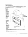
Installation Hardware
Mounting Space
Wall Construction
Hood Exhaust duct
Ventilation System Instruction
A. Horizontalventlla_onsystem
B.Verticalvenlllationsystem
C.Recirculadon
ventilationsystem
Checklist for Iustallation
Save this Guide with your Use & Care Manual
Introduction
Your Over-the-Range microwave oven comes complete with an installation instruction kit which contains
the following three pieces of information required to install it.
I. This installation instruction
booklet, complete with
diagrams on preparLng your
cabinets and microwave oven
for installation,
II.The Top Cabinet Template,
used to locate the power cord
clearance hole, cabinet
mounting holes and the vertical
exhaust location.
lIl. Instead ofThe Wall Mount
Template, Wall Mounting Plate,
used to locate the moun0ng
plate holes and to locate the
horizontal exhaust location.
Please read all of the instructiop.s
thoroughly before installing
your microwave oven.
NOTE:
1TIS RECOMMENDED
THAT TWO PEOPLE
INSTAl.I. THIS PRODUCT.
IMPORTANt.
I(_.P INSTRUCTIONS FOR
LOCAL 1_.1
.FETRICAL
INSPECTOR'S USF_.
Important Safety Information
Grounding Instructions
This appliance must be grounded. In the event of
an electrical short circuit, grounding reduces the
risk of the electric shock by providing an escape
wire for the electric current. This appliance is
equipped with a cord having a grounding wire
with a grounding plug. The plug must be plugged
into an outlet that is properly installed and
grounded.
A_-__
WARNING - Improper use of the grounding can
result in a riskof electric shock.
Consult a qualified electrician or serviceman if the
grounding
instructions
are not completely
understood, or if doubt exists as to whether the
appliance is properly grounded, and either:
1)flit is necessary to use an extension cord, use
onlya 3-wireextension
cordthathasa 3-blade
grounding plug, and a 3-slot receptacle that will
accept the plutg on the appliance. The marked
rating of the extension cord shall be equal to or
greater than the elect_cal rating of the appliance, or
Do not use an extension cord.
2)If the power supply cord is too short, have a
qualified electrician or serviceman install an
outlet
neartheappl_ance.
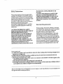
Safety Instructions
This product requires a three prong grounded
receptacle. The installer must perform a ground
continuity check on the power outlet box before
beginning the installation to insure that the outlet
box is properly grounded. If not properly
grounded, or if the outlet box does not meet the
electrical requirements noted, (under
ELECTRICALREQUIREMENTS),
a qualified
electrician should be employed to correct
any
deficiencies.
CAUTION: FOR PERSONAL SAFETY,
REMOVE HOUSE FUSE OR OPEN CIRCUIT
BREAKER BEFORE BEGINNING
INSTAI.I.ATION TO AVOID SEVERE OR
FATALSHOCK INJURY.CAUTION:FOR
PERSONAL SAFETY, THE MOUNTING
SURFACE MUST BE CAPABLE OF
SUPPORTING THE CABINET LOAD, IN
ADDITION TO THE ADDED WEIGHT OF
THIS 85 POUND PRODUCT, PLUS
ADDITIONAL OVEN LOADS OF UP TO 50
POUNDS OR A TOTAL WEIGHT OF 135
POUNDS.
CAUTION: FOR PERSONAL SAFETYTHIS
PRODUCT CANNOT BEINSTAI.1FD TO
CABINET ARRANGEMENT'S SUCH AS AN
ISLAND OR A PENINSULA. IT MUST BE
MOUNTED TO BOTH A TOP CABINET AND
A WAI.l..
Electrical
Requirements
Product rating is 120volts AC, 60Hertz, 14.6amps,
and 1.60kilowatts. This product must be connected
to a supply circuit of the proper voltage and
frequency Wire size must conform to the
requirements of the National Electric Code or the
prevailing local code for this kilowatt rating. The
power supply cord and plug should be brought to
a separate 20ampere branch cilxuit single grounded
receptacle. The outlet box should be located near
the cord entry point The outlet box and supply
circuit should be installed by a qualified electrician
and conform to the National FAectliCCode or the
Power supply cord
a) A short power-supply cord is provided to reduce the risks resulting from becoming entangled in or
Wipping over a longer cord.
b) Longer cord sets or extension cords are available and may be used if care is exercised in their use.
c) If a long cord or extemion cord is used:
1)The marked electrical rating of the cord set or extension cord should be at least as great as the
electrical rating of the appliance.
2) The e_tension _ord must be a grounding type 3-wire cord, and
3)The longer cord should be arranged so that it will not drape over the cotmte_ top or tabletop where it
can be pulled on by children or tripped over unintentionally
This over-the-range oven was designed for use over ranges no wider than 30inches. It may be installed over
both gas and electric cooking equipmenL
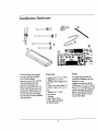
Installation
Hardware
®
The foUowing is a list ofparts
Parts List
Tools
you may need for installing
your Over-the-Range
microwave oven. Youwill find
them packaged inside the
microwave cooking cavity
Remove all parts from the oven
cavity and compare them with
the parts list and illustration to
be
are missing.
Usesure
thisthat
timenone
to become
familiar
1.Lag so'ews 1/4" x 2" (3EA)
2.Toggle Bolts 3" (3EA )
3.Spring Loaded ToggleNuts (
3EA)
4. Cabinet Mounting Bolts 1/4"
x3-1/8"(3EA),l/4"x2"(3
EA)
5. Washers 3/4" (3 EA)
6. Gromment
7. Damper
8. Foam Tape (2 EA)
9. Top Cabinet Template
10.Wall Template
The following tools may be
needed for installation of your
microwave oven.
Phillips screwdrivers, Electric
Drill Motor, 1/2" & 5/8" Wood
Bits & 3/16" Drill BiLSaw to cut
exhaust opening, (ifneeded) or
Jig Saw, Tm Snips (ifneeded),
Pencil,Tape Measure, Paper
Tape & Duct Tape.
with each piece.
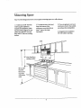
Mounting
Space
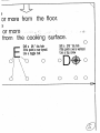
Your Over-the-Range microwave oven requires moun_ng space on a wall as shown.
1.A minimum of 30" between
wall hung side cabinets is
required for installation. Make
sure the bottom edge of the top
cabinet is at least 66" from the
floor and 30" from the cooking
surface.
30" cooking
more than
from
surface
66"or more
from the
floor to the
top of the
microwave
oven
2. For easier access to the hood
lamp, the bottom of the
microwave oven should be at
least 2" above the range
backsplash.
3. If you are going to vent your
microwave oven to the outside,
see exhaust duct preparation.
4. Designed to be installed in
30"wide cabinet opening.
_
Ni-l°
_
30"
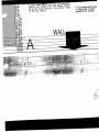
Wall Construction
Your Over-the-Rangemicrowaveoven shouldbe mounted againstand supported bya flat,verticalwall.
Wallconstructionshould be a minimum of2"x 4"wall studding and 3/8" ormore,thickdrywall or
plaster/lath. Theoven must be attachedto a minimum ofone 2"x 4" wallstud.
Forproper
installation the
wallmust be
capableof
supportingthe
cabinetload plus
a minimum of 135
pounds, (the85
pound weight of
the microwave
oven and load
weightallowance
of 50pounds.)
Tofind studs, use
one ofthe
following
methods"
Us11ally
16"or 24"
_
_°'
II ,@q
°'
"
:
:
3/8" Drywallor
Plaste_/ Lath
2"X4"
wood stud or
or metal stud
(25gaugeor thicker)
I
I
i
_q
I. Studfinder a
magneticdevice
which locates
nails.
1I.Using a
hammer,tap
lightlyacrossthe
mounting surface
to find a solid
sound. Thiswill
indicatea stud
installation. After
Logscrewsmust be installed
in these area
locatingthe
stud(s),the center
canbe found by:.Probingthe wallwith a smallnailto find the edgesofthe stud and then placinga mark
halfway between the edges.Thecenterofany adjacentstuds should be 16"or 24"fromthis mark.
NO'IE:Referencewalltemplate foraddildonalassistance.
Hood Exhaust Duct
Outside ventilation requires
HOOD EXHAUST DUCT.
Read the following carefully
EXHAUST CONNECT/ON:
The hood exhaust has been
designed to mate with a
standard 3-1/4" x 10"
rectangl llar duct.
If round duct is required, a
rectang_,l_r-to-mund
transition adapter must be
used. Do not use less than a 6"
diameter duct.
REAR EXHAUST: If rear or
horizontal exhaust is to be
used, care should be taken to
align exhaust with space
between studs, or wall should
be prepared at the time it is
comstructed by leaving enough
space between wall studs to
accommodate exhaust,
NOTE: Referencewall
template,
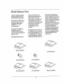
MAXIMUM DUCT LENGTH:
For satisfactoryair movemen_
the tot_ duct length of 3-1/4" x
10" mctang_fl_ror 6" diameter
round duct should not exceed
140feet of epuivalent duct run.
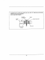
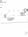
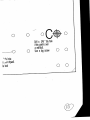
ELBOWS,TRANSITIONS,
WALL AND ROOF CAPS, etc.,
present additional resistance to
air flow and are equivalent to a
section of straight duct which is
longer than their actual
physical size. When calcula_hg
the total duct length add the
equivalent lengths of all
transitions and adaptors plus
the lengths of all su-aight duct
sections. The diagram below
shows the approximate feet of
equivalent length of some
typical ducts.
ROOF CAP(24Fr)
ADAerOR
(set)
90°ELBOW00Fr)
45°F_LBOW(5FT)
90° ELBOW(25FT)
45° ELBOW(5FD
6
WAI ,LCAP (40FI)
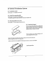
Ventilation system Instructions
Your Over-the-Range microwave oven is designed for adaptation to the following three types of
ventilation. Select the type of ventilation required for your instalhtion and proceed to the appropriate
section.
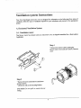
A. Horizontal
A-1. Ventilation
Ventilation System
motor
This blower motor has damper and your microwave oven is shipped assembled for a Recirculation
Application.
Step.1
* Remove the screws (1,2)for opening the
blower motor cover and save screws. Remove
cover.
* Remove the screw (2)for Blower attachment
and save screws.
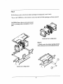
Step.2
* Liftblower unit out of mounting location.
CAUTION:
wiring.
Do not pull or stretch blower
C
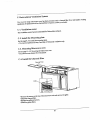
Step.3
Roll the blower unit so that the fan blade openings are facing back ( rear of unit ).
*If you want VERTICAL, roll the blower unit so that the fan blade openings are facing upward.
CAUTION: Wires to blower unit must be muted
avoid to pinching, before reinstallation of cover
plate.
Horizontal duct configuration
Step.4
* Carefully match the exhaust opening location
of the microwave oven and reinstall screws(I,2).
Vertical duct configuration
A-2. Install the Mounting Plate
Step. 1 Setup position
a. Draw a line down the middle of the studs(See the Wall Consa_ction, page 5)
b. Draw a vertical line on the wall at the center of the 30" wide space.
NOTE: Use the wall template for the rear wall.
Reference Wall Template prior to proceeding.
Installation of this product require TWO persons.
Step. 2 Drilling
Reference the Wall Template.
Step. 3 Install the damper
Fit the damper into the house duc_ Be sure that the damper hinge is on the top and the dotnper
free into the wall outlet.
Takethe28"foam
tapes
andremove
thepaperfrom
sticky
side.
Press
thesticky
sideonto
the front edge of the
damper. (Don't
stretch the foam
tape)
Plate
Step. 4 Tightening
the screws
ToAttach the mounting plate to the wall using the toggle bolt assemblies and/or lag screws:
a. Insert toggle bolts through mounting plate at required
locations and add the spring loaded toggles.
Reference wall template prior to proceeding
Be sure you leave space at least the thickness of the wall
between the mounting plate and the end of the toggle nuL (in
dosed position). If you do not leave this space, the toggle nut
will not open on the other side of the wall.
b. Posl_on moun_g plate on wall and insert toggle bolt
assemblies through the drywall holes or start the lag-screw(s)
throughthe
wall
stud(s).
c. Next, secure mounting plate to the wall by
tightening toggle bolt assemblies or lag screw(s).
d. Drill 3/16" diameter lag screw hole(s), into one
or more wall stud(s).
(Remember, you must have at least one lag screw
into a wall stud.)For stud location refer to W.ALI.
CONSTRUCTION see page 5.
e. Tighten the lag screw(S) into wall stud(S)
lO
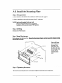
A-3. Mounting microwave oven
NOTE: ITIS VERYIMPORTANTTHATTHIS OVENBEINSTAlJ.FDBYTWO PEOPLE.
PREPARATIONOF TOP CABINET
Youneedto drillholesforthe top supportscrewsand a holelargeenough for the power cord to fitthrough.
• Read the instructionsonthe TOP CABINETTEMPLATE
• Tapeit underneath the top cabinet
• Drillthe holes,followingthe instructionson the template
NOTE:TOPCABINETTEMPLATEinstructionmust be completetoproceed.
Step. 1
Protectthe top of your range by placing a portion of the carton or some other heavy material over the
cookingsurfacebeforemountingyour oven.
Step. 2
Hang the unit on the two tabs at the bottomofthe mountingplate.
11
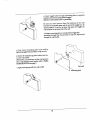
Step. 3
Thread power cord through the hole at the
bottomofthe top cabinet
Swing the unit upward to meet the top of the
mounting plateand hold secure.
l
Step. 4
Insert the 2 bolts through 2 flat washers into
holes on top cabinet floor. Tighten screws to
close the gap between top cabinet and the
miciDwave
oven.
NOTE: MICROWAVE OVEN MUST BE
SECURED WITH TWO MOUNTING
BOLTS.
Dresspower cord nearlyin top cabinet.
Installthe greasefilters.
12
* Using filler block for recessed bottom cabinet Insert a bolt. with a 3/4" washer into one of the holes
drilled previously in the top cabinet floor.
(D & E on Top Cabinet Template.)
Topcabinet
Cabinet
Washer
mountingscrew
_/
II Microwav_e
oventop
/
_
13
_ Cabinetbottom shelf
Filter block
B. Vertical Ventilation System
B-1. Ventilation
motor
Seethe page 7,A-I. Ventilationmotor,step 3.
B-2. Install the mounting
plate,
Seethe page 9,A-2.Installthe mountingplate.
• Youneed not performthe step2and step 4;Horizontalventilationonly.
B-3. Mounting
Microwave
oven
Seethe page 11,A-3.Mounl_g the Microwaveoven.
B-4. InstaU the Damper
attach the damper to the microwave through the
cabinet bottom. For front to back or side to side
For the verticalexhaust open the top cabinet and
adjustment,slidethe damper as needed.
'_
With
damper out,
twistplate.
the damper to fit
underthe
the flapsofthe
blower
Replacethe damper and make sumit willmoveeasilybythe forceofthe exhaustair.
Besum to square the comerson the hingeends.
A_ffer
the microwaveoven isinstalled,Pull the house duct downto conncetto the damper.
Installthe _p_asefilters.
14
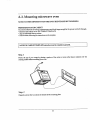
C. Recirculation Ventilation System
Your over the range microwave oven has been provided with a charcoal filter for a reO_htion
application. If replacement of the charcoal filter is required, contact your dealer.
C-1. Ventilation
motor
This ventilation motor has been assembled for Redro,!otion exhaust
C-2. Install the Mounting plate
See the page 9, A-2.Install the mounting plate.
• You need not perform the step 2 and step 4; Horizontal ventilation only.
C-3. Mounting
Microwave oven
See the page 11,A-3, MountSng the Microwave oven.
*Youneed not use damper for recirculation.
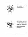
C-4. Install the Charcoal filter
CharcoalFilter
*Remove the screws on the top of the microwave unit and remove the grille.
*Install the charcoal filter.
*Replace the grille and screws.
*Install the grease filters.
15
venting
Checklist for Installation
1.Make sure oven has been instated according to these instructions and top cabinet template
2. Remove all packing material from the oven.
3. Plug in power cord.
4. Read Use and Care manual.
5. Keep installation instructions and template for the local electrical inspector s use.
16
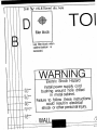
i
,n
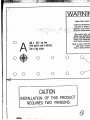
WARNI_Bec_cShockHazard
Locateanyelectricalcircui
lilac,c0uld be affectedI_
" "ns_lat_ o" " product
....
"
0
-.
A
Caremustbe"taken
whe
drilling
holes.
EIec'_wir,
maybe concededbeh.
ind
covering
andC_t_tv,_th
rt,.m
._,_G'_a,t_
_ _ __"_ _
p0JntJs
0vera
wallstud,
Use
a lagscrew
ifhS':":"
couldresult
in electrical
Fa/lure
to f_ow these
inst_
s_ ,._ _,_
o o o
0
0
0
O - -....©.:.
i IIII
0 ''_
"
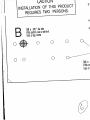
CAUTION
INSTALLATION
OF THISPRODUCT
REQUIRES
TWOPERSONS.
I',
Elecfi'i¢
ShockHazard
Locate
anyelectri_
drcuits
thatc(x_
be_fected
by
must
betaken
when
•drilling
holes,
Bed_cal,.wires
maybeconcea_
betted
w_1
covering
and_with
_em-
:aJfure
to fo/row
theseins_ctions
couldresult
inelectrical
shock
oroltlerpersonal
injury.
I'
,
'-
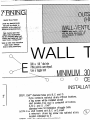
V,IIALL--
I O_
O_"_
E
ifthispoint
isover
drywall,
Use
atoggle
Drill
a
5,8"dbolt
ia.
hole
........ __MINIMU
30
--'o
o
o CEI
INSTALkAT
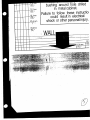
ifyou contacta wallstudatany oftheselocations,
a lag screw willbe installedatwall
STEP1.Drill*"diameter
stud location.
hIfno
olesatA,
stud B,C
is contacted
and D. at !ocations
A, B,C and D ; Dr,!l*"
diameterhoL-_torinstallationof togglebolts•
NOTI_:
t_no sTUdlocatedatA, B,C or D,insert
a minumumofone lag screw into wallstud at any
locationindicatedby E.
LL TEM!
/
rilla 5_"dia.h01e
thispoint
isover
dnjwall,
Isea toggle
b01t
|
INSTALLATION
INSTRUC
diameterholesatA, B,C and D.
,u contacta wallstud at anyoftheselocations,
lg screwwillbe installedatwall
' "ation.Ifno stud is contactedat locations
_,_ and D ;Dri!l*"
"neterhoJ_torinstallationoftogglebolts.
[ud locatedatA,B,C or D,insert
I
I
STEP3.Remove
the n
install
NOTE:TOP C,_
STEP4.Hang t
the
SE[
linumum
of one
ltion
indicated
bylag
E. screw into wailstud at any
I
STEP5.Thread
(_
at th_
"
66"or morefr,
Dnl
/!PLA--_-•.
'.I. DI::(31
I
IDEI'3
I I.I_/UI.
,LU
E ,,,t
_....
Eo
o
<F
:IUCTION
L_
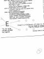
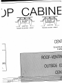
Removethewalltemplateandposition
the microwave
mountbracket
overthe drilledholes,
installbracket
withlag screwsand/ortogglebolts.
TOPCABINET
TEMPLATE
instruction
mustbe completeto proceed.
. Hangthe uniton thetabsatthe bottomof
the mountingplate.
SEETHEINSTALLATION
MANUAL,
PAGE11- 12
Threadpowercord
throughthe hole
atthebottomofthetop cabinet.,
swing
the unitupwardto mcctthewallandtop cabinet.
L
_ I,..I
.......
/-_--,-_"
Lgl
I'
I
_
.
t'°°_'°e
ormorefrom the floor.
.....
.
......
.-::-_:
:
-_ . -
fromthe cooking surface.
E
Drilla 5,8"dia.
hole
ifthispoint
isover
drywall,
Useatoggle
bolt
©
Drill
a 316'dia.
hole
ifthis
_intisover
awallstud,
Use
a lagscrew
\
C
'_O
0
0
O
0
I,,.,.,""--
U/-_UIILII_
INSTALLATION
OF THIS PRODUCT
REQUIRES
TWO PERSONS.
s,
N
B
o o
'ffthispoint
isover
awall
stud,
Drill
Use
aalag
3,16"
screw
dia.
hole
o
s
01--- Drill
a
ilthisp0i
Useatc
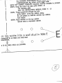
STEP1.
Drill*"alarn_t_,,,.,,oo
,.,,..,-, ifyoucontacta wallstud atanyoftheselocations,
a
lag screwwill
bestud
installed
atwall at!ou__t_ons
,- .
studlocation.
Ifno
is contacted
A,B,C andD ; Drill*"
diameter
bo_ _'orinstallation
oftogglebolts.
NOTI_:
-;fno stud locatedatA,B,C orD,insert
a minumumofonelag screwintowallstudatany
locationindicatedby E.
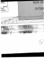
STEP2.
(skipforvertical
exhaust
installation)
Forhorizontal
exhaust
installation,
Cutopeningforexhaust
atshadedlocation
marked"OUTSIDE
EXHAUST(HORIZONTAL)".
mountbracket
to contacthorizontal
ducting.
Attachfoam tapeto backsideofmicrowave
o
_lnsert
I
I
I
a minimum of one (1) la
_
"t! a _."dia,h01e _
tr[hlS
p01nt
Isover
drywall.
Use
atoggle
bolt
i
o
I
"O
lu
O
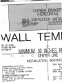
ThisovenMUS.Tbe conn.ect_
- this is a minimumrequlrem
O
(
Connectmarksto as
i
ii
]
the microwave
mount Drac_uLuv_J_,,_ ,.,,,,,,..
....... ,
installbracket
with lag screwsand/or
togglebolts.
NOTE:
TOPCABINET
TEMPLATE
instruction
mustbe completeto proceed.
STEP4.
Hangtheuniton thetabsatthebottomof
the mountingplate.
SEETHEINSTALLATION
MANUAL,
PAGE11- 12
STEP&Threadpowercord
throughthe hole
atthe bottomofthetop cabinet,swing
the unitupwardto mcctthewallandtop cabinet,
hold secure.
STEP6.
Placewasherson thetop cabinet
Secureboltsto microwave
cabinet.
I
(1)lag screwinto a wall stud in
"onnectea
to at leastonewallstud
o
eauirement.
s to as Imanystuds as possible.
o
holes,
)olts.
"omplete
to proceed.
1,- 12
#inet,
o o
E
:0
over
0
Use
a lagscrew 0
Drilla 58' clia,
h01e
ifthispoint
isover
d_all.
Use
a toggle
bolt
i
Drill
a 3,16
'dia.hole
O
i
ill
i
0
--------0
"_ia.
hole
s_erdrywall.
lebolt
0
0
0
C@
0
Drill
a 3,16"dia.hole
ifthis
poin!is
over
awallstud.
Use
a lagscrew 0
0
0
0
_J
o
Drill 5_,, (15.875mm) die. hole
D
fillerblock
--01
usefillerblockwhen
cabinetbottom is
recessed.
--
WARNING
_ic
Sh_ Hazard
6,mm
installpowersupplycord
0,/4..
bushingaroundholedrilled
127mm
In metalcabinet.
,9:,meFailureto followtheseinstructions
couldresultin electrical
2_.,mm shockorotherpersonal
injury.
31.8mm
%
i
i
10 i
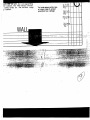
BINF
CA
I
I
•
top cabinet
cemp
.
¢entelr line
Smooth riot bottom
cobinet
Recessed bottom cobinet
- CEN1
Cutoutthisar_
ifventinc.
IET T MPL
"
,# _' _
_..-
fi,,,r
b,ock
s 'k/
_binet
I
NSTALURE
Filler block
S
CENTER
LINE
utoutthisai'ea
ofupper
cabinet
bottom
ifventing
through
theroof.
_
_I,--
C:)
O._j
_
i
ii ii
Drill 5_,, (15.875mm) dia. hole
ii i
ATE
CAUTION
E
fillerblock
i
_,TIONOF THIS PRODUCT
31RES TWO PERSONS.
i
i
Power
supply
cordh01e
NSTALLATION
INSTRUCTION
Cut
out 2 "dia.hole
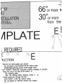
_TEP1. Cut the edges of the template at A,B and C, to
•fit in the recessed bottom of the top
cabinet so that template will ie flat
r
u_
r--
cutout 2 " (50.8ram)
diameter
hole
for powercord at F
Cut opening f_r ,,,_.{_-_texheust location.
against the top cabinet.
_TEP4. Remove the top cabinet template.
STEP5. Attach the filler blocks so that the holes
in each block line up with the corresponding
holes in the cabinet. The filler blocks should
be at the same levels as the bottom edge
of the top cobihet.
.
_
/t
_
_
_'
_
_
"Forrnetalcabim3t;putttle
tape
onedgeofholeto protect
fromdamage
6.4m_
_/,
12.7m
O_z"
1 "
31._
-
v4,,
bushingaroundhole drilled
__|_2._m
metalcabinet.
--I- '--,9._m_
-[-_,,
in
Failureto followtheseinstructiow
-----_,,
couldresultin electrical
__ __ .25._J_mr_shockorotherpersonal
injury.
1
,
1
i
,
I
11
31.8mm
II
:4
_
12.;
i
--'------
6.4mm
--
i
II
OVa,
drilled
jctions
trical
_1injury.
•
'
.4-mm
t/,,-
19.1mm.
31.8
.1
12.7mm 0_/4,,
01/2"
r/I/II/II//IHHH/H/H_'_f_HHHHH/"'''"''"""''''"''"
.._. :,-
_-':.,:.,,_3_"
.,.:._ -
-':
,..1
.................
i:"
,
;" ±-
in eoch block rne up with the corresponding
holes in the cobinet. The filler blocks should
be otthe same levels os the bottom edge
of the top cobihet.
"
Oz
m_
• . .-..
"'Formetalcabihet
putthe tape
on edgeofholeto pr(Xect
p_d
fromdamage
_..I
t.i.J
.r,.,'
/
_ith the corresponding
:he cabinet The filler blocks should
: some levels as the bottom edge
,p cobihet,
_ .-..-.
"'For_cabi_c,
puttt_etape
onedgeofholetoprotect
powercord
fromdamage
"
_-__w,
0
19.! rn_
0-_4"
25.4 m n
1"
31.8rr _n
11/4
,'
•
. .
I
_.
i
[.
1
"