1
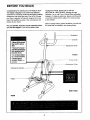
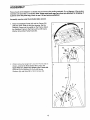
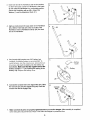
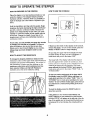
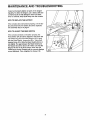
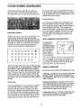
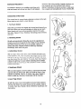
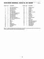
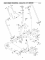
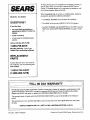
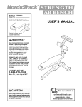
USER'S MANUAL
Model No. 831.283600
Model
Number
Decal
F-"
x
EZ
F_
_C.
i
S
E£"
EQUIPMENT
HELPLINE!
1-800-736-6879
SEARS, ROEBUCK AND CO.,
HOFFMAN ESTATES, IL 60179
www.weslo.com
new products, prizes,
fitness tips, and much more!
TABLE OF CONTENTS
IMPORTANT PRECAUTIONS
.............................................................
BEFORE YOU BEGIN ...................................................................
ASSEMBLY ...........................................................................
HOW TO OPERATE THE STEPPER ........................................................
MAINTENANCE AND TROUBLESHOOTING
..................................................
CONDITIONING GUIDELINES .............................................................
PART LIST ...........................................................................
EXPLODED DRAWING .................................................................
ORDERING REPLACEMENT PARTS ................................................
FULL 90 DAY WARRANTY
.......................................................
2
3
4
6
7
8
10
11
Back Cover
Back Cover
tions before using the stepper,
1. Read all instructions in th s manual before
.
do not wear loose c!othing tl_at could become
aescrmea in this manual.
SROeS lur IUUL pfUL_UUII.
2
:
::
BEFORE YOU BEGIN
Congratulations for selecting the new WESLO* ALTA
150 stepper. Stepping is one of the most effective
exercises for increasing cardiovascular fitness, building
endurance, and toning the body. The ALTA 150 stepper offers a selection of features designed to let you
enjoy this healthful exercise in the convenience and
privacy of your home.
For your benefit, read this manual carefully before
you use the stepper, If you have questions after
reading the manual, please call our toll-free
HELPLiNE at 1-800-736-6879, Monday through
Saturday, 7 a.m. until 7 p.m. Central Time (excluding
holidays). To help us assist you, please note the product model number before calling. The model number
is 831.283600.
Before reading further, please familiarize yourself with
the parts that are labeled in the drawing below.
Handlebar
Console
• Misuseoflhis pr_uct
may resultm senous
injury.
• Read user'smanual
and follow all warnings
and operatinginstructionspriorto use.
, Do netallow children
on or aroundmachine.
• Replacelabelif
damaged,illegible,or
removed.
Adjustment Knob
FRONT
Frame Knob
Resistance Collar
Resistance Cylinder
Pedal
RIGHT SIDE
REAR
ASSEMBLY
Place all parts of the stepper in a cleared area and remove the packing materials, Do not dispose of the packing
materials until assembly is completed. Note: Some small parts may have been pre-sttached for shipping. If
a part is not in the parts hag, check to see if it has been pre-attached.
Assembly requires only the included allen wrench.
1. Raise the Stabilizer Frame (23) and the Frame (29)
until they meet. Refer to the inset drawing. Set the
Stabilizer Frame into the saddle on the Frame. Attach
the Stabilizer Frame to the Frame with an M8 Curve
Washer (2} and the Frame Knob (36).
23
36
2. While holding the Upright (27) near the Frame (29) as
shown, connect the Reed Switch Wire (34) to the
Upper Wire (37). Attach the Upright to the Frame with
three M8 Curve Washers (2), three M8 Spring
Washers (9), and three M8 x 15ram Screws (3).
2
2
4
34_
2
29
3. Insert one end of the Handlebar (24) into the bracket
on the Frame (29). Center the Handlebar in the bracket and rotate the Handlebar to a comfortable position.
Secure the Handlebar with an M8 x 16mm Flat
11
Washer (1) and the Adjustment Knob (11).
"'29
Bracket
4. Apply a small amount of soapy water to the Handlebar
(24). Slide a Foam Grip (21) onto each side of the
Handlebar. Insert a Handlebar Endcap (20) into each
end of the Handlebar.
4
21
5. The Console (25) requires one =AA" battery (not
included). An alkaline battery is recommended. To
install batteries, turn the console over, remove the battery cover, and insert the battery into the battery clip
(not shown). Make sure that the negative end of the
battery (marked "--") is touching the spring in the
battery clip. Replace the battery cover.
6. Connect the console wire to the Upper Wire (37). Slide
the Console (25) onto the Upright Cap (26). Insert the
excess wire into the Upright Cap.
7.
Battery
over
®
sI
_
6
Console
Battery
25
Make sure that all parts are properly tightened before you use the stepper, After assembly is completed,
some extra parts may be left over. Place a mat under the stepper to protect the floor.
5
HOW TO OPERATE THE STEPPER
HOW TO USE THE CONSOLE
HOW TO EXERCISE ON THE STEPPER
Place the stepper on a level surface and place a mat
under the stepper. (The stepper features precision
hydraulic cylinders. However, there is a possibility of
slight oil leakage due to the nature of hydraulic cylinders.)
CNT
STRIDES
/MIN
Hold the handlebars and step onto the pedals. Begin
stepping, alternately depressing the right and left pedals with a smooth, continuous motion. Because the
pedals move independently of each other, you must
maintain a continuous motion or both pedals will sink
to the floor. Change the height of your step or the
stepping pace until you can comfortably maintain a
continuous motion.
SCAN
As you step, you can exemise your upper leg muscles
by keeping your feet flat on the pedals. To focus on
your calf muscles, rise on your toes as you step.
Stand erect or lean forward slightly as you exercise.
Always keep your back straight in order to avoid
injury.
i lu/
:J.luj
"H_I !7'1
TIME
CAL
If there is a thin sheet of clear plastic on the console,
remove the plastic. To turn on the console, press the
MODE or RESET button or begin stepping.
As you step, the upper half of the display will show
the total number of steps you have completed. A
mode arrow will point to the letters "CNT."
HOW TO ADJUST THE RESISTANCE
To change the stepping resistance, simply turn the
resistance collars on the upper ends of the Resistance
Cylinders (28) (see the inset drawing). The arrows on
the Resistance Cylinders and the markings on the
resistance collars show which resistance level has
been selected. Make sure that both Resistance
Cylinders are at the same resistance setting.
The lower half of the display will show the elapsed
time, the approximate number of calories you have
burned, and your stepping speed, changing from one
mode to the next every few seconds. One mode
arrow will point to the word "SCAN," and a second
mode arrow will point to the letters 'q'IME," =CAL," or
"STRIDES/MIN."
To view one mode continuously in the lower half of
the display, press the MODE button until there is a
mode arrow pointing to the letters "TIME," "CAL," or
"STPS/MIN" but no mode arrow pointing to the word
=SCAN." To view all three modes again, press the button until there is a mode arrow pointing to the word
"SCAN."
I
I
//
To reset the display, press the RESET button for
about two seconds.
If the pedals are not moved and the MODE and
RESET buttons are not pressed for a few seconds,
the word "STOP" will appear in the left side of the display. If the pedals are not moved and the buttons are
not pressed for a few minutes, the console will turn
off.
6
MAINTENANCE
AND TROUBLESHOOTING
Inspect and properly tighten all parts of the stepper
regularly. To clean the stepper, use a damp cloth and
a small amount of mild detergent. Never use abrasives or solvents; keep liquid away from the console.
HOW TO REPLACE THE BAI-I'ERY
If the console does not function properly, or if the display becomes faint, the battery should be replaced.
See assembly step 5 on page 5.
HOW TO ADJUST THE REED SWITCH
If the console still does not function properly, the
Reed Switch (34) should be adjusted. Hold down the
Left Pedal Leg (40) so that the Magnet (35) is level
with the Reed Switch. Loosen the M5 x 10mm Selftapping Screw (13). Slide the Reed Switch (34) in or
out slightly. The gap between the Reed Switch and
the Magnet should be about 1/8". Make sure that the
Magnet will not hit the Reed Switch when the Left
Pedal Leg is moved. Repeat until the console displays
correct feedback. Then, retighten the Screw (13).
7
CONDITIONING
GUIDELINES
The following guidelines will help you to plan your
exercise program. Remember that proper nutrition
and adequate rest are essential for successful results.
bet in your training zone as you exercise, For maximum fat burning, adjust the intensity of your exemise
until your heart rate is near the middle number in your
training zone as you exercise.
Aerobic Exercise
If your goal is to strengthen your cardiovascular system, your exercise must be "aerobic." Aerobic exercise is activity that requires large amounts of oxygen
for prolonged periods of time. This increases the
demand on the heart to pump blood to the muscles,
and on the lungs to oxygenate the blood. For aerobic
exercise, adjust the intensity of your exercise until
your heart rate is near the highest number in your
training zone.
EXERCISE INTENSITY
Whether your goal is to burn fat or to strengthen your
cardiovascular system, the key to achieving the
desired results is to exercise with the proper intensity.
The proper intensity level can be found by using your
heart rate as a guide. The chart below shows recommended heart rates for fat buming, maximum fat
buming, and cardiovascular (aerobic) exercise.
165 155 145 140 130 125
115
145
118 110
103
125 120 115 110 105 95
90
20
138 130 125
30
40
50
60
70
HOW TO MEASURE YOUR HEART RATE
To measure your
heart rate, first
exercise for at least
four minutes. Then,
stop exercising and
place two fingers
on your wrist as
shown. Take a sixsecond heartbeat
count, and multiply the result by 10 to find your heart
rate. For example, it your six-second heartbeat count
is 14, your heart rate is 140 beats per minute. (A sixsecond count is used because your heart rate wi,
drop rapidly when you stop exercising.)
_1_
V
80
To find the proper heart rate for you, first find your age
at the bottom line of the chart (ages are rounded off to
the nearest ten years). Next, find the three numbers
above your age. The three numbers are your "training
zone." The lowest number is the recommended heart
rate for fat burning; the middle number is the recommended heart rate for maximum fat burning; the highest number is the recommended heart rate for aerobic
exercise.
WORKOUT GUIDELINES
Each workout should include the following three pads:
A warm-up, consisting of 5 to 10 minutes of stretching
and light exercise. A proper warm-up increases your
body temperature, heart rate, and circulation in preparation for exercise.
Training zone exercise, consisting of 20 to 30 minutes of exercising with your heart rate in your training
zone. Note: During the first few weeks of your exercise program, do not keep your heart rate in your
training zone for longer than 20 minutes.
Fat Burning
To burn fat effectively, you must exercise at a relatively low intensity level for a sustained period of time.
During the first few minutes of exercise, your body
uses easily accessible carbohydrate calories for energy. Only after the first few minutes of exercise does
your body begin to use stored fat calories for energy.
If your goal is to burn fat, adjust the intensity of your
exercise until your heart rate is near the lowest hum-
A cool-down, with 5 to 10 minutes of stretching, This
will increase the flexibility of your muscles and will
help to prevent post-exercise problems.
8
workouts. After a few months of regular exercise, you
may complete up to five workouts each week, if
desired. Remember, the key to success is make exercise a regular and enjoyable part of your everyday life.
EXERCISE FREQUENCY
To maintain or improve your condition, plan three workouts each week, with at least one day of rest between
SUGGESTED STRETCHES
The correct form for several basic stretches is shown at the right.
Move slowly as you stretch--never bounce.
1. Toe Touch Stretch
Stand with your knees bent slightly and slowly bend forward from
your hips. Allow your back and shoulders to relax as you reach
down toward your toes as far as possible. Hold for 15 counts,
then relax. Repeat 3 times. Stretches: Hamstrings, back of knees
and back.
2. Hamstring Stretch
Sit with one leg extended. Bring the sole of the opposite foot
toward you and rest it against the inner thigh of your extended
leg. Reach toward your toes as far as possible. Hold for 15
counts, then relax. Repeat 3 times for each leg. Stretches:
Hamstrings, lower back and groin.
3. Calf/Achilles Stretch
With one leg in front of the other, reach forward and place your
hands against a wall. Keep your back leg straight and your back
loot flat on the floor Bend your front leg, lean forward and move
your hips toward the wall. Hold for 15 counts, then relax. Repeat
3 times for each leg. To cause further stretching of the achilles
tendons, bend your back leg as well. Stretches: Calves, achilles
tendons and ankles.
4. Quadriceps Stretch
With one hand against a wall for balance,
one foot with your other hand. Bring your
buttocks as possible. Hold for 15 counts,
times for each leg. Stretches: Quadriceps
reach back and grasp
heel as close to your
then relax. Repeat 3
and hip muscles.
5. Inner Thigh Stretch
Sit with the soles of your feet together and your knees outward.
Pull your feet toward your groin area as far as possible. Hold for
15 counts, then relax. Repeat 3 times. Stretches: Quadriceps and
hip muscles.
9
#
EXPLODED DRAWING--Model
Key No, Qty.
No. 831.283600
Key No. Qty.
Description
Rogo2A
Description
1
2
3
4
5
6
7
8
9
10
5
6
3
6
4
2
8
2
7
4
M8 x 16ram Flat Washer
M8 Curve Washer
M8 x 15mm Screw
M8 Nylon Nut
M8 x 40mm Bolt
M8 x 68mm Bolt
1/4° x 5/8" Self-tapping Screw
M8 x 38mm Flat Washer
M8 Spring Washer
M8 x 25mm Bolt
23
24
25
26
27
28
29
30
31
32
1
1
1
1
1
2
1
1
1
1
Stabilizer Frame
Handlebar
Console
Upright Cap
Upright
Resistance Cylinder
Frame
Right Base
Left Base
Pivot Frame
11
12
13
14
15
16
17
18
19
20
21
22
1
2
1
10
2
2
4
2
2
2
2
2
Adjustment Knob
M8 x 12mm Flat Washer
M5 x 10ram Self-tapping Screw
Pivot Bushing
Cap
Bump-on
Foot
Pedal
Base Endcap
Handlebar Endcap
Foam Grip
Spacer
33
34
35
36
37
38
39
40
41
#
#
1
1
1
1
1
2
1
1
1
1
1
Pivot Axle
Reed Switch/Wire
Magnet
Frame Knob
Upper Wire
M8 x 25mm Patch Screw
Reed Switch Spacer
Left Pedal Leg
Right Pedal Leg
User's Manual
Allen Wrench
Note: "#" indicates a non-illustrated part. Specifications are subject to change without notice. See the back cover
of this manual for information about ordering replacement parts.
10
EXPLODED DRAWING--Model
No. 831.283600
R0OO2A
21
22
14
18
22
14
14
32
31
17
14
11
SEARS
All replacement parts are available for immediate purchase or
special order when you visit your nearest SEARS Service
Center. To request service or to order parts by telephone, call
the toll-free numbers listed at the left.
Model No. 831.283600
When requesting help or service, or ordering parts, please be
prepared to provide the following information:
• The MODEL NUMBER of the product (831.283600)
QUESTIONS?
• The NAME of the product (WESLO ®ALTA 150 stepper)
If you find that:
• you need help assembling or
operating the WESLO ®ALTA 150
stepper
• The KEY NUMBER and DESCRIPTION of the PART (see the
PART LIST and the EXPLODED DRAWING on pages !0 and
11)
• a part is missing
• or you need to schedule repair
service
call our toll-free HELPLINE
1-800-736-6879
Monday-Saturday, 7 am-7 pm
Central Time (excluding holidays)
REPLACEMENT
PARTS
If parts become worn and need to
be replaced, call the following tollfree number
1-800-FON-PART
(1-800-366-7278)
[
FULL 90 DAY WARRANTY
]
For 90 days from the date of purchase, if failure occurs due to defect in material or workmanship in this
SEARS STEPPER EXERCISER, contact the nearest SEARS Service Center throughout the United
States and SEARS will repair or replace the STEPPER EXERCISER, free of charge.
This warranty does not apply when the STEPPER EXERCISER is used commercially or for rental purposes.
This warranty gives you specific legal rights, and you may also have other rights which vary from state
to state.
SEARS, ROEBUCK AND CO., DEPT. 817WA, HOFFMAN
Part No. 190614 R0902A
ESTATES, IL 60179
Printed in China © 2002 Sears, Roebuck and Co.