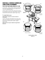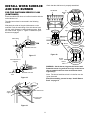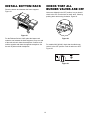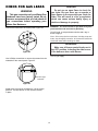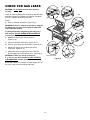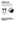
1
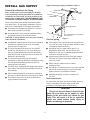
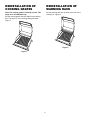
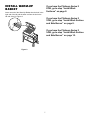
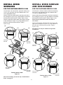
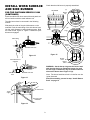
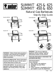
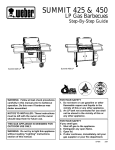
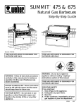
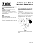
PLATINUM SERIES II
™
Natural Gas Barbecues
Step-By-Step Guide
Platinum Series II
2200 NG
Platinum Series II
3400 NG
Platinum Series II
3200 NG
CANADIAN GAS ASSOCIATION
®
R
WARNING: Do not operate this barbecue
without reading the entire operating guide.
THIS GAS APPLIANCE IS DESIGNED FOR
OUTDOOR USE ONLY.
WARNING: Follow all leak check
procedures carefully in this manual prior to
barbecue operation. Do this even if
barbecue was dealer assembled.
APPROVED
NOTICE TO INSTALLER: These instructions
must be left with the owner and the owner
should keep them for future use.
FOR YOUR SAFETY
If you smell gas:
1. Shut off gas to the appliance.
2. Extinguish any open flame.
3. Open lid.
4. If odor continues, immediately call your
gas supplier or your fire department.
97461
12/96
INSTALL GAS SUPPLY
Typical natural gas supply installation. Figure 1.
Gas supply
General Specifications for Piping
Inside wall
Note - Contact your local municipality for building
codes regulating outdoor gas barbecue installations.
In absence of Local Codes, you must conform to the
latest edition of ANSI Z223.1. WE RECOMMEND THAT
THIS INSTALLATION BE DONE BY A PROFESSIONAL.
Outside wall
Shut off
Some of the following are general requirements taken
from ANSI Z223.1, for gas supply installations. Refer to
ANSI Z223.1 latest edition for complete specifications.
■
This barbecue is designed to operate at 7 inches of
water column pressure (.2526 psi).
■
A manual shut-off valve must be installed outdoors,
immediately ahead of the quick disconnect.
Quick Disconnect
Locking shut off
The quick disconnect is installed
above ground
CAUTION: If young children are in the area, a locking
valve should be considered.
Gas line piping
■
An additional manual shut-off valve indoors should be
installed in the branch fuel line in an accessible
location near the supply line.
■
If the length of line required does not exceed 50 feet,
use a 5/8" O.D. tube. One size larger should be used
for lengths greater than 50 feet.
■
The quick disconnect connects to a 3/8 inch NPT
thread from the gas source. The quick disconnect
fitting is a hand-operated device that automatically
shuts OFF the flow of gas from the source when the
barbecue is disconnected.
■
Gas piping may be copper tubing, type K or L;
polyethylene plastic tube, with a minimum wall
thickness of .062 inch; or standard weight (schedule
40) steel or wrought iron pipe.
■
■
The quick disconnect fitting can be installed
horizontally, or pointing downward. Installing the fitting
with the open end pointing upward can result in
collecting water and debris.
Copper tubing must be tin-lined if the gas contains
more than 0.3 grams of hydrogen sulfide per 100
cubic feet of gas.
■
Plastic tubing is suitable only for outdoor,
underground use.
■
Gas piping in contact with earth, or any other material
which may corrode the piping, must be protected
against corrosion in an approved manner.
Underground piping must have a minimum of
18” cover.
■
The dust covers (supplied plastic plugs) help keep the
open ends of the quick disconnect fitting clean while
disconnected.
■
Pipe compound should be used which is resistant to
the action of natural gas when connections are made.
■
■
The outdoor connector must be firmly attached to
rigid, permanent construction.
Test connections
Figure 1
All connections and joints must be thoroughly tested for
leaks in accordance with local codes and all listed
procedures in the latest edition of ANSI Z223.1.
DANGER
Do not use an open flame to check for gas
leaks. Be sure there are no sparks or open
flames in the area while you check for gas
leaks. This will result in a fire or explosion
which can cause serious bodily injury or
death, and damage to property.
2
TOOLS NEEDED
REMOVE BOTTOM TRAY
FROM GRILL
Phillips screwdriver
Remove bottom rack from top of packaging. Remove all
tape from packaging. Remove outer box. Pull out bottom
tray from cooking box. Remove packaging material from
bottom tray, catch pan holder, catch pan, and drip pan.
For the Platinum Series II 3400, remove the white plastic
from the stainless steel.
7/16 inch or adjustable wrench
SUPPLIES NEEDED
You will need a soap and water solution to check for gas
leaks. (See section “Check for Gas Leaks.”)
Refer to exploded view in the Operating Guide if
replacement parts are needed.
Bottom tray
While we give much attention to our products, unfortunately an occasional error may occur. If a part is
missing, do not go back to the store. Call the Weber
Customer Service Center toll free 1-800-446-1071 to
receive immediate assistance. Have your owner’s
manual and serial number of the barbecue available
for reference.
Figure 2
Bottom wire rack
Bottom tray
Catch pan holder
Catch pan
Drip pan
Four 1/4-20 inch bolts
Four nylon washers
3
REMOVE GRILL FROM
LOWER PACKAGING
REMOVE PACKAGED
PARTS FROM LOWER
CARTON
Make sure natural gas hose is free from lower packaging
before lifting.
Left work surface
WARNING: Lifting the barbecue from the lower
packaging requires at least two people.
With two people lift straight up and over lower packaging
and cardboard support.
Note: For the Platinum Series II 3400, make sure the front
doors are securely closed before lifting.
Right work surface
(Platinum Series II 2200 NG only)
Side burner
(Platinum Series II 3200 NG and 3400 NG only)
Note: For the Platinum Series II 3200 and 3400, remove
the white plastic on the stainless steel of the side burner.
Figure 3
Hose
4
INSTALLATION OF CATCH
PAN INTO BOTTOM TRAY
REINSTALLATION OF
STAINLESS STEEL
FLAVORIZER BARS
Hook the ends of the catch pan holder into the hole in the
bottom tray. Figure 4. The front of the catch pan holder
must be on the same side as the finger grip of the
bottom tray.
Note: Remove any tape or packing material. Parts are
shipped in place. Use these steps to check that they are
in position. The Flavorizer bars are already in place.
This step is only for reinstallation.
Set the long stainless steel Flavorizer bars side to side in
the lower position of the cooking box. Insert the front two
Flavorizer bars through the Steam-N-Chips Smoker flue.
Figure 5.
Front of
catch pan
holder
Finger grip
Figure 4
Slide the bottom tray onto the mounting rails under the
cooking box with finger grip toward you.
CAUTION: Do not line bottom tray with aluminum foil.
It can cause grease fires by trapping the grease and
not allowing grease to flow into the catch pan.
Put the foil drip pan into the catch pan.
Flue
Slide the catch pan into the catch pan holder with its
finger grip towards you.
Figure 5
Set the short stainless steel Flavorizer bars front to back
in the upper position. Figure 6. Place Steam-N-Chips
Smoker so it opens towards Flavorizer bars.
Figure 6
5
REINSTALLATION OF
COOKING GRATES
REINSTALLATION OF
WARMING RACK
Note: The cooking grates are already in place. This
stepp is for reinstallation only.
Set the warming rack into the slots at the rear of the
cooking box. Figure 8.
Set the cooking grates onto the ledges in the cooking
box. The open "U" of the cooking grate goes down.
Figure 7.
Figure 8
Figure 7
6
INSTALL WARM-UP
BASKET
If you have the Platinum Series II
2200, go to step “Install Work
Surfaces” on page 8.
Insert one end of the Warm-Up Basket into the hole in the
right end of the lid and the other end into the slot in the
left end of the lid. Figure 9.
If you have the Platinum Series II
3200, go to step “Install Work Surface
and Side Burner” on page 8.
If you have the Platinum Series II
3400, go to step “Install Work Surface
and Side Burner” on page 10.
Figure 9
7
INSTALL WORK
SURFACES
INSTALL WORK SURFACE
AND SIDE BURNER
FOR THE PLATINUM SERIES II 2200
FOR THE PLATINUM SERIES II 3200
You will need...left work surface, right work surface, four
1/4-20 x 1/2 inch bolts, four nylon washers and a 7/16
inch or adjustable wrench.
You will need... left work surface, side burner assembly,
four 1/4-20 x 1/2 inch bolts, four nylon washers and a
7/16 inch or adjustable wrench.
Insert the left work surface tabs in the slots to the left of
the cooking box. Figure 10 (a). Slip washers on the bolts
and insert the bolts as shown. Tighten. Figure 10 (b).
Insert the left work surface tabs in the slots to the left of
the cooking box. Figure 11 (a). Slip washers on the bolts
and insert the bolts as shown. Tighten. Figure 11 (b).
Insert the right work surface tabs in the slots to the right
of the cooking box. Figure 10 (c). Slip washers on the
bolts and insert the bolts as shown. Tighten.
Figure 10 (d).
Note: Remove protective covers from tabs of
side burner.
Insert the side burner assembly tabs in the slots to the
right of the cooking box. Figure 11 (c). Slip washers on
the bolts and insert the bolts as shown. Tighten.
Figure 11 (d).
(a)
Tabs
(c)
Side burner can only be installed on right side
of barbecue.
(a)
View from
left side
Tabs
(c)
View from
right side
View from
left side
View from
right side
(b)
(d)
(b)
(d)
View from left
underside
View from right
underside
View from left
underside
Platinum Series II 2200
Figure 10
Platinum Series II 3200
Figure 11
After this assembly, proceed to step “Install Bottom
Rack” on page 12.
8
View from right
underside
INSTALL WORK SURFACE
AND SIDE BURNER
Check that the side burner is properly assembled.
Windshield
(c)
Burner
cap
FOR THE PLATINUM SERIES II 3200
(CONTINUED)
Route the side burner hose around the tank panel so it
will not interfere with the scale indicator rod.
The side burner hose is connected in the following
manner:
Slide back the collar of the quick disconnect on the
manifold. Push the male fitting of the side burner hose
into the quick disconnect, and maintain pressure. Slide
the collar closed. Figure 12. Figure 13 shows the quick
disconnect engaged.
(b)
Grate
Burner
ring
Lugs
Male fitting
Slots
Burner
head
(a)
Manifold side view
Figure 15
Figure 12
Burner
base
Burner
orifice
Quick disconnect
engaged
Side burner
hose
Igniter
electrode
WARNING: Set the burner ring onto the burner head
with the slots facing up. Rotate the burner ring until
the four lugs on the burner ring are seated in the four
slots on the burner head. Figure 15 (b).
Manifold side view
Note: The burner head has a hole in it that fits over the
igniter electrode.
Figure 13
After this assembly, proceed to step “Install Bottom
Rack” on page 12.
To side burner
To NG
supply
View from right
underside
Figure 14
9
INSTALL WORK SURFACE
AND SIDE BURNER
(a)
Tabs
(c)
FOR THE PLATINUM SERIES II 3400
You will need... left work surface, side burner assembly,
four 1/4-20 x 1/2 inch bolts, four nylon washers and a
7/16 inch or adjustable wrench.
Insert the left work surface tabs in the slots to the left of
the cooking box. Figure 16 (a). Slip washers on the bolts
and insert the bolts as shown. Tighten. Figure 16 (b).
View from
left side
View from
right side
To install side burner
Note: Remove protective covers from tabs of
side burner.
Insert the side burner assembly tabs in the slots to the
right of the cooking box. Figure 16 (c). Slip washers on
the bolts and insert the bolts as shown. Tighten.
Figure 16 (d).
(b)
Side burner can only be installed on right side of
barbecue.
(d)
Left panel
View from left side
Platinum Series II 3200
Figure 16
10
View from right
underside
INSTALL WORK SURFACE
AND SIDE BURNER
Check that the side burner is properly assembled.
Windshield
FOR THE PLATINUM SERIES II 3400
(CONTINUED)
(c)
Burner
cap
Route the side burner hose so it will not interfere with the
scale indicator rod.
The side burner hose is connected in the following
manner:
Slide back the collar of the quick disconnect on the
manifold. Push the male fitting of the side burner hose
into the quick disconnect, and maintain pressure. Slide
the collar closed. Figure 17. Figure 18 shows the quick
disconnect engaged.
(b)
Grate
Burner
ring
Lugs
Male fitting
Slots
Burner
head
(a)
Manifold side view
Figure 20
Figure 17
Burner
base
Burner
orifice
Quick disconnect
engaged
Side burner
hose
Igniter
electrode
WARNING: Set the burner ring onto the burner head.
Rotate the burner ring until the four lugs on the burner
ring are seated in the four slots on the burner head.
Figure 20 (b).
Manifold side view
Note: The burner head has a hole in it that fits over the
igniter electrode.
Figure 18
After this assembly, proceed to step “Install Bottom
Rack” on page 12.
To side burner
To NG
supply
View from right
underside
Figure 19
11
INSTALL BOTTOM RACK
CHECK THAT ALL
BURNER VALVES ARE OFF
Place the bottom rack between the frame supports.
Figure 21.
Valves are shipped in the OFF position, but you should
check to be sure. Put the knob on each valve. Check by
pushing down and turning clockwise. Figure 22.
Figure 21
Figure 22
For the Platinum Series II 3400, place the bottom rack
under the cart between the frame supports. Lift up one end
of the rack so that it clears the crosspiece. Continue to lift
until the opposite end clears the opposite crosspiece. Set
the rack in place on both crosspieces.
For models 3200 & 3400, check that the side burner
valve is in the OFF position. Push in and turn to OFF.
Figure 23.
Figure 23
12
CHECK FOR GAS LEAKS
DANGER
Do not use an open flame to check for
gas leaks. Be sure there are no sparks or
open flames in the area while you check for
leaks. This will result in a fire or explosion
which can cause serious bodily injury or
death and damage to property.
WARNING
This gas connections of your Weber Gas
Barbecue have been factory tested. We do
however recommend that you leak check all
gas connections before operating your
Weber Gas Barbecue.
WARNING: You should check for gas leaks every time
you disconnect and reconnect a gas fitting.
Remove the knobs from the control panel. Figure 24.
You will need: a soap and water solution and a rag or
brush to apply it.
Note - Since some leak test solutions, including soap and
water, may be slightly corrosive, all connections should be
rinsed with water after checking for leaks.
WARNING
Make sure all burner control knobs are in
the OFF position, including the side burner,
if the barbecue has a side burner.
Figure 24
Turn on gas supply.
Use a Phillips screwdriver to remove the screws from the
underside of the control panel. Figure 25.
View from right
underside
Figure 25
Stand at the right end of the barbecue. Lift the control
panel off. The side burner or work surface remains
in place.
13
CHECK FOR GAS LEAKS
(b)
WARNING: Do not ignite burners while checking
for leaks.
Check for leaks by wetting the connections with the soap
and water solution and watching for bubbles. If bubbles
form or if a bubble grows there is a leak.
(c)
(a)
Check:
a) Hose to manifold connection. Figure 26 (a).
WARNING: If there is a leak at connection a, retighten
the fitting with a wrench and recheck for leaks with
soap and water solution.
(d)
If a leak persists after retightening the fitting, turn
OFF the gas. DO NOT OPERATE THE BARBECUE.
Contact your dealer.
b) Manifold to side burner hose connection.
Figure 26 (b).
(f)
c) Valves to manifold connections. Figure 26 (c).
d) Hose to quick disconnect connection. Figure 26 (d).
(e)
e) Side burner supply line to side burner orifice
connection. Figure 26 (e).
f)
Side burner hose to side burner valve, and side
burner supply line to side burner valve. Figure 26 (f).
WARNING: If there is a leak at connections
b, c, d, e or f, turn OFF the gas. DO NOT OPERATE
THE BARBECUE. Contact your dealer.
View from below
Figure 26
When leak checks are complete, turn gas supply OFF at
the source and rinse connections with water.
14
REINSTALL THE
CONTROL PANEL
Set the control panel in place over both frame braces.
(Hold the Crossover Ignition button up while setting the
control panel in place.) Slip washers on Phillips screws,
insert into holes as shown, and tighten. Figure 27 (a).
Push on the burner control knobs. Figure 27 (b).
(b)
(a)
Underside view
of right work
surface or side
burner
Figure 27
REFER TO OPERATING
GUIDE BEFORE LIGHTING
BARBECUE